Week 6- Challenge
2D SURFACE MESHING AND MIDDLE-SURFACE EXTRACTION FOR HOOD MODEL USING HYPERWORKS AS PER THE GIVEN QUALITY CRITERIA.
Objective: To mesh the 2D surface after extracting each and every component of the hood separately using Hypermesh as per the Quality Criteria given.
Importing CAD model and geometrical clean up
When the CAD model is clean then no need go through the geometry clean-up but we need to check the geometry properly before extract the mid surface. Depending on complexity of the model, we can make the model symmetrical so that it is easy to work on the model.
File (type) > Import > CAD model.
While Import the CAD model file (step or IGES etc.) the model may have geometrical errors like unconnected, missing and duplicate surfaces also overlap surfaces due to small geometry areas in the model. Cleanup operations include the equivalence of "red" free edges, fixing of small surfaces (relative to the element size), and detection of features such as beads. It also performs specified surface editing or de-featuring operations like the removal of pinholes (less than specified size), removal of edge fillets, and the addition of a layer of washer elements around holes.
We have Hood CAD model here, it is divided into five separate components .All the five components go through the same sequence of steps here but to reduce the size of the report we are presenting only few images here in the document.
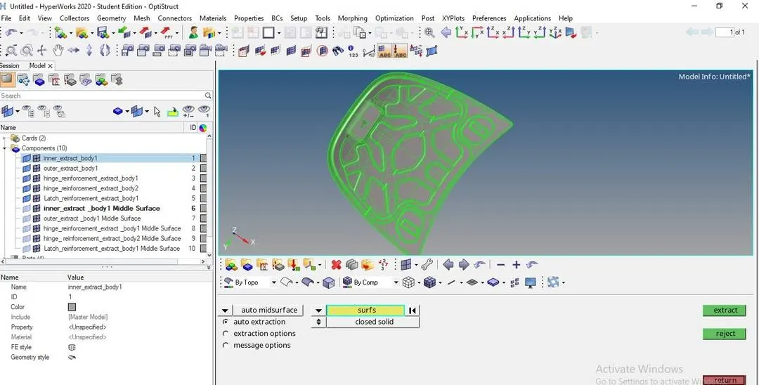
After importing the CAD model clean the geometry whether any errors present in the model.
CAD model is clean now we can extract the Mid-surface of the hood.
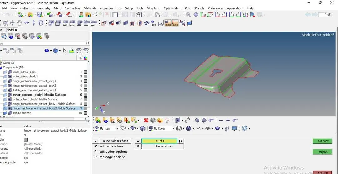
Auto Mid-surface: Automatically extracts mid-surfaces from surfaces that enclose a volume or a solid geometry can sometimes work if there are missing surfaces. The greater number of missing surfaces, the less reliable the result
Auto –middle surface extraction: Use the Auto Mid-surface subpanel to extract the mid-surface of a more complicated group of surfaces that represent a solid part in one step.
The Mid-surface panel can be used to extract the mid-surface of sheet metal stampings, molded plastic parts with ribs, and other parts that have thickness clearly smaller than width and length.
Geometry > mid-surface > Auto Mid-surface > change the extraction options like
Identify the places where a piece of plane or a piece of a sweep surface can be used as a middle surface. A middle surface is constructed at the remaining places in the model, this is offset + plane + sweep method. Using this method middle surface got distorted.
All other three methods like, offset + plane +sweep, offset + plane, offset in the extraction option created are tried but did not give proper mid surface in some areas. In skin offset gave proper middle surface.
The fillet or shared edge fall less, the offset size of the fillet is small due that both surface got intersected in the below image after creating the mid–surface.
Using Surface edit we can rectify the error, geometry > surface edit > trim with surface/plane > select with surface we can select both surfaces one after another then click on trim.
After deleting the solids we can extract the mid-surface using auto mid-surface. This is inner extract body of the hood. Geometry > mid-surface > auto-mid-surface, here we can select the extracting option for the component based on the surface fillet.
We have extracted Mid-surface separately for each component.
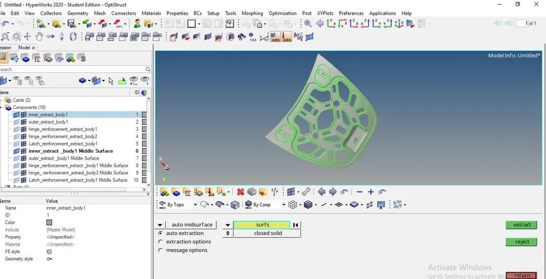
It’s easy to extract any model extracting the mid-surface using auto middle surface but we need to check up middle surface any fallen edges or any other geometrical errors present in the model after this step. Now we need to go through the auto cleanup
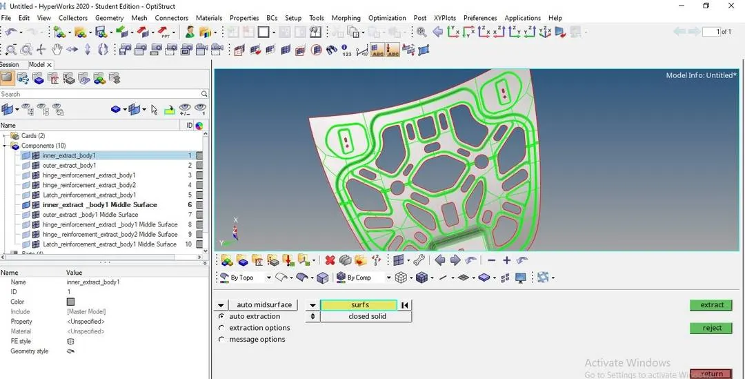
Outer extract body of the Hood
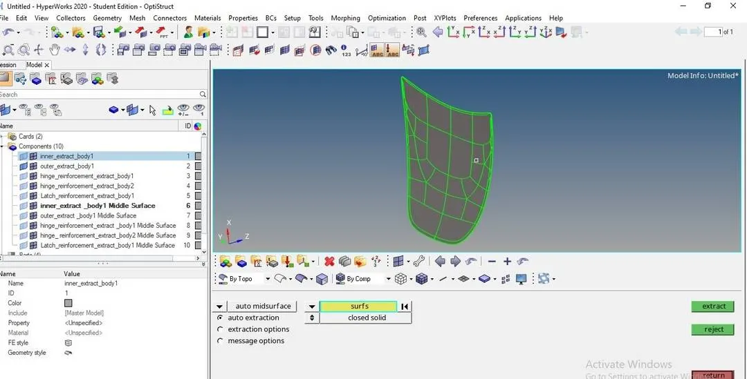
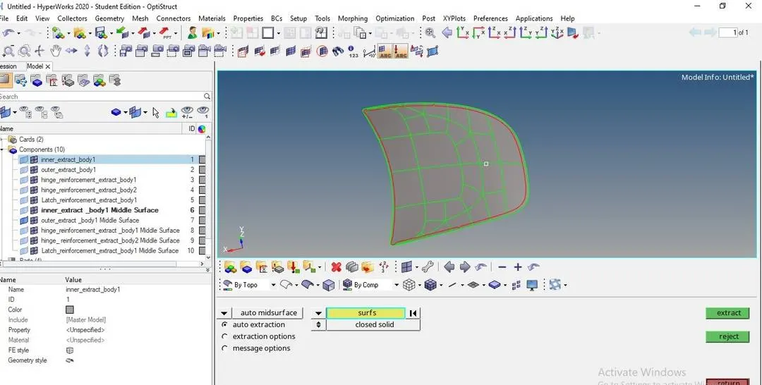
Hinge reinforcement extracted body 1 and 2
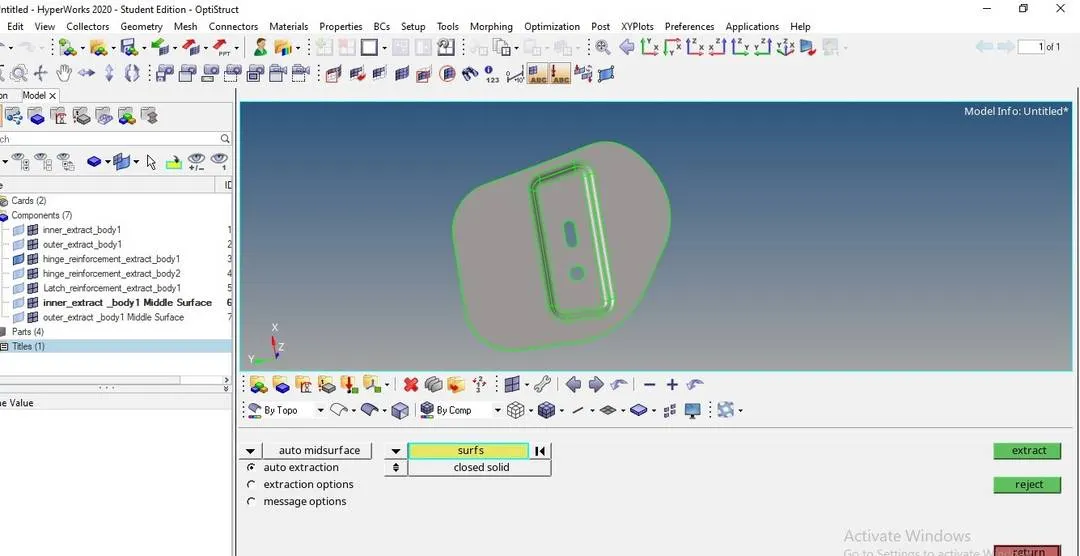
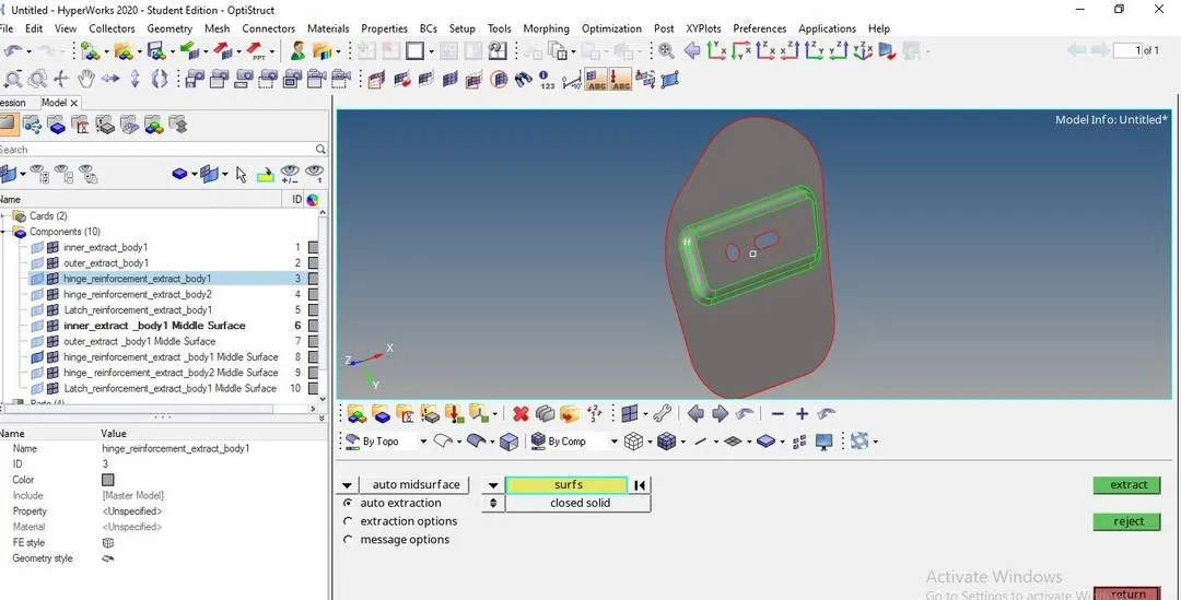
Latch reinforcement extracted body
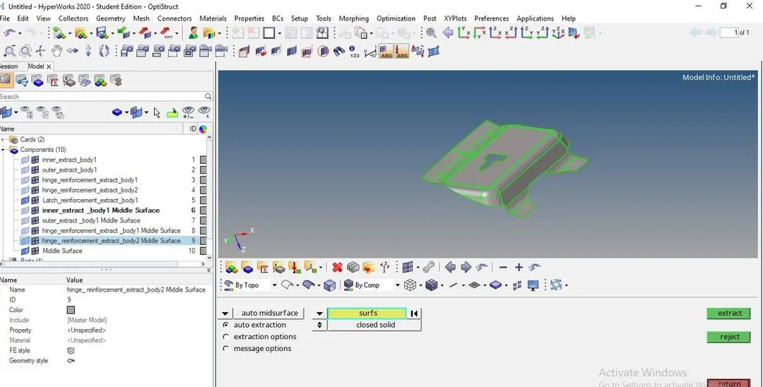
Auto clean-up:
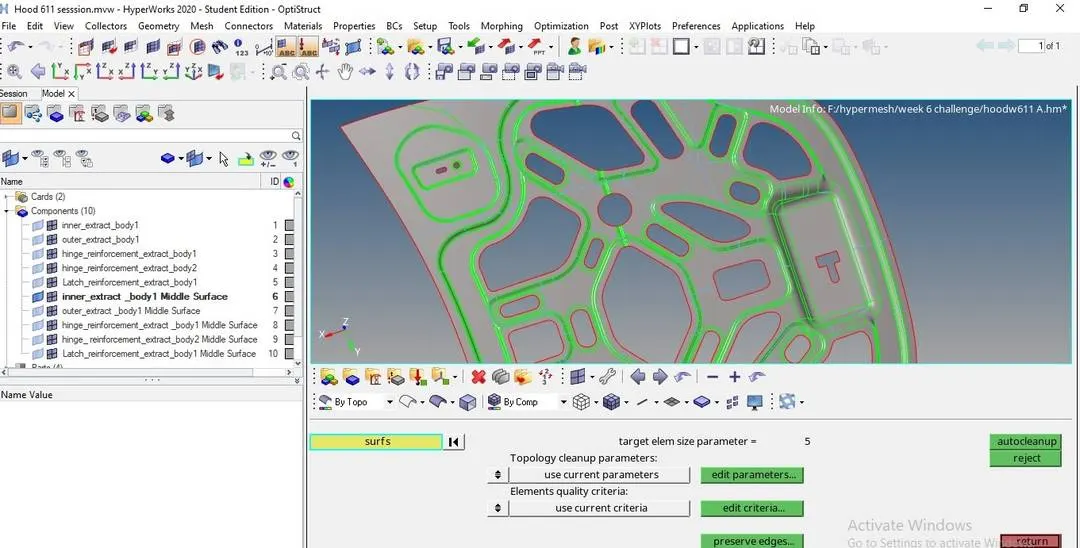
Cleanup operations include the equivalencing of "red" free edges, fixing of small surfaces (relative to the element size), and detection of features such as beads. It also performs specified surface
Editing or defeaturing operations like the removal of pinholes (less than specified size), removal of edge fillets, and the addition of a layer of washer elements around holes.
The Autocleanup panel performs the geometry cleanup portion of the BatchMesher and is available in interactive mode for ease of use. Changing or defeaturing the model to preparing it for meshing and enabling the all extracting option to consider.
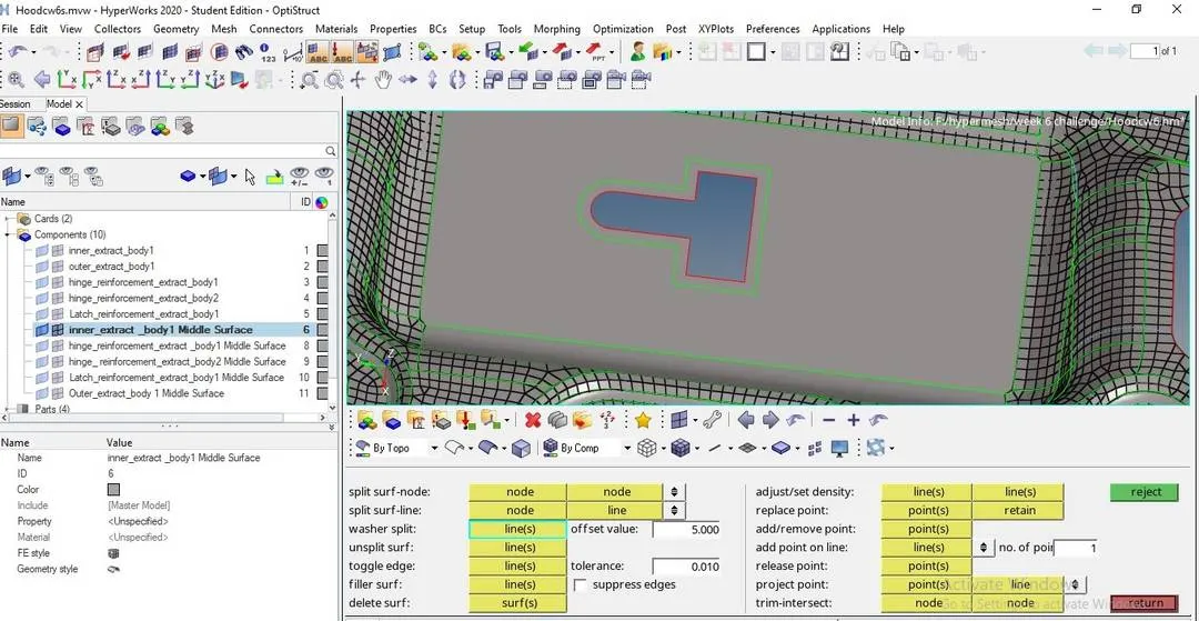
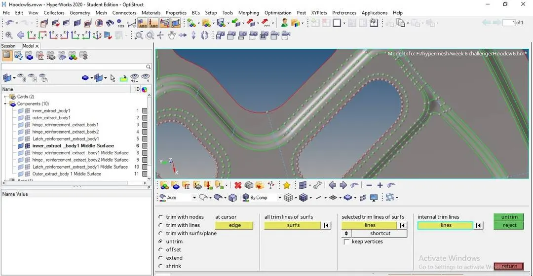
We can un-trim the washer splits as single and before we give washer split trim or untrim it we have to assign the offset value . As per the elemental criteria.
We can de-feature the number of washer splits into single here. Geometry > quick edit > washer split with offset value.
Meshing: Creating the mesh on 2D surface using auto mesh option here. Before we create the meshing we need to edit he criteria by using F12 in the keyboard or preference > criteria, parameters.
Size and Bias.
Use the Size and Bias subpanel to perform size and bias meshing, a flexible and powerful meshing method. A minimum of inputs are required for the element criteria settings.
Size and biasing meshing produces a mesh with consistent element size. If meshed interactively, the number of elements (element density) node spacing (biasing), element type and mesh style can be modified for each surface face and edge.
Use the Auto mesh panel to generate a mesh of plate elements using surface geometry or existing shell elements to define the mesh area.
Mixed:
Uses quads primarily, but inserts trias when making density transitions, resulting in improved mesh quality. I have used mixed elements here to improve the mesh quality and it’s easy to work on surface mesh.
Set the options in the panel in any order that you feel comfortable using. Moving from subpanel to subpanel will not cause you to lose work. When you are finished making all your selections, click mesh to start the meshing process.
- Set the panel mode by selecting the appropriate subpanel.
- Select the meshing method by setting the entity selector to surfs or elements.
- Make the required element criteria settings.
- Set any algorithm options.
- Select the area to be meshed using the entity selector and any extended selection methods
2D > mesh > mixed > elements size
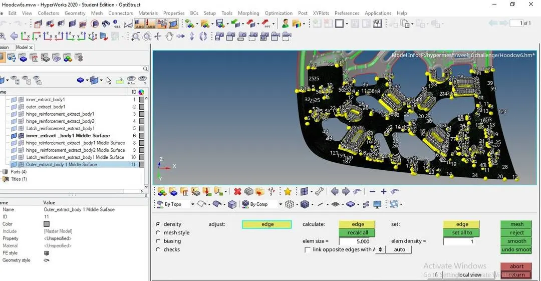
We need to edit the criteria file setting as per the quality criteria given before we mesh the surface. We have option here to select the element type like mixed, quad and quad only etc.
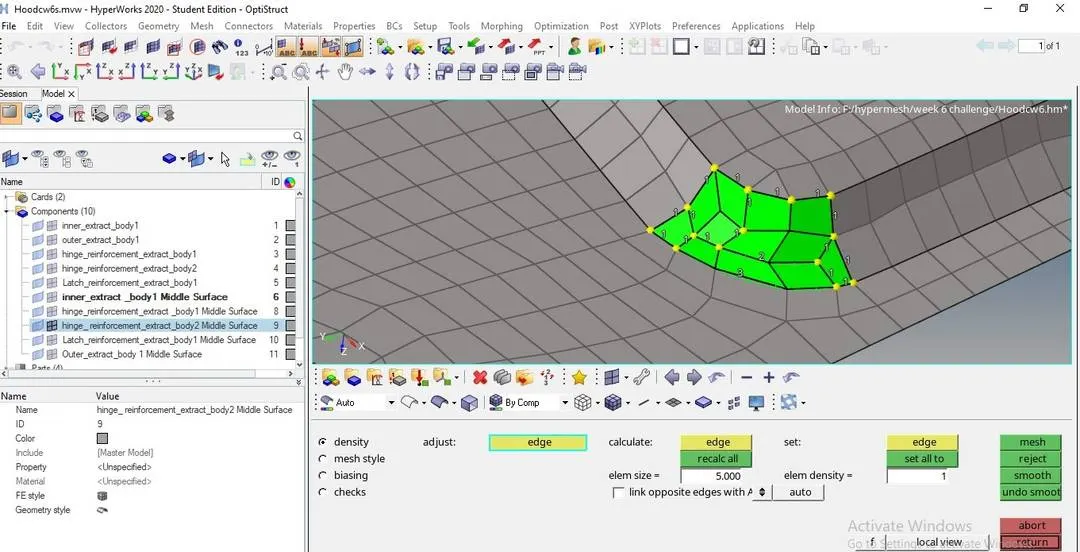
Auto-mesh the surface to get the mesh flow smooth and align ,by repeat the re-mesh again wherever the mesh flow is not align . This is one of the way to get the mesh flow align by re-arranging the elements.
Quality index:
Criteria settings are stored and retrieved using a criteria file. You can save the results from the Quality Index (QI) panel to a summary file.
When you open the Quality Index panel, Hyper Mesh changes the color of the elements according to how well they adhere to the pre-set quality requirements, rather than according to their component or any other visualization mode chosen.
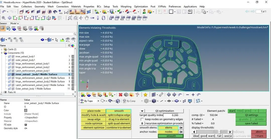
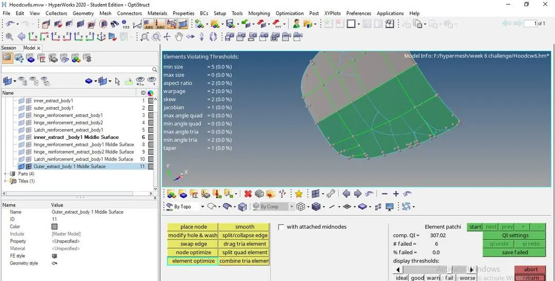
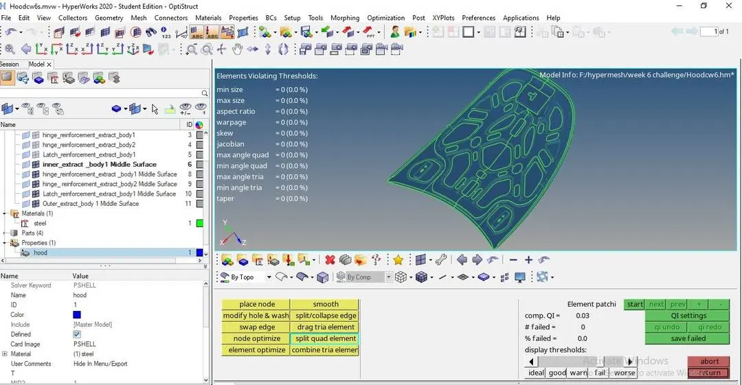
Clean up tools: another method to fix the mesh flow using clean up tools in the quality index. Open the temporary QI Cleanup Tools secondary panel, where you can manually alter the placement of nodes to improve local quality.
Clean up tool helps us to make the element manually.
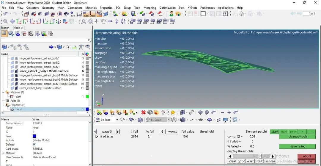
We can see the quality index in the below image how the values are represented as percentage and fail values.
Color legend: Change the color that elements highlight when they fall within each quality category. Each color represent the value of the quality criteria.
Before mesh clean up
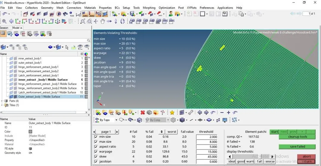
Cleanup tools:
The Quality Index Cleanup Tools secondary panel's layout changes dynamically depending on the cleanup tool you select.
To meet the quality these cleanup tools make use to change or modify the elements and node in particular direction and place, it helps to reduce the errors.
Place node: To move nodes along the surface or normal to the surface.
Modify the hole or washer tool: To modify the elements or nodes around the hole without changing the hole radius and also moving the washer elements to modify the radius and angular movement of the element.
Swap edges: Use the Swap Edge tool to consider the elements to which the edge belongs, and find alternative orientations for it. To improve the mesh quality and rectify the fail elements. For a pair of trias, there are two possible positions for their shared edge. For a pair of quads, there are three possible positions. For a quad and a tria, there are six possible positions.
Smooth: To improve the mesh quality of surface based mesh.
Node optimize: Use the Node Optimize tool to automatically move a selected node to optimize the overall quality of its surrounding elements. The options along surface, normal to surface, and along and normal to surface work exactly as described for the place node tool. The only difference is that node optimize moves the node automatically, while place node requires you to choose the location manually.
Element optimize: Use the Element Optimize tool to automatically optimize the shape of the selected element and the elements surrounding it. It is similar to Node Optimize, except that its effects are wider-spread.
Drag tria: To move the trias from one location to another or out of location.
Split quad: sometime quad elements are out of size then we can split the quad by click on the quad element.
Edit element also used here to do similar kind of function, like create, combine and split. 2D> edit element>create (quad, trias, hexa. Etc.) Or combine or split the element.
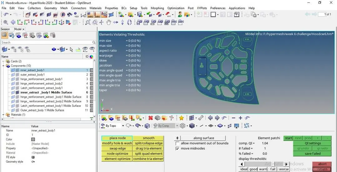
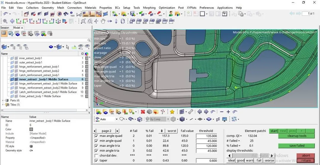
Save the failed elements then we can retrieve the elements to rectify the error in that particular elements. Quality > clean up tools > save failed > mask > elements > retrieve > mask > reverse.
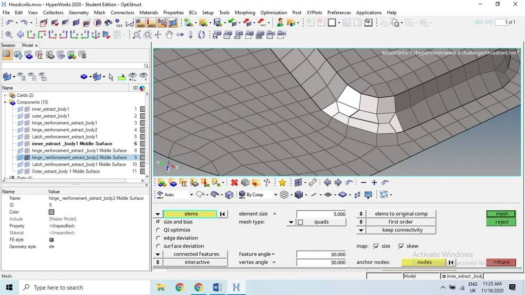
Re- auto mesh or rearranging the mesh pattern where ever the mesh flow is not smooth by selecting the elements and click on the mesh option .we repeat the same steps to improve the mesh quality.
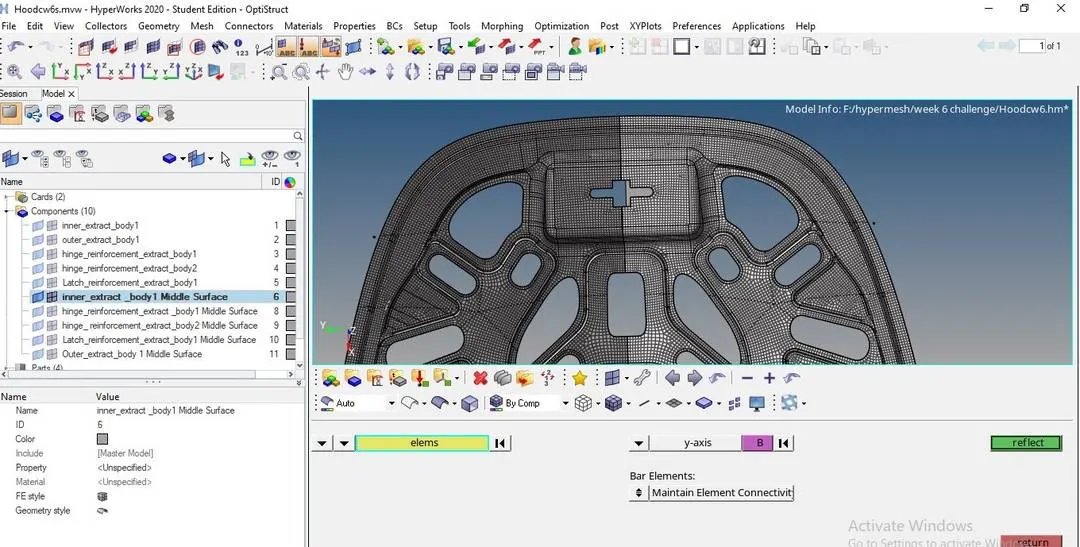
Component is symmetry so we can made into two symmetrical, Due to complexity of the component first we have made the component symmetry through the geometrical tools. Geometry > trim surface plane or distance using two point. After marking the middle point of the component, use surface symmetry option where we can trim the surface with line two symmetrical surfaces.
Tools > reflect > elements > axis(x,y and z or surface normal or nodes N1, N2 N3 and B etc.)
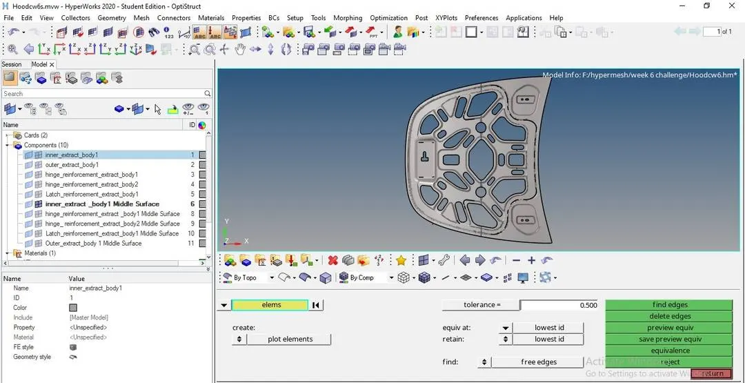
Duplicates: we need to delete the duplicate node after reflecting the surface. Select the elements tools > edges > select the elements and change the tolerance value as 0.5 then click on equivalence. In tools we have check element option to identify the duplicates because it should be less than the 10Million nodes count FE. After deleting the node we can check the node count using the count option at tools.
Tools > Check elements > duplicate elements > save failed then go to the delete > elements, right click on mouse take us to option retrieve (the save failed) below we can see the number of duplicate elements then click on delete entity.
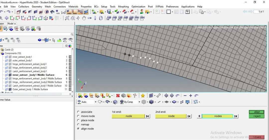
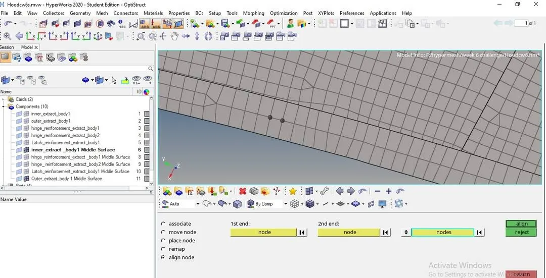
Geometrical errors after meshing: Use the Align Node subpanel to snap one or more nodes to an imaginary line connecting two other selected nodes. Any number of nodes may be aligned once a line is defined.
We can see the how the align node works, Geometry > node edit > align. Select the node 1 and 2 where you want align then select further wherever the misalign node present then click on align. We can observe in the below image.
Model check:
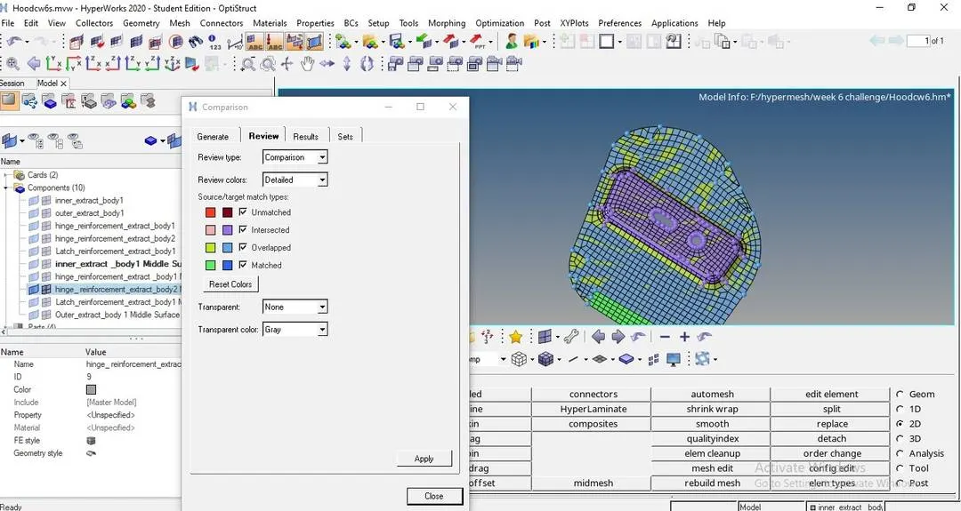
Mesh > check > elements > comparison. To check the elements and surfaces which are unmatched and, intersected, overlapped and matched with different colors. Wherever the red color represents it is unmatched element.
Use the Normals panel to display and reverse the normals of elements or surfaces. The orientation of element normals can also be adjusted. The normal of an element is determined by following the order of nodes of the element using the right-hand rule.
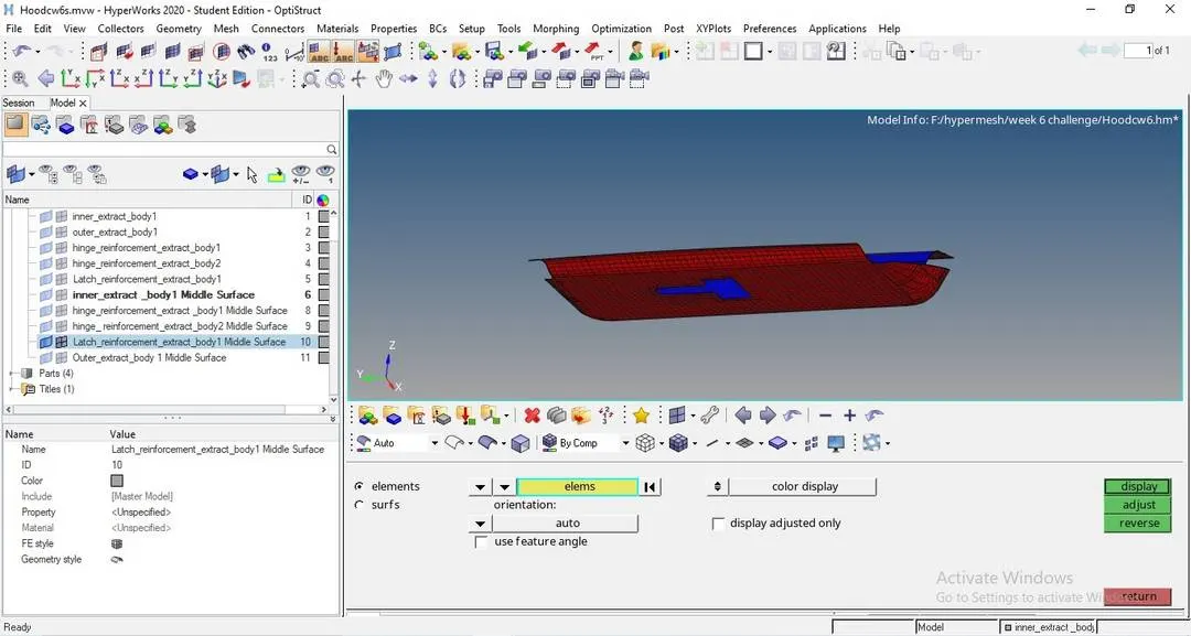
Another model check is display normal with color display and vector display, here we can check the whether all the elements are same side .which means each surface must consist single color as we see in the below image. If anywhere the elements are having different color then select those elements make them reverse by selecting reverse option at right side of the panel.
Tools > normal > select elements > display 2D element> color display > click on display> each side component must have same color if not select the elements then make reverse by clicking on reverse option.
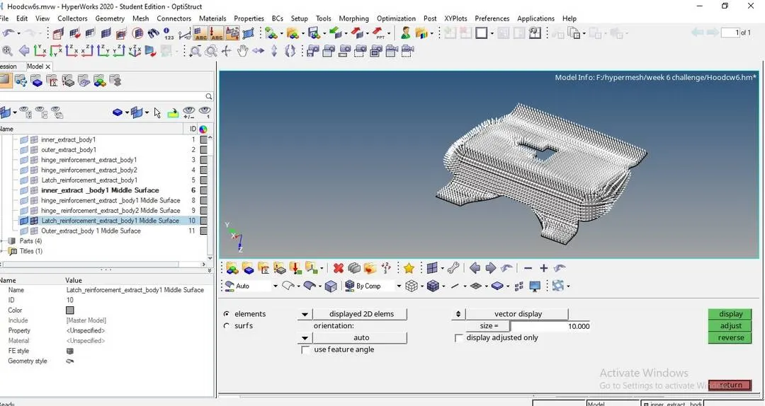
Another way to check the normal is vector display with size. Here all the vectors must point in one direction on the surface
Tools > normal > select elements > display 2D element > vector display
Dependency:
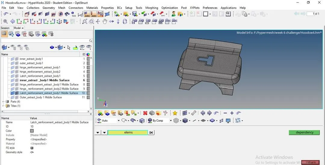
Use the Dependency panel to find nodes that have their degrees of freedom removed by a constraint or MPC (multiple point constraint) more than once. By identifying and correcting such dependencies prior to solving, solution errors can be avoided. We can see zero multiple dependencies in the below image.
Tools > dependency> elements > select the elements below left side of the window it shows the number of dependency elements.
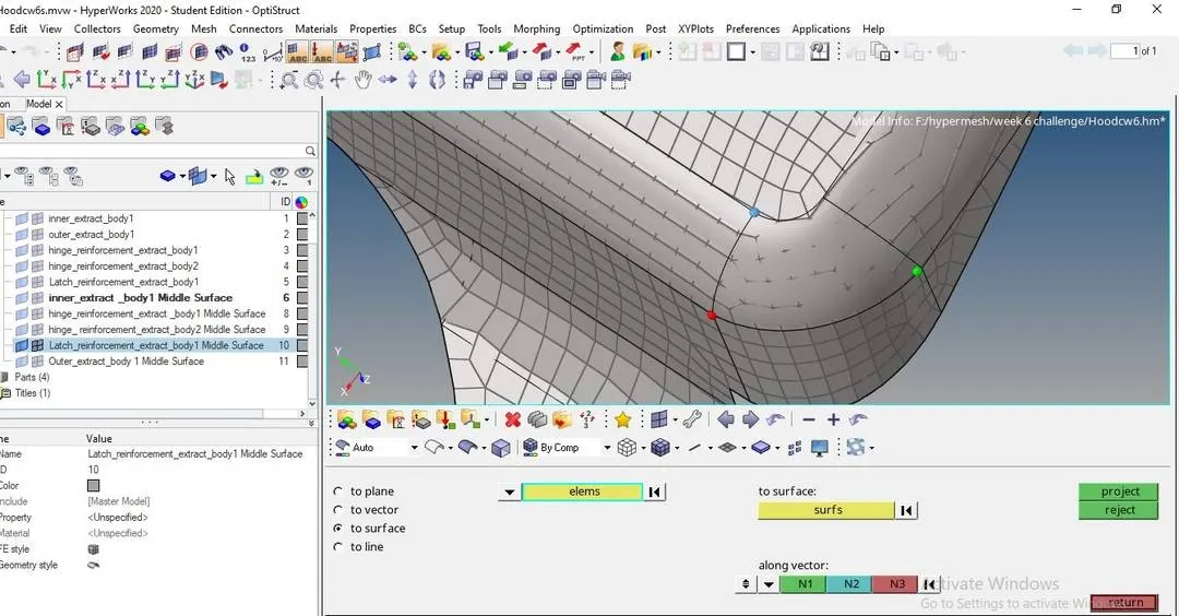
Projection of elements and nodes: Use the Project panel to project data entities to a plane, vector, surface, or line. Tools > projection > to surface > selecting the elements > along vector N1 N2 N3 > selecting the other attached surface.
Final images of the hood
Outcomes:
- Learned to extract the auto-middle surface for complex models
- Learned to mesh for complicate model with intricate geometrical shapes.
- Achieved quality criteria with less tria percentage using cleanup and other tools.
- Learned and understand the how to repair the mesh as well as geometry after reflection.
Conclusion: 2D surface meshing on hood model and middle surface extraction for all components separately is done as per the given quality criteria.