Week-6 Calculate the Stretch Ratio by comparing the ELFORM (-2,-1,1,2) with Ogden_Material Model.
Stretch Ratio Calculation
Aim: To compute the stretch ratio in a hyperelastic material specimen under uniaxial tension, using different element formulations.
Theory: In solid mechanics, the general formula of stress is given by:
`sigma` = Force/Area = F/A..........................(i)
This formula gives what is known as the engineering stress i.e. the stress is computed with respect to the initial cross-sectional area of the specimen. However as the specimen is loaded, its cross-sectional area goes on decreasing (in tension) and by equation (i), the stress in the specimen is actually higher than that given by engineering stress.
`sigma` (true) = F/Ai = Force /instantaneous area...............(ii)
Engineering strain is given by:
`epsilon` = change in dimension/original dimension
= `delta` L/L0.............................(iii)
The relation between engineering stress and true stress is given as:
true `sigma` = `sigma` * (1 + `epsilon`).............(iv)
The relation between engineering strain and true strain is given by
true `epsilon` = ln(1 + `epsilon`)......................(v)
where (1 + `epsilon`) = 1 + `delta`L/L0 = L/L0 ..........................[L = final length or dimension at the end of loading]
Therefore, from equation (v), the stretch ratio can be computed as:
stretch ratio = exp(true`epsilon`)...................(vi)
From equation (iv), the analytical engineering stress can be written as:
`sigma` = true `sigma`/(1 + `epsilon`) = true `sigma`/stretch ratio............(vii)
Geometry and mesh: A cube of 10mm*10mm*10mm with 10 elements along each dimension was created using Mesh>Shape Mesher> Box_Solid.
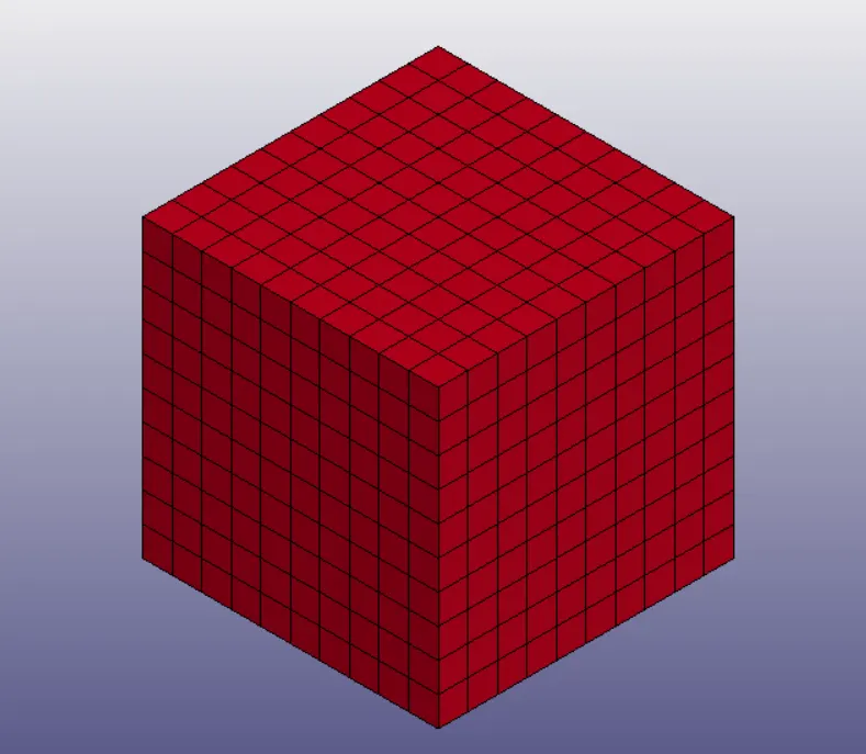
Fig 1: Meshed solid block specimen
For this analysis, 4 different simulations were run using 4 different element formulations:
- ELFORM 1 => Constant stress solid element
- ELFORM -1 => Fully integrated S/R solid for elements with poor aspect ratio, efficient formulation
- ELFORM 2 => Fully integrated S/R solid
- ELFORM -2 => Fully integrated S/R solid for elements with poor aspect ratio, accurate formulation
Constitutive Material Model: To simulate the behaviour of vulcanized rubber, MAT_077O or MAT_OGDEN_RUBBER was assigned to the cube with a density of 0.001gm/mm3, poisson's ratio of 0.45, and other material properties as shown in the card image in Fig 2.
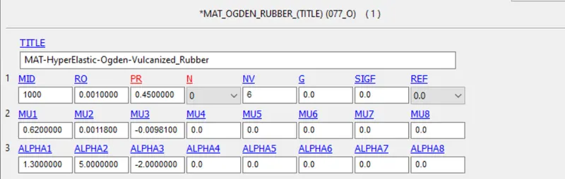
Fig 2: Ogden Material model card parameters
Boundary Conditions: Three sets of Single Point Constraints are defined-
- all degrees of freedom fixed for all the nodes of the bottom face (Fig 3),
- Y-translation constrained for the node-set shown in Fig 4,
- X- translation constrained for the node-set shown in Fig 5
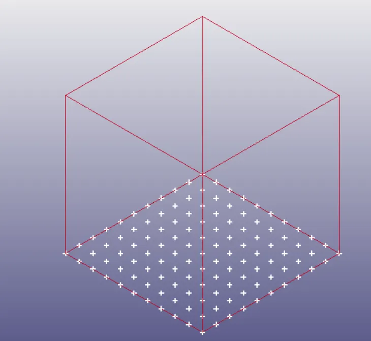
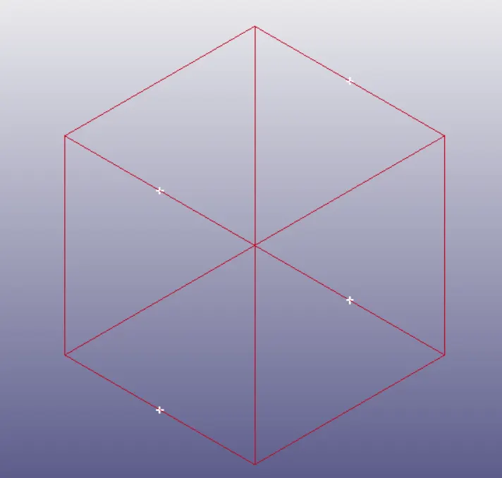
Fig 3: Nodes constrained in all DOF Fig 4: Nodes constrained in Y-translation
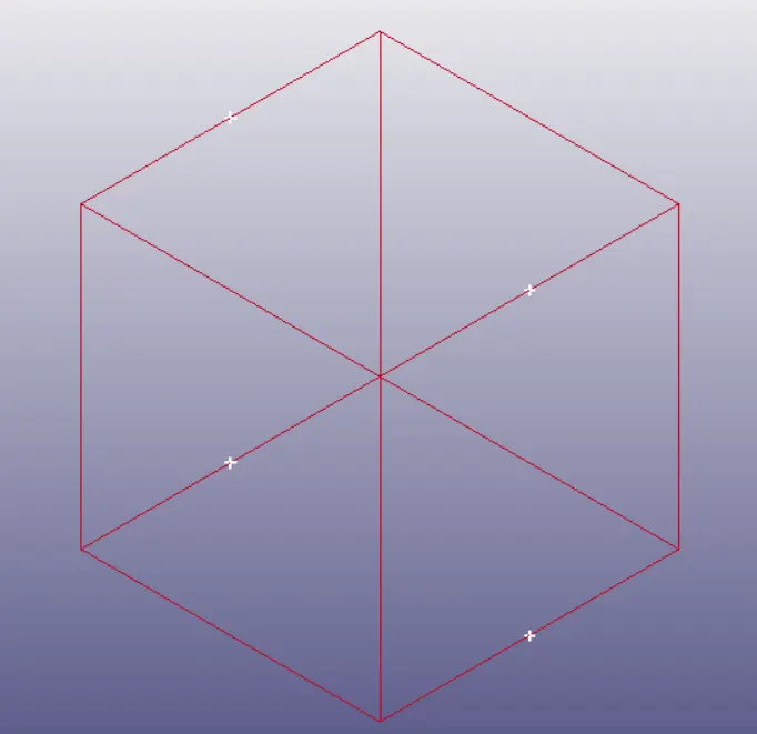
Fig 5: Nodes constrained in X-translation
All the nodes of the top face are provided with a displacement of 50mm in the positive Z direction through a load curve (Fig 7).
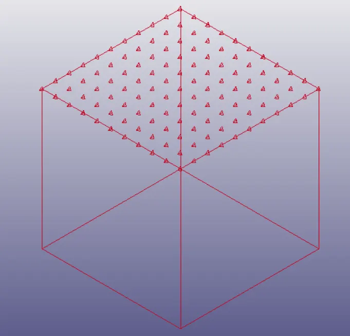
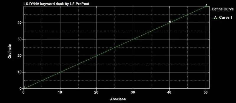
Fig 6: Nodes provided with displacement Fig 7: Displacement vs Time curve
Solver: For this non-linear static analysis, an implicit solver was used (IMFLAG =1 in Implicit _General) to get more accurate results and equilibrium between the external and internal forces. The nonlinearity arises from the hyperelastic material model as well as the large deformation that takes place due to such material definition. To account for this non-linearity, time steps are introduced - initial time step of 0.5ms, a minimum time step of 5e-4ms, and a maximum time step of 1ms is defined using the Implicit_General and Implicit_Auto cards.
11 iterations are defined for convergence with a window of 5 iterations (above or below the optimum). The BFGS update with an optional line search solver is used. The stiffness matrix is set to be updated every iteration with the matrix being reformed after every 11 iterations (in case of convergence failure).
The displacement convergence tolerance criterion is set to 0.001 times the total displacement at the time step (DNORM =2). This makes for quick computations but somewhat less accurate results (than using incremental displacement as the convergence criterion).
The simulation is given a run time of 50ms.
Results: The animation results from the runs show an extension in the specimen analogous to a uniaxial tensile test. This ensures that the stress and strain in all the elements are the same. From the time history files, the stress and strain in Z-direction for element H-956 is plotted (data points are saved). These values of stresses and strains for the time steps give the true stress and strain developed under the given loading conditions. From there, the stretch ratio and nominal engineering stresses are computed using equations (v) and (vi) and the results are plotted.
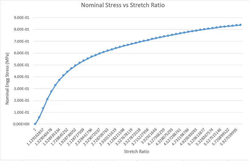
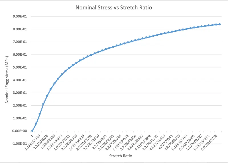
Fig 8: Nominal stress-Stretch Ratio Plot for ELFORM 1 Fig 9: Nominal stress-Stretch Ratio Plot for ELFORM -1
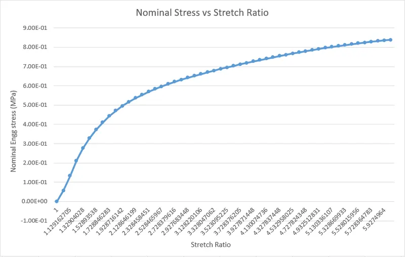
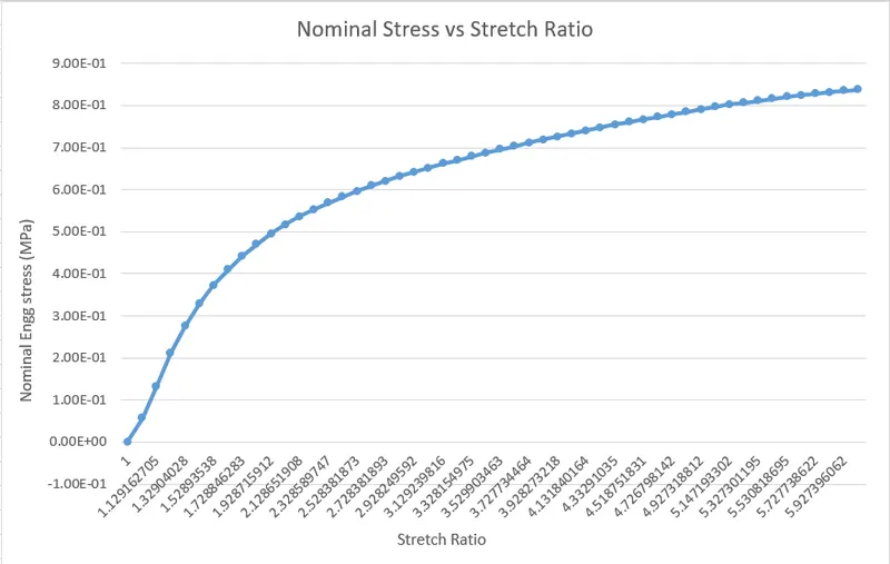
Fig 10: Nominal stress-Stretch Ratio Plot for ELFORM 2 Fig 11: Nominal stress-Stretch Ratio Plot for ELFORM -2
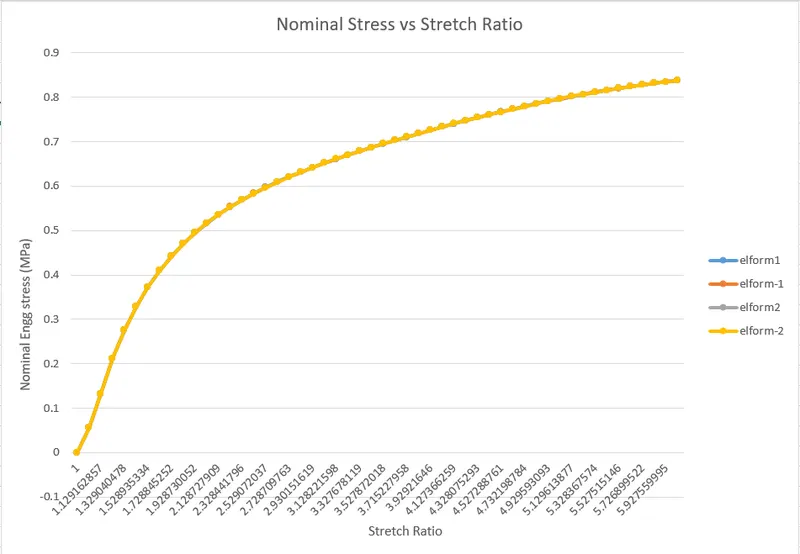
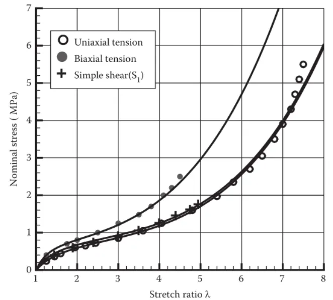
Fig 12: Combines Nominal stress-Stretch Ratio Plot Fig 13: Experimental Stress-Stretch Ratio plot
Conclusion: From Fig 8, 9, 10, and 11, it can be observed that for the given displacement of 50mm, a stretch ratio of 5.99 is obtained. A stretch ratio of 5 is hit at almost the 40th millisecond or at 40mm of imposed displacement. For a given stretch ratio, the nominal stress in the specimen does not differ much with varying the element formulations. Any variation observed is minute. Hence the combined plot of stress-stretch ratio for all the element formulations seems to be a single line (Fig 12). When compared to the experimental plot (uniaxial tension) of the same parameters, it can be seen that the nominal stress in the experiments at a stretch ratio of 5 is almost twice as much as in the simulations - 0.8 MPa in simulation and 1.6MPa in the experiment.