Calculate the Stretch Ratio by comparing the ELFORM (-2,-1,1,2) with Ogden_Material Model using Implicit solver
AIM: To compare the results for the simulation using element formulation ELFORM= 1,2,-1,-2. for a tensile test of a cube using an implicit solver.
ABSTRACT: Here we have taken a cube of size 10x10x10 mm and tried to simulate the results for the tensile test using an implicit LS-Dyna solver. Also we will compare the results for the element formulation ELFORM= 1.2.-1,-2. The material used here is Ogden_material which is the hyperelastic material model used mainly for the foam and rubber type of material.
THEORY:
Ogden Material model: These are the highly elastic material which can recover from there deformation when subjected to very large strains. These material models are most common for modeling rubber kind of material. the stress-strain relationship is derived from the strain energy density function. No linear relation between stress and strain
Ronald Rivlin and Melvin Mooney first developed hyperelastic models, the Neo-Hookean & Mooney-Rivlin-solid. other than these Ogden and Yeoh Arruda- Boyce models are very famous and widely used in industries.
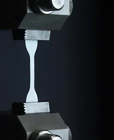
we can get the stress-strain curve using three types of Test i.e. 1) uniaxial test 2) bi-axial test 3) Planer test.
if we have all three test data then the material model will be very accurate. but here in this challenge, we are going to stick with the uniaxial tensile test.
METHODOLOGY:
To get the following simulation we need to follow certain steps:
- Open the Odgen material card (.k formate file) given in the question
- Create a solid cube of 10x10x10 with 10 elements in each direction using 'Shape Mesher' under 'Element and Mesh' module.
- Define the section card and material same as Odgen then assign that to the part solid_cube.
- Give the boundary condition(SPC) for the cube representing the tensile test behavior.
- Set the prescribed motion as displacement in one of the direction
- Set the control card for the implicit solver and database cards for outputs
- save the .k file and run the simulation(LS-run)
- Run the binary file to observe the results.
- change the 'ELFORM' inside the 'Section card to see & compare the results.
IMPLICIT SOLUTION APPROACH
Our approach to solving this problem will be implicit as there are no internal effects [m=0] and the load rate is very slow therefore low strain rates. Also, the growth of stress is only the function of strain(NOT strain rates). Also, there is no contact condition, so it best to solve such a problem with the implicit approach that gives much accurate results.
PROCEDURE:
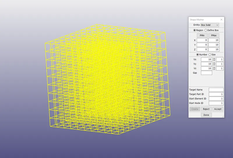
Create a solid cube of 10x10x10 with 10 elements in each direction using 'Shape Mesher' under 'Element and Mesh' module.
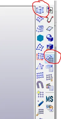
The cube created is consisting of 1000 solid hexa elements. keep the Pmax value as 10 10 10 for xyz to make 10 mm cube.
Define the section card and material same as Odgen then assign that to the part solid_cube.
Define the solid section for the SOILD_CUBE and assign the ELFORM as 1 [Accept>Done].
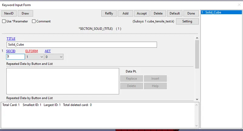
Keep the material card same as the given in the question with MAT_077 and rho value as .001 and poison ratio as 0.45
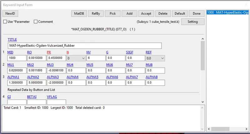
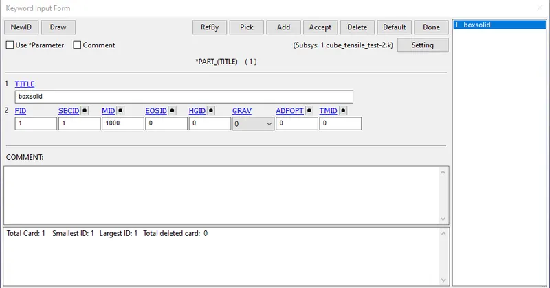
Define the part card
Assign the section_solid card ID:1 and Material_077_odgen: 1000 to define part.
Give the boundary condition(SPC) for the cube representing the tensile test behavior.
So as to perform the tensile test we need to assign perfect boundary condition such that one of the face is fixed in x translation and in all rotational DOF and prescribed dispalcement is given on the other opposite face.
To do so we need to define three single point constraints
1) spc on all nodes of one of the face(yz-plane) and arrest all dof except translation in y and z[100111]i.e. lateral movement of the faces allowed when stretched in x dierction
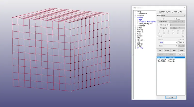
2) SPC on centerline nodes (neutral membrane) on the (yz-plane) for both the faces and arrest all dof except translation in x and z[010111] i.e movement of the neutral fiber along y -axis is and in all rotational dof is arrested.
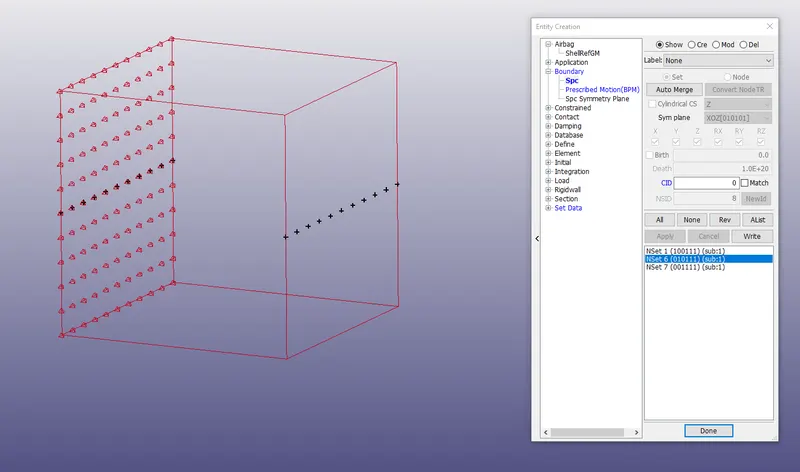
3) SPC on centerline nodes (neutral membrane) on the (yz-plane) and arrest all dof except translation in x and z[001111] i.e movement of the neutral fiber along z -axis is and in all rotational dof is arrested.
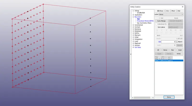
Set the prescribed motion as displacement in one of the direction
As we are going to solve this problem using a implicit solver therefore we will define a prescribed displacement. On the opposite face towards x direction.
To do so we need to assign 3 values
1) select the node and make the node_set assign the NSID
2)VAD = 2 for Displacment
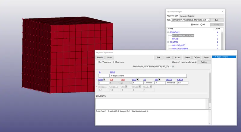
3) Define the LSID: Curve id
Define curve as shown below. either (0,0)(1,50),(1.2, 50) with scalefactor(SF=1) or define graph (0,0),(1,1),(1.2,1) with SF= 50
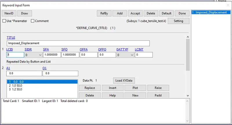
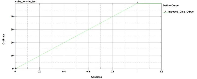
we gave the value for S.F as 50 in our case we need above 5 stretch factor> `lamda= (1+epsi_(engg))-> 5=(1+(dl)/l)`
`(5-1)=(dl)/l=(dl)/10-> 40=dl`
therefore displacement required= 40 +10=50 mm or more to have above 5 `lamda`value
Set the control card for the implicit solver and database cards for outputs
control cards
1)CONTROL_IMPLICIT_AUTO
IAUTO=1:

ITEOPT= 50 ( ITERATION OPTION) AND ITEWIN= 5

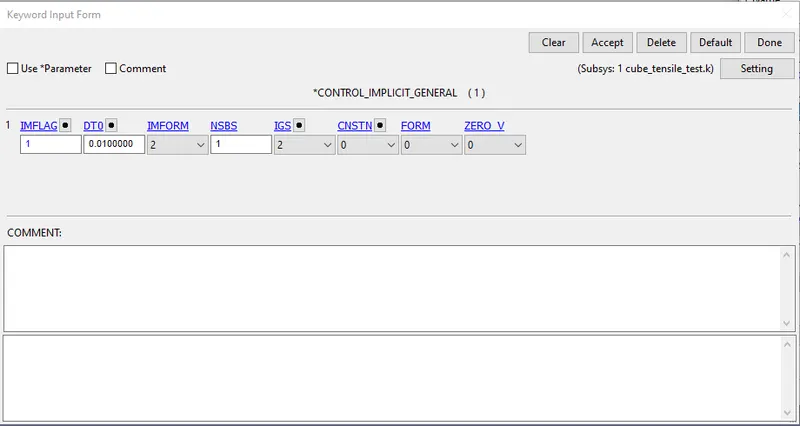
2)CONTROL_IMPLICIT_GENERAL
IMFLAG=1: TO ACTIVATE THE IMPLICIT SOLVER AND SET THE DT0 AS 0.01ms (INITIAL TIME INCREMENT)

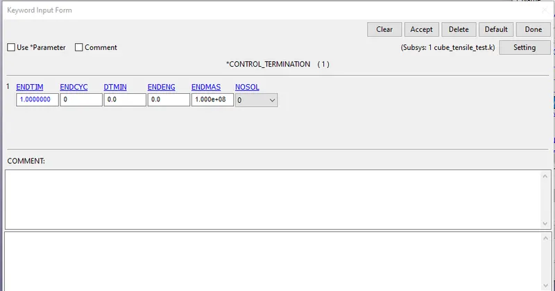
3)CONTROL_TERMINATION
Set the ENDTIME=1ms as the displacement is given for the period of 0 to 1.2 ms
Database cards
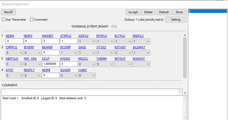
Now we need to define the database card required to do the post-processing of the simulation
1) DATABASE_EXTENT_BINARY : Set the STRFLG =1 (to wite the strain tensor data to d3plotand elout.

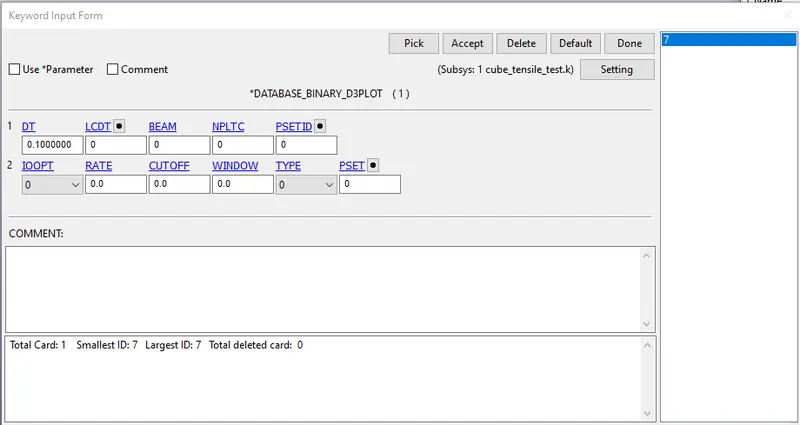
2)DATABASE_BINARY =_D3PLOT: Set the Dt = 0.1 ms [Accept> Done]
Save the keyword file with .k format run the solver and build the d3polt file.
Just change the Element formulation ELFORM in section card to 1,2,-1,-2
- Element formulation 1: Under integrated solid element. low computational time, low cost, need hourglass control.
- Element formulation 2: selective reduced integrated element(full integrated formulation). A bit high computational time than ELFORM 1 and costly .
- Element formulation -1 ,-2: similar to ELFORM 2 but prevent volumetric locking and handle poor aspect ratio.high computational time

CONCLUSION:
Stretch Ratio:
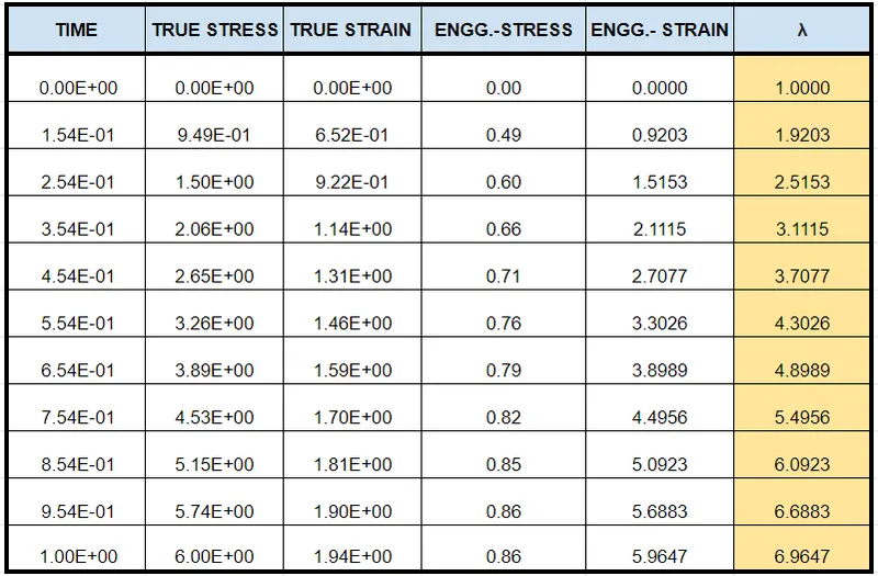
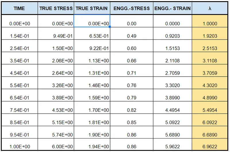
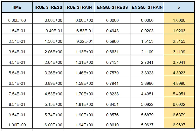
As we know that the `sigma_(true)=sigma_(engg)(1+epsi_(engg))`
also the `epsi_(true)=ln(1+epsi_(engg))`
and the stretch ratio `lamda= (1+epsi_(engg))`
The following are the results from changing the ELFORM :
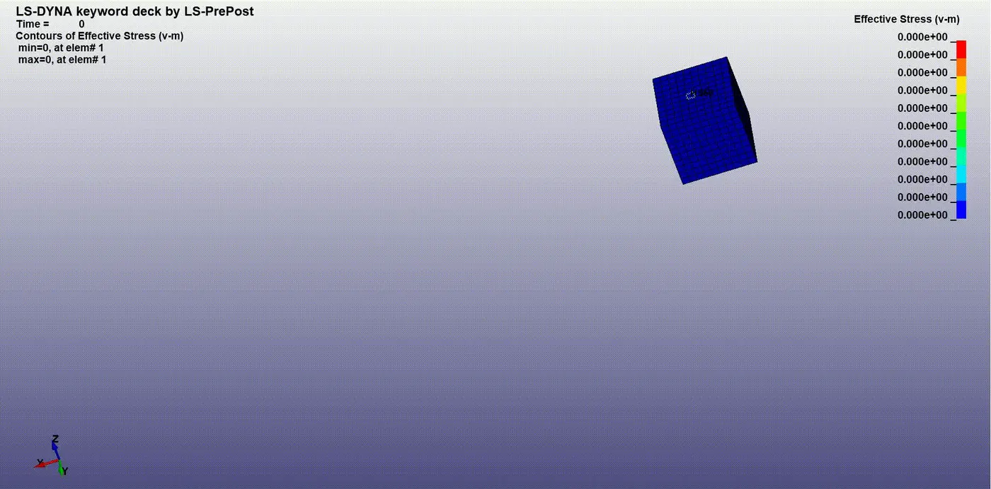
1)ELFORM= 1
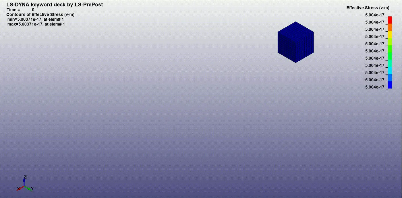
2)ELFORM=2
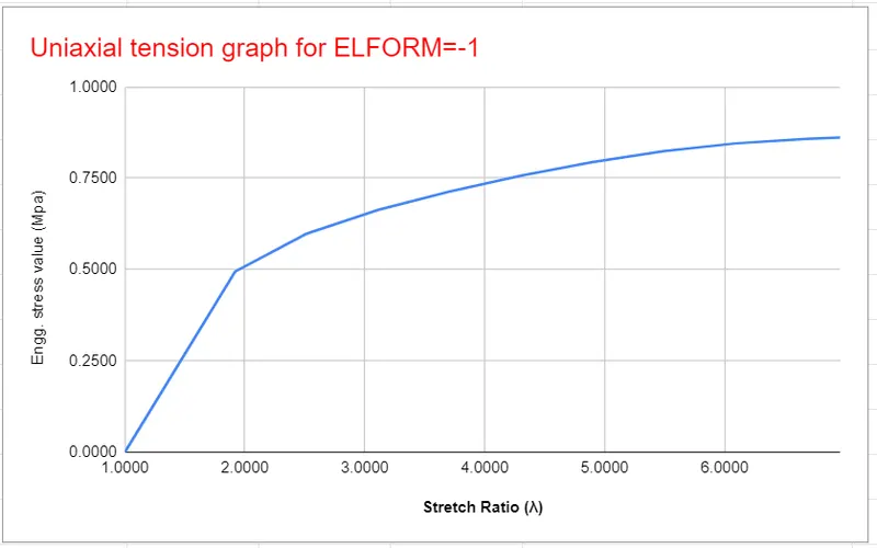
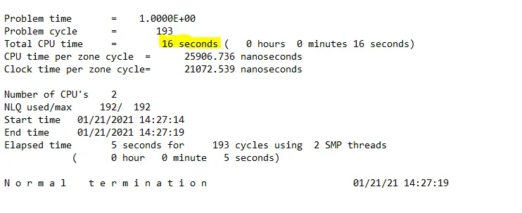
3) ELFORM=-1
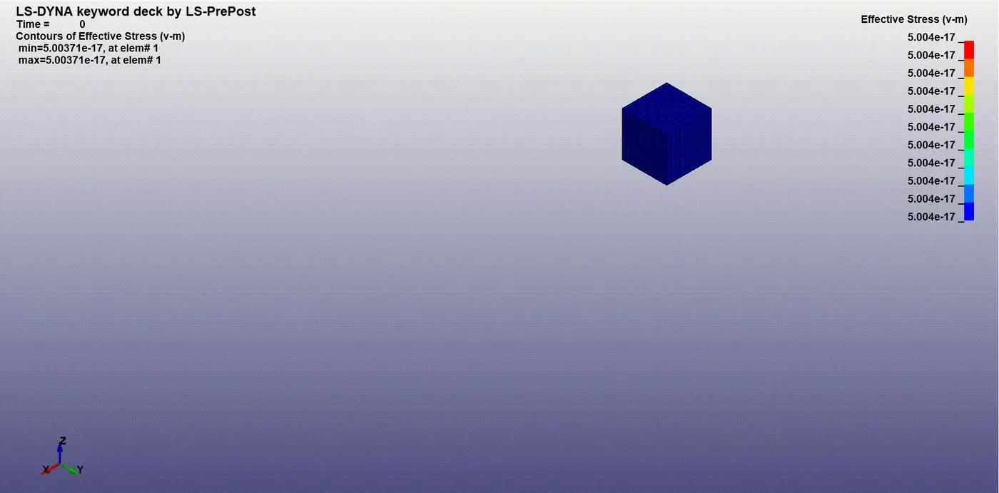
4)ELFORM= -2
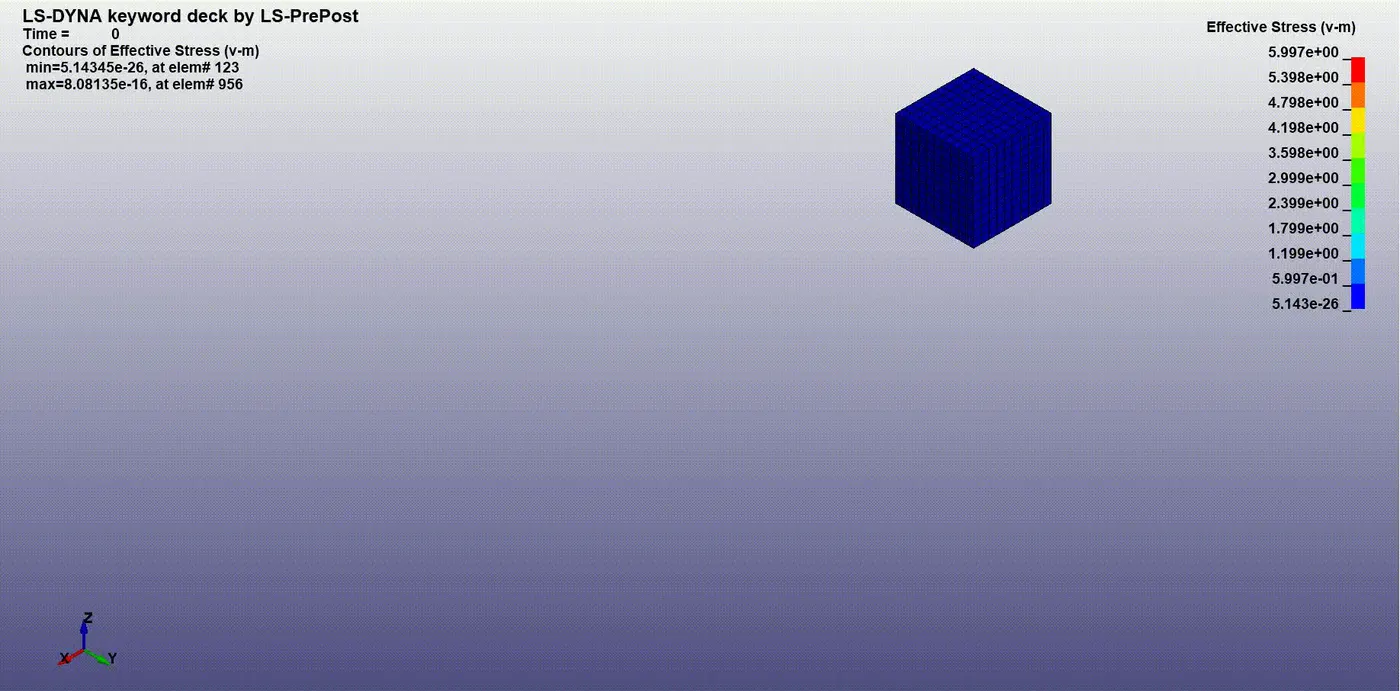
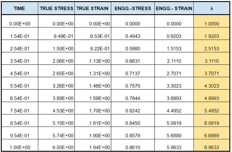
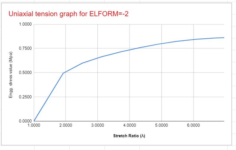
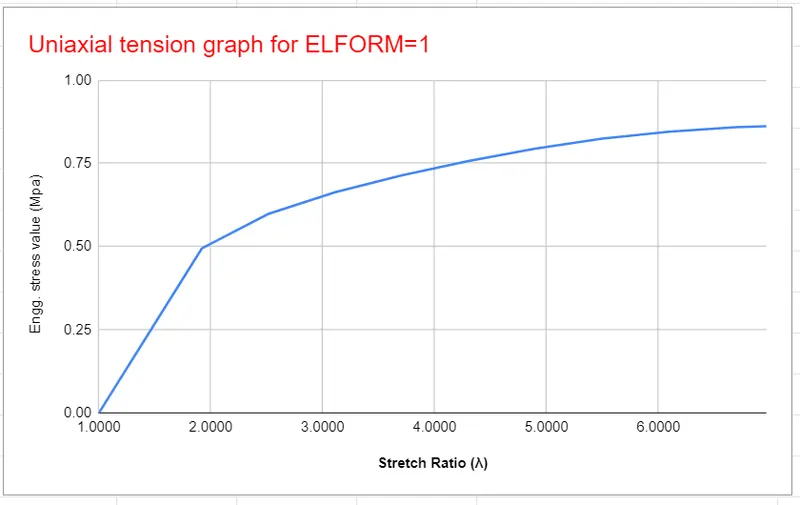
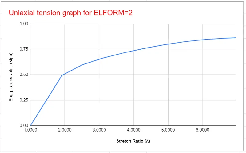
As from the above all the simulations with different ELFORM, we see a very similar pattern of the graph with maximum true stress ~6 Mpa and Engg. stress ~0.86Mpa and True strain~ 1.94 and Engg. strain value as ~ 5.94. The stretch factor as per the requirement is ranging from 1 to ~7 (above 5 )
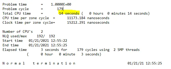
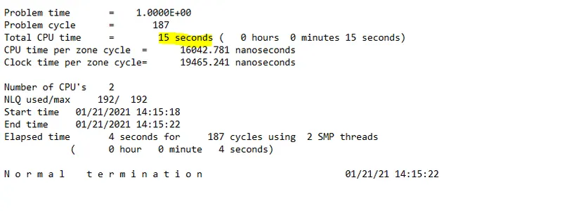
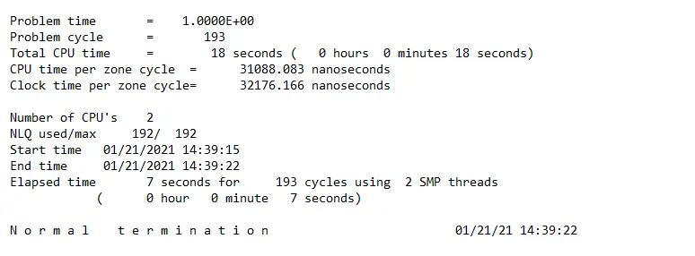
The CPU time required by different element formulation is different, lowest for ELFORM=1 i.e 14sec and highest for ELFORM=1 i.e 18 sec this because with ELFORM=1 it is the default option with one point integration. while others are fully integrated shell elements with higher computational time. The differences encountered are very less because of the low complexity of the model we are trying to simulate.
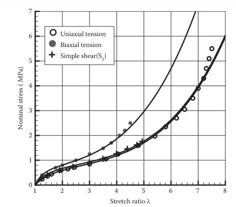
if we compare the uniaxial curve with the curve we got from different ELFORM values we can see a bit of similarity at the start of the graph i.e till 0.8 stress value.