Week-6 Calculate the Stretch Ratio by comparing the ELFORM (-2,-1,1,2) with Ogden_Material Model.
OBJECTIVE: -
Given is a Ogden material card which is hyper elastic (rubber). Create a 10x10x10mm solid mesh and run a pure tensile run on it with stretch ratio of 5. Compare different element formulations of solids 1,-1,2,-2 and plot engineering stress vs stretch values.
PROCEDURE: -
l Here we will perform a simple tensile test on a 10x10x10 mm cube with Ogden material model.
l To see the behavior of element formulation, we will work on different cases as per different element formulation as given below.
1. CASE 1: Element Formulation (1)
2. CASE 2: Element Formulation (2)
3. CASE 3: Element Formulation (-1)
4. CASE 4: Element Formulation (-2)
Ø CASE 1: ELEMENT FORMULATION (1)
l First of all open the L S DYNA Keyword file named as “Ogden_Material.k” in LS-PrePost.
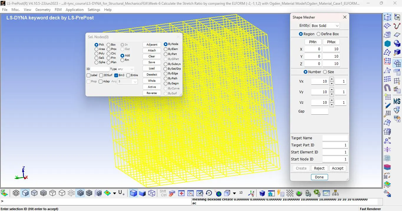
l Create a cube of 10x10x10 mm with help of “Shape Masher” in “Elements and Mesh” as shown below:
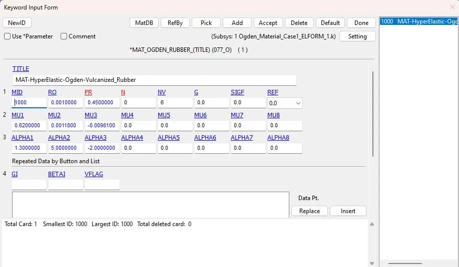
l Create the ogden material as per below.
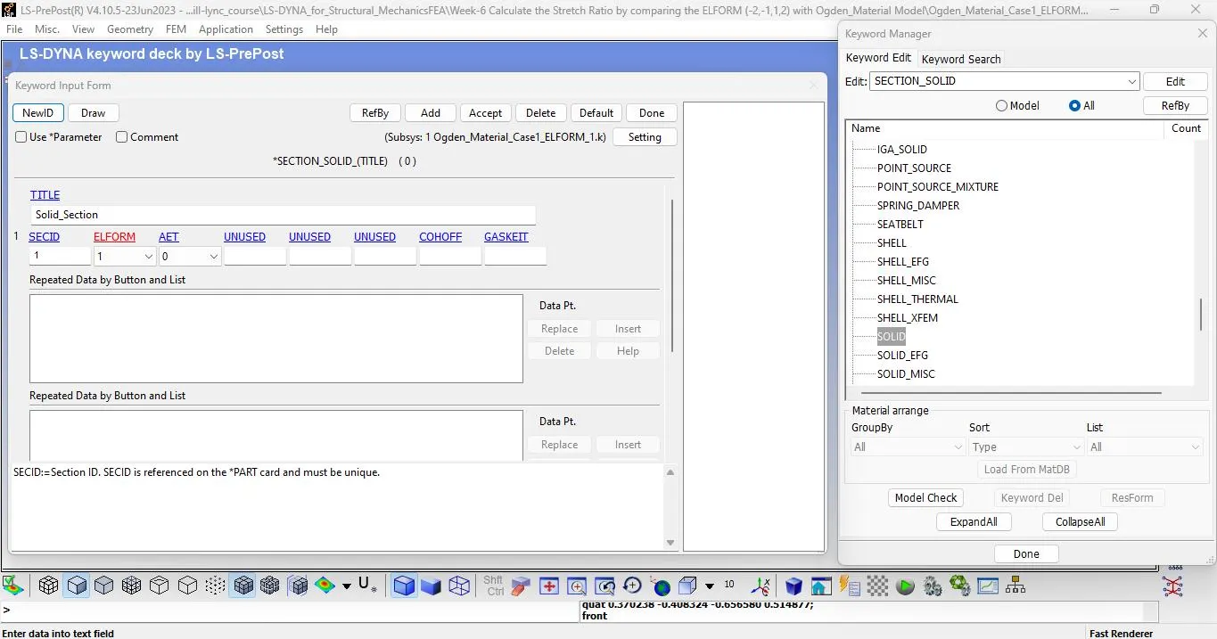
l Create a Section card for the cube and assign the element formulation criteria as per the case as given below
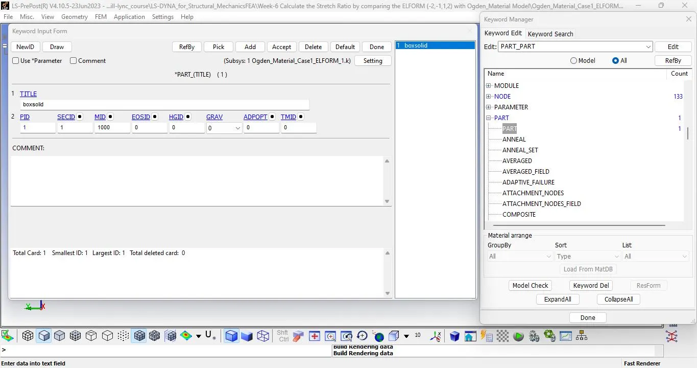
l Assign the material & section to the part.
l Now create boundary condition to fix the nodes.
l Fix the bottom of the cube and give motion to the set of the nodes on the upper faces.
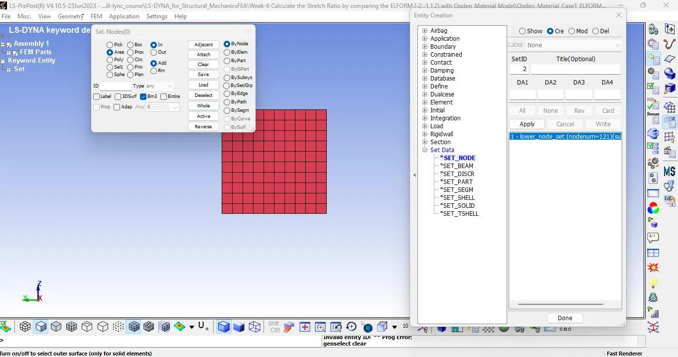
l Go to model & part - create entity - set data - set node.
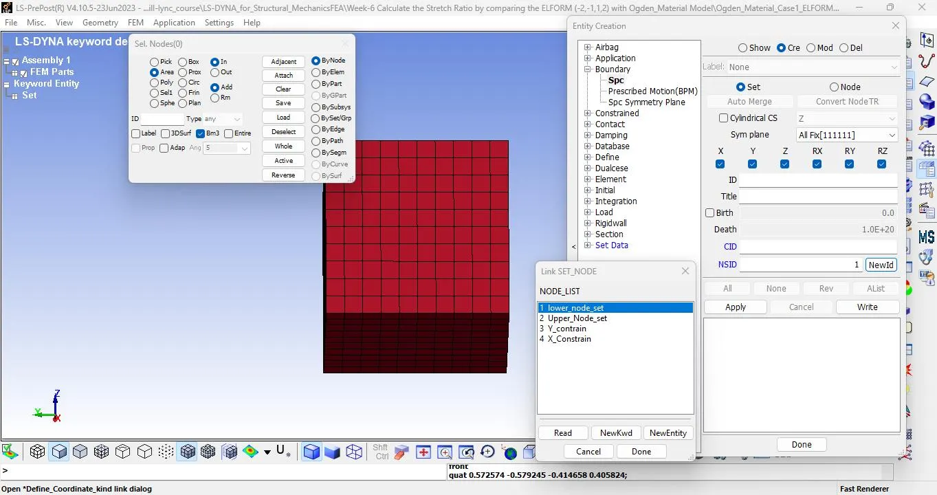
l Select node by area and select lower node set.
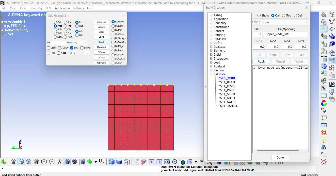
l Next select upper node set as per below image.
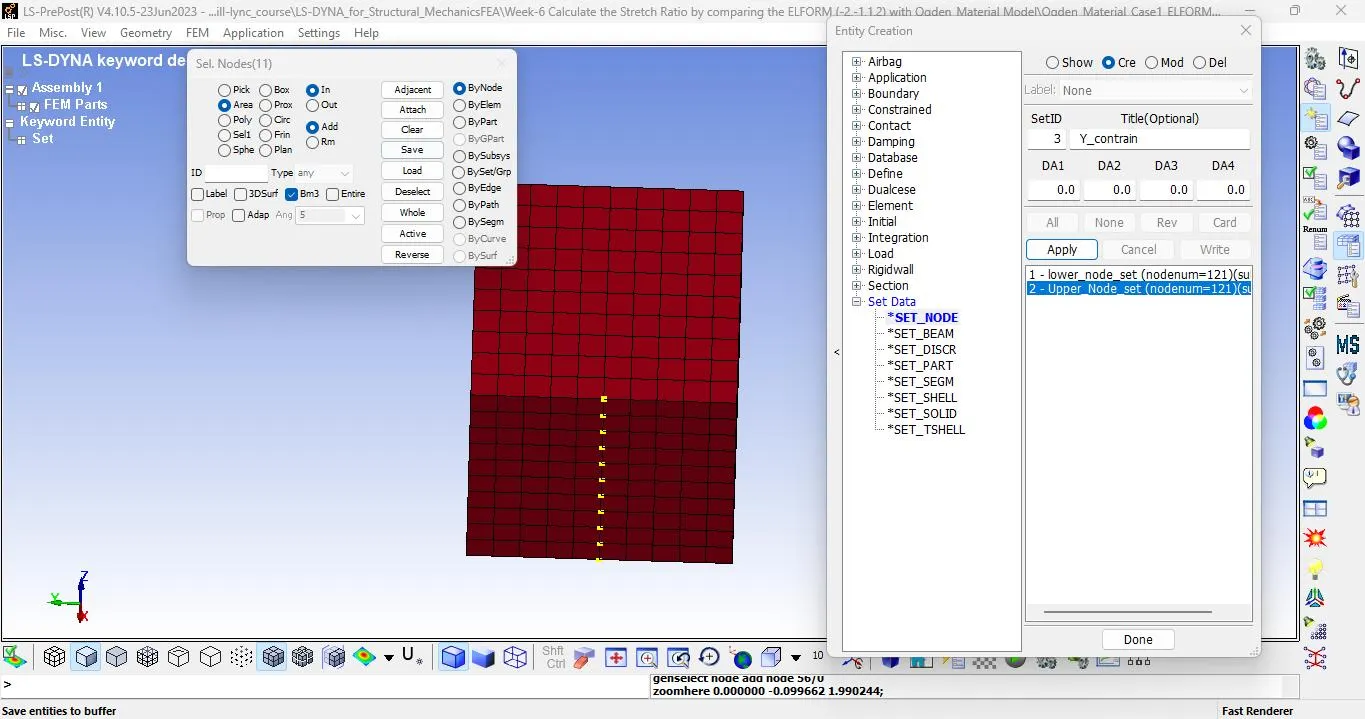
l Now select node as shown below (Y - Contrain).
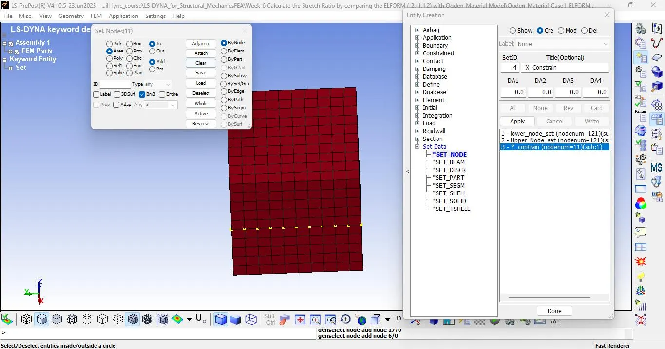
l Select node an horizontal axis (X - Contrain).
l Now create SPC. Go to model & part - create entity - boundary condition - SPC.
l Click create - set - in NSID - select LOWER NODE SET.
l Check z so that all lower node will constrained in z axis.
l Now select Y constrain node set.
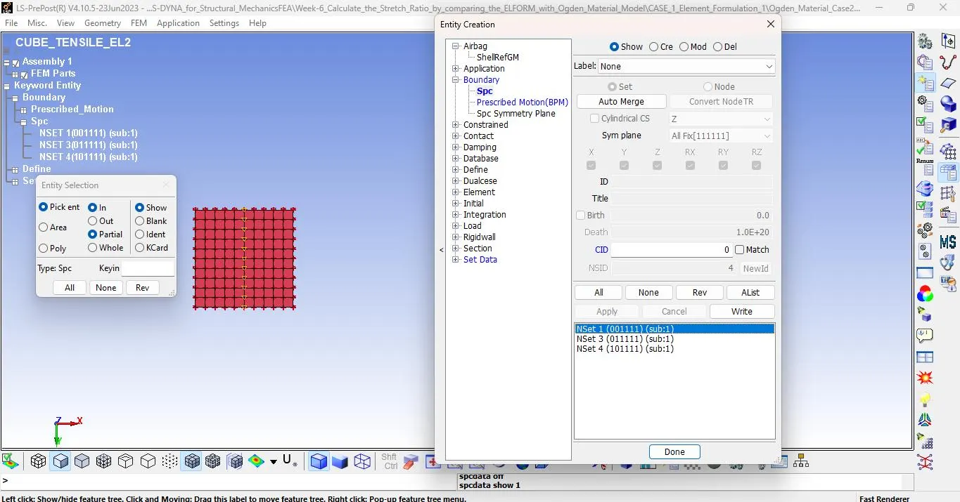
l Check on Y to fix the node in Y movement and after that select NSID : X CONSTRAIN.
l Check x box so that lower node it will not move in x axis also so that our cube will be fix at center.
l Now create prescribe motion set to the upper node .
l We know that stretch ratio is 5.
Stretch = 1 + Strain
5 = 1 + Change in length / original length
4 = Change in length / 10
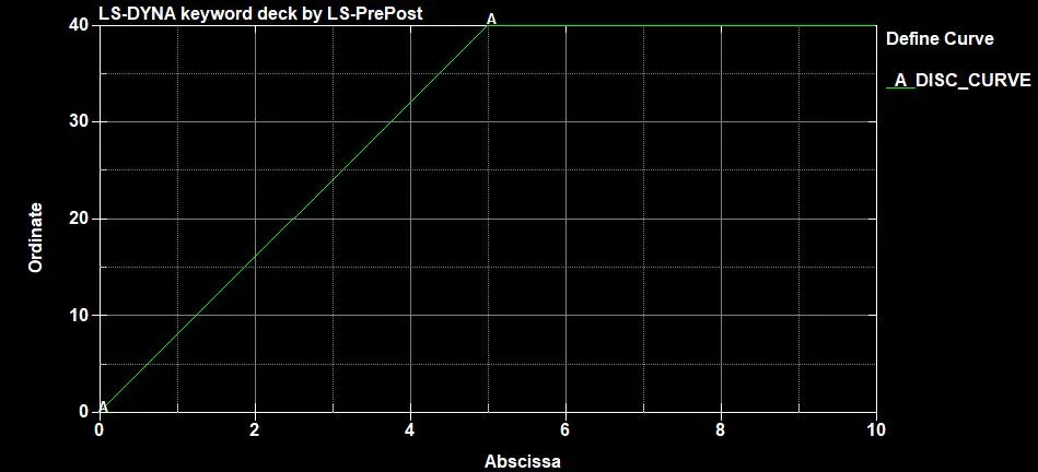
Change in length = 40
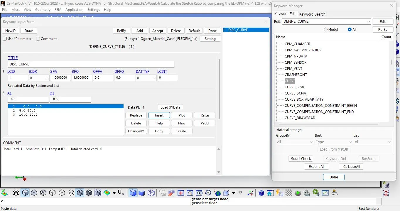
l We will create load curve for displacement upto 40 mm.
l Go to model & part - keyword manager - all - define - curve.
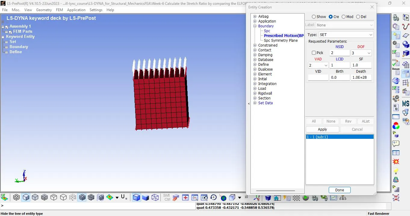
l Now define prescribe_Motion_set. Go to model and part >> create entity >> boundary >> Prescribe Motion.
l Select type - set & In NSID select upper node set.
l Enter DOF - 3 , VAD - 2, LCID - 1.
l Now we will define control card , here we will use implicit analysis as we know the time is 10 ms.
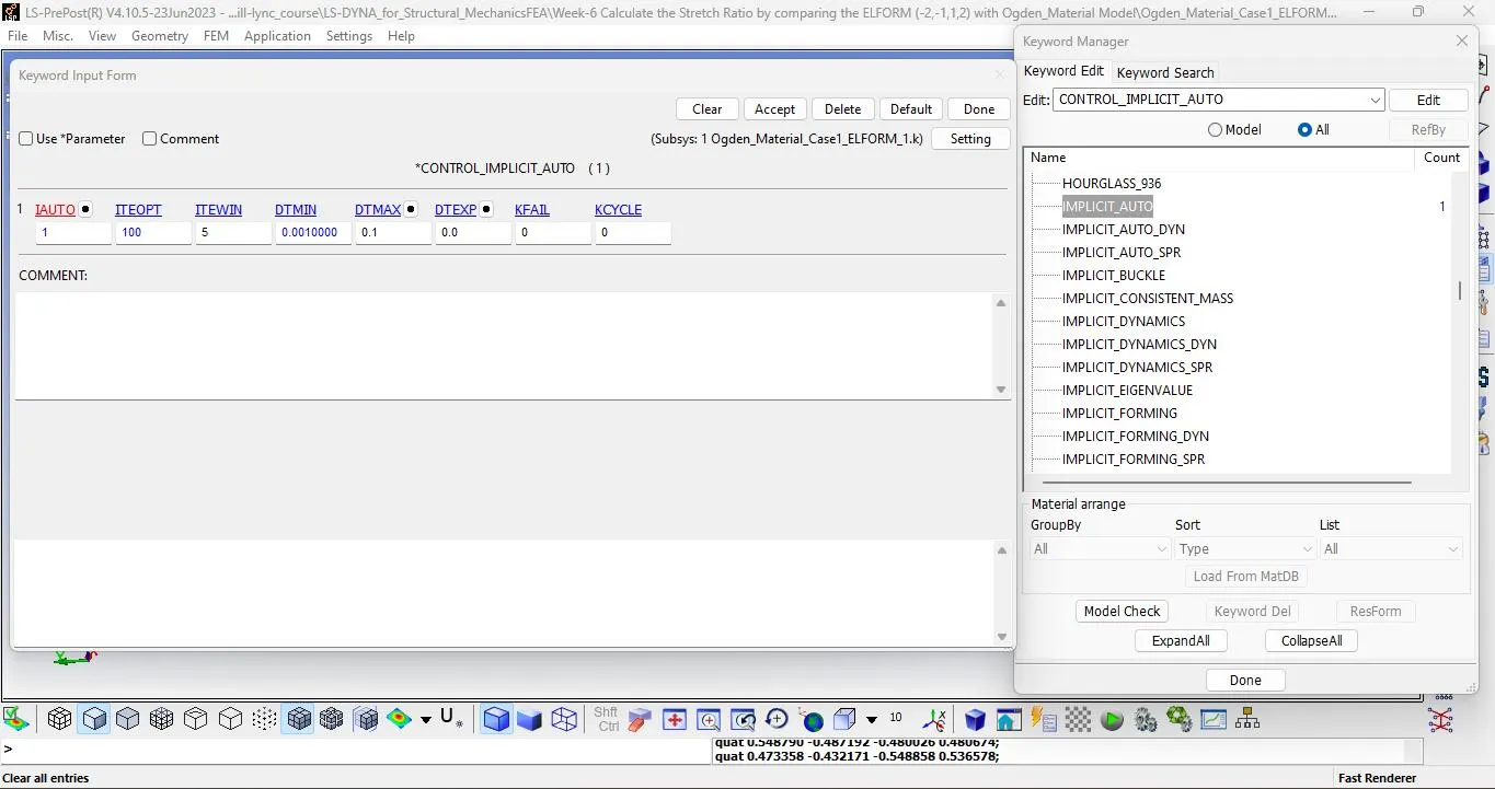
l Define Implicit cards. Go to Model and part >> keyword manager >> all >> control >> implicit_auto.
l Enter Automatic time step control flag : IAUTO : 1, ITEOPT: 100, ITEWIN: 5, DTMIN: 0.001, DTMAX: 0.1
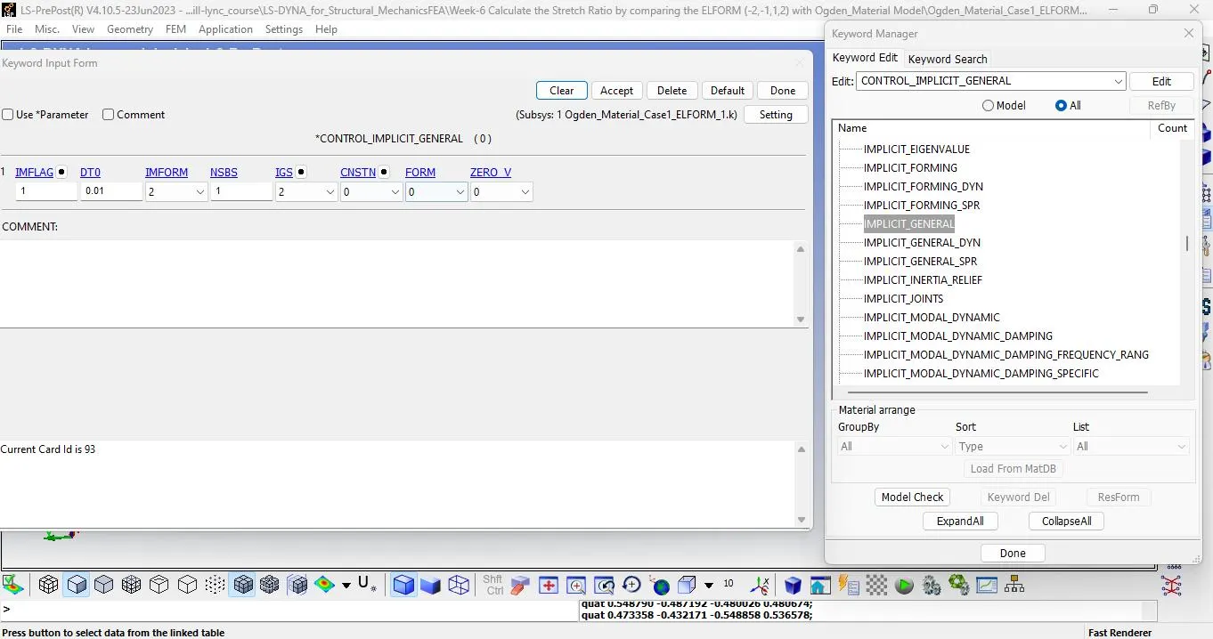
l Now define Implicit General card.
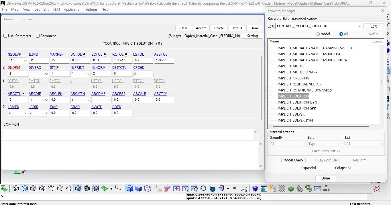
l Now implicit solution.
l Now define control termination card.
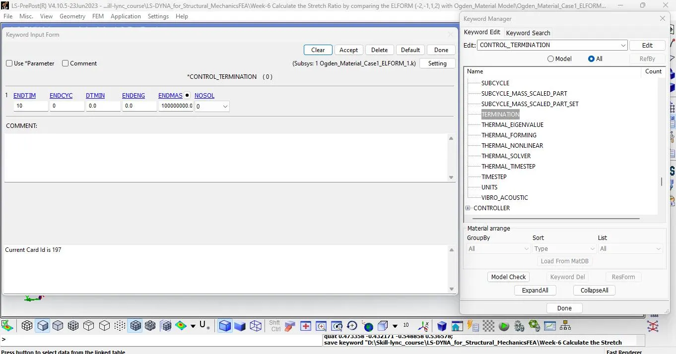
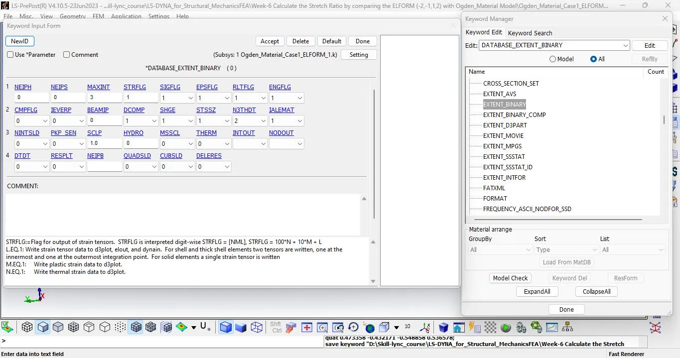
l Go to Model and part >> keyword manager >> all >> database >> extend_binary
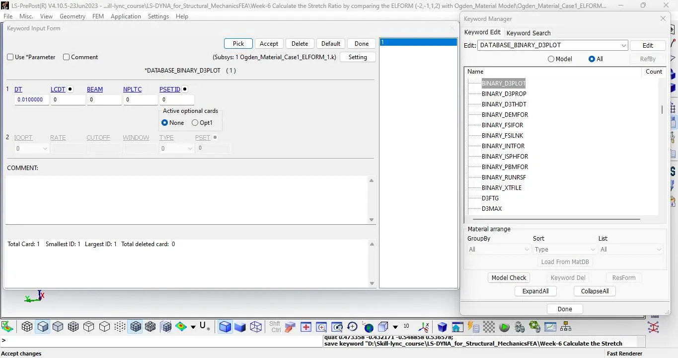
l Define Binary D3plot card.
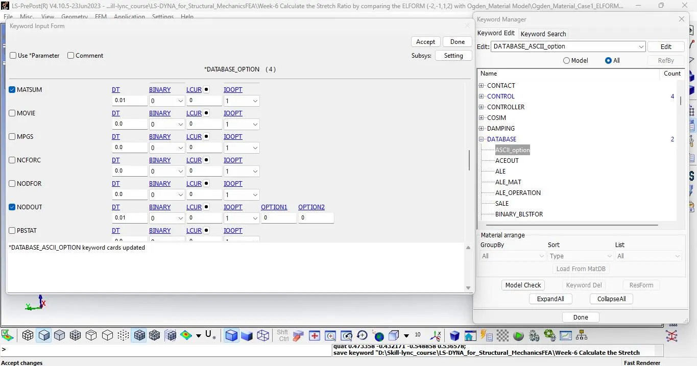
l Define ACSII_OPTION
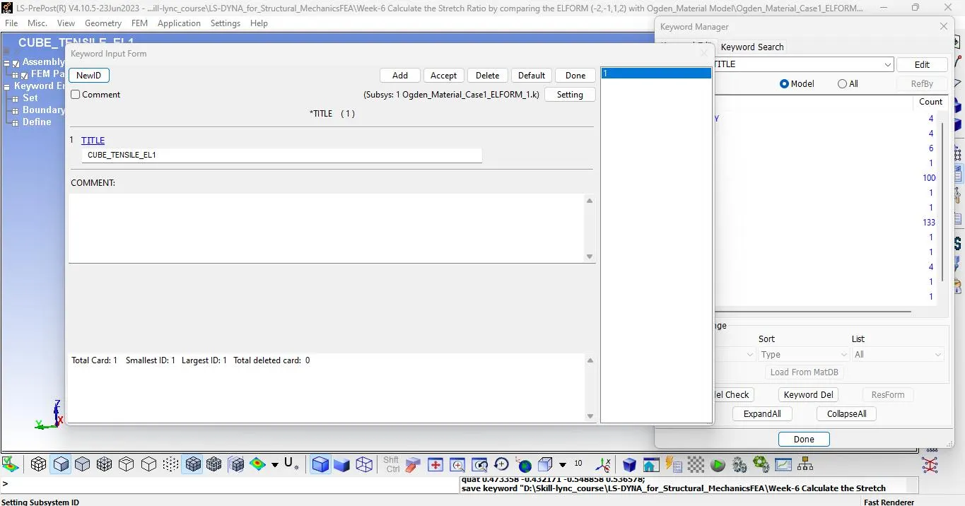
l Change the title from title card. Go to model - title - CUBE_TENSILE_EL1.
l Go to model checking >> Keyword check. Check for errors.
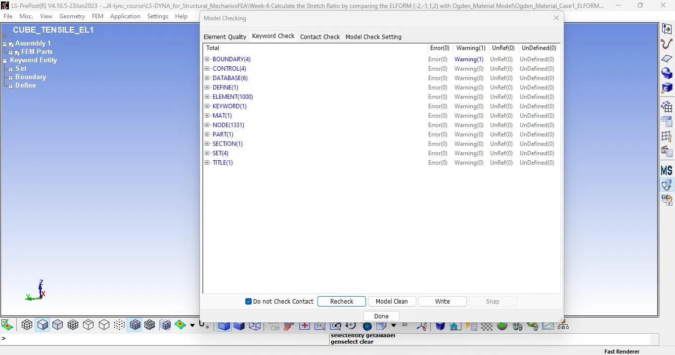
l We have zero keyword error and run the model.
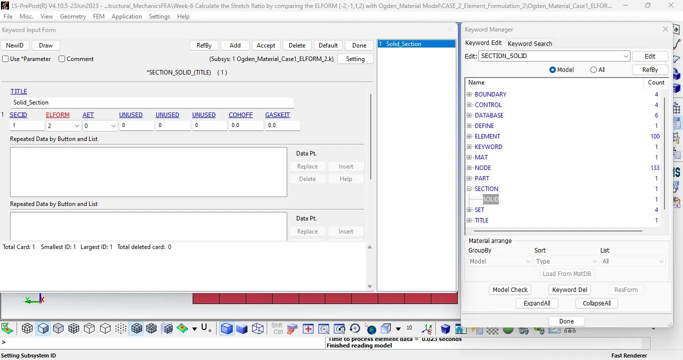
Ø CASE 2: ELEMENT FORMULATION (2)
l Follow the same setting and change the element formulation in section>> solid and run the model.
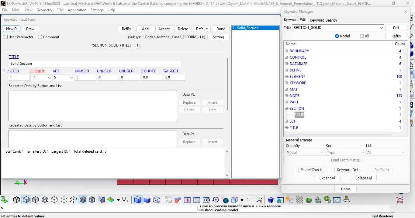
Ø CASE 3: ELEMENT FORMULATION (-1)
l Follow the same setting and change the element formulation in section>> solid and run the model.
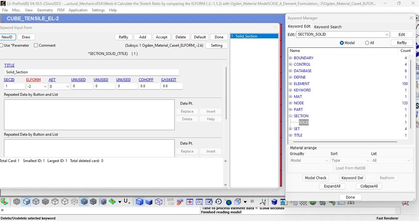
Ø CASE 4: ELEMENT FORMULATION (-2)
l Follow the same setting and change the element formulation in section>> solid and run the model.
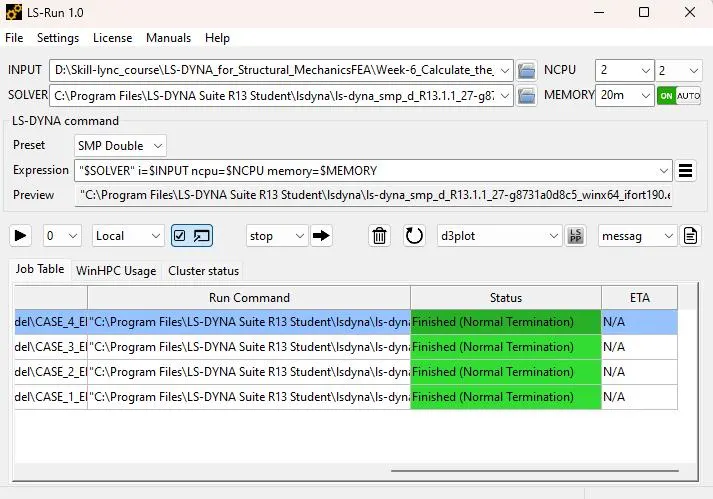
l After this we will run the model.
l Go to file - Run LS-Dyna and select the file and run.
RESULT:-
After running the simulation for different element formulations, the results will be as given below as per cases:
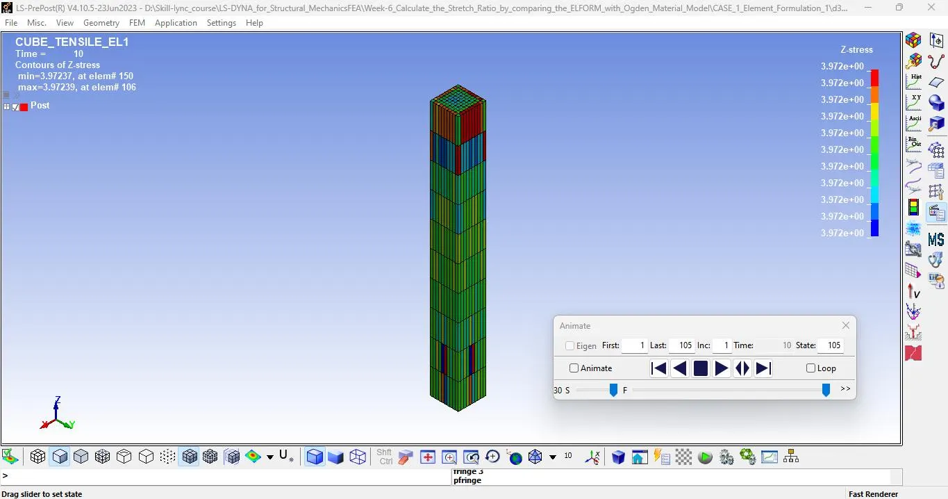
Ø Z - stress in case 1 : ELFORM 1
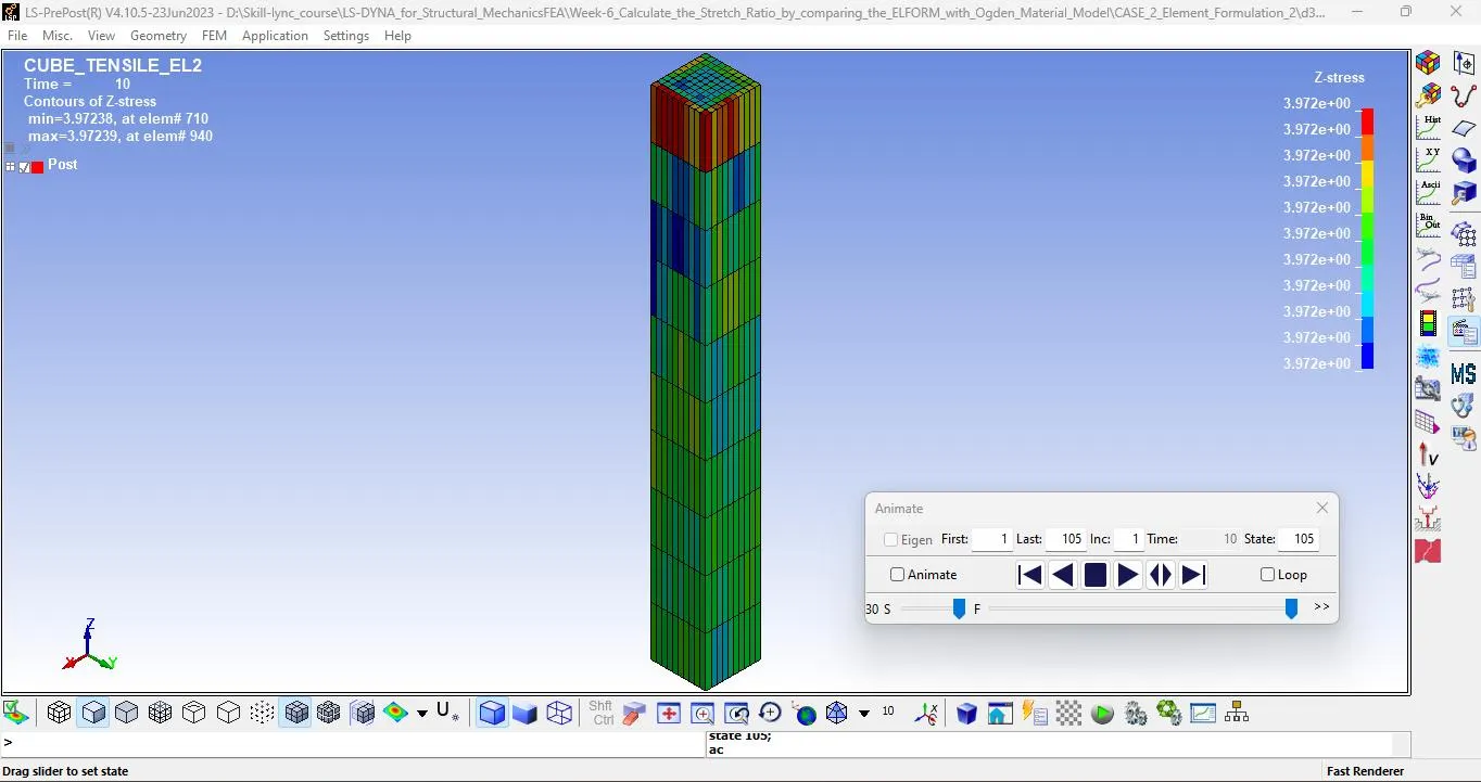
Ø Z - stress in case 2 : ELFORM 2
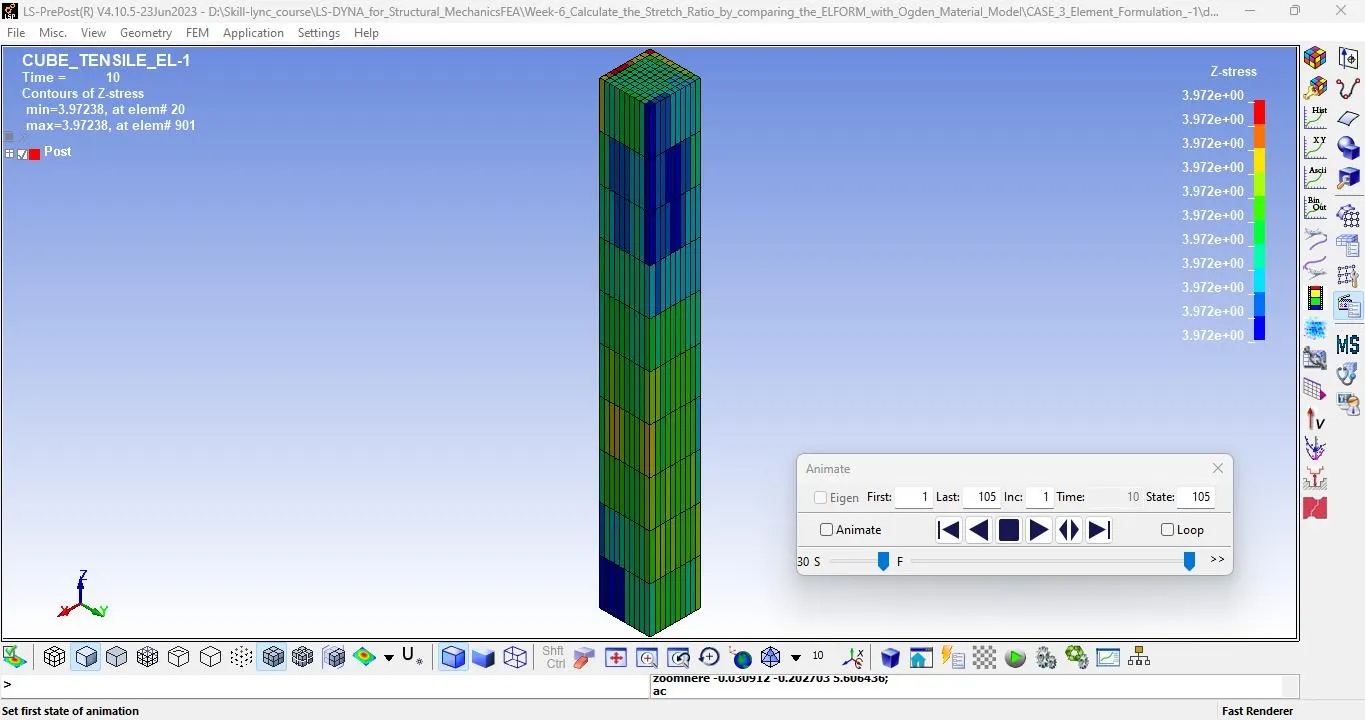
Ø Z - stress in case 3 : ELFORM -1
Ø Z - stress in case 4 : ELFORM -2
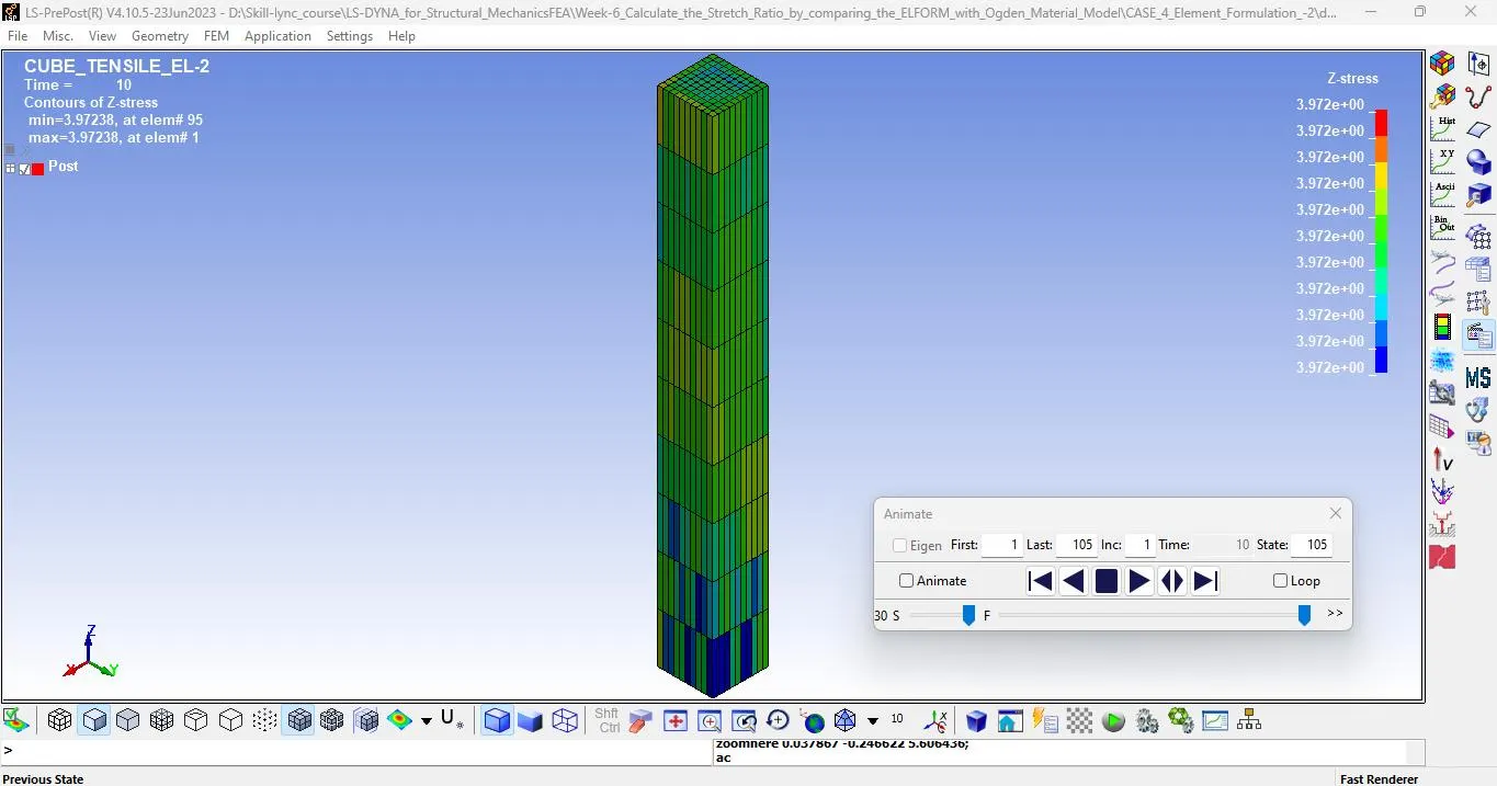
l We can see the stress results for different element formulations.
l Maximum stress we obtain is 4 Mpa along the Z-direction. As the tension is applied in Z-direction.
l We can observe the same value of maximum stress for all cases, but the distribution of stress is different in all cases.
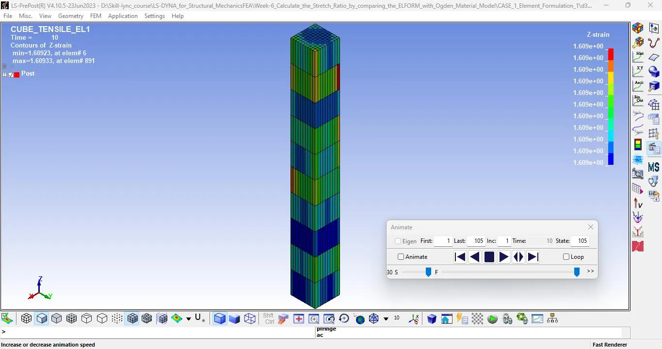
Ø Z - strain in case 1 : ELFORM 1
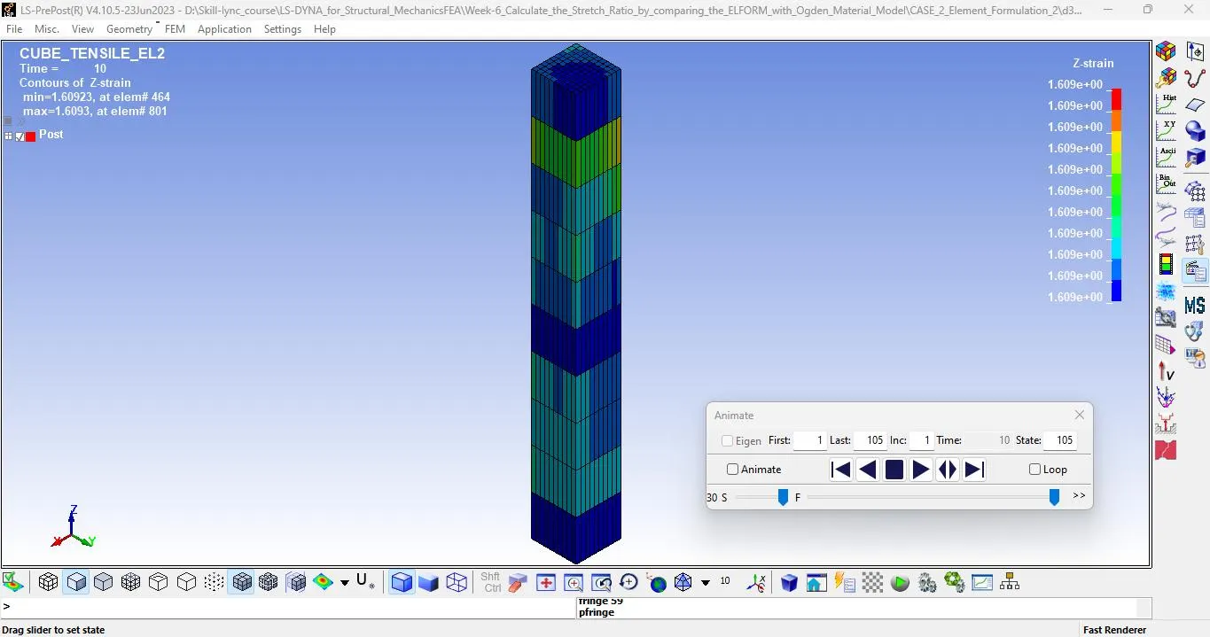
Ø Z - strain in case 2 : ELFORM 2
Ø Z - strain in case 3 : ELFORM -1
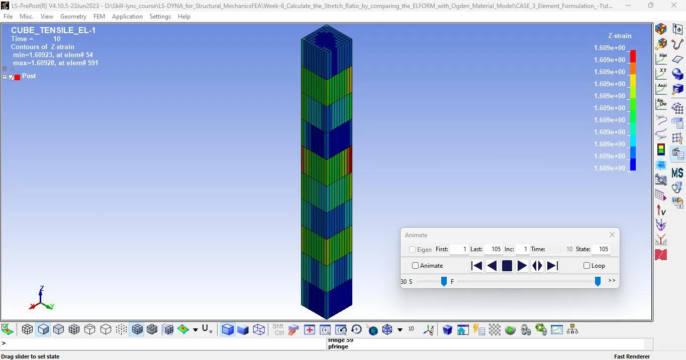
Ø Z - strain in case 3 : ELFORM -2
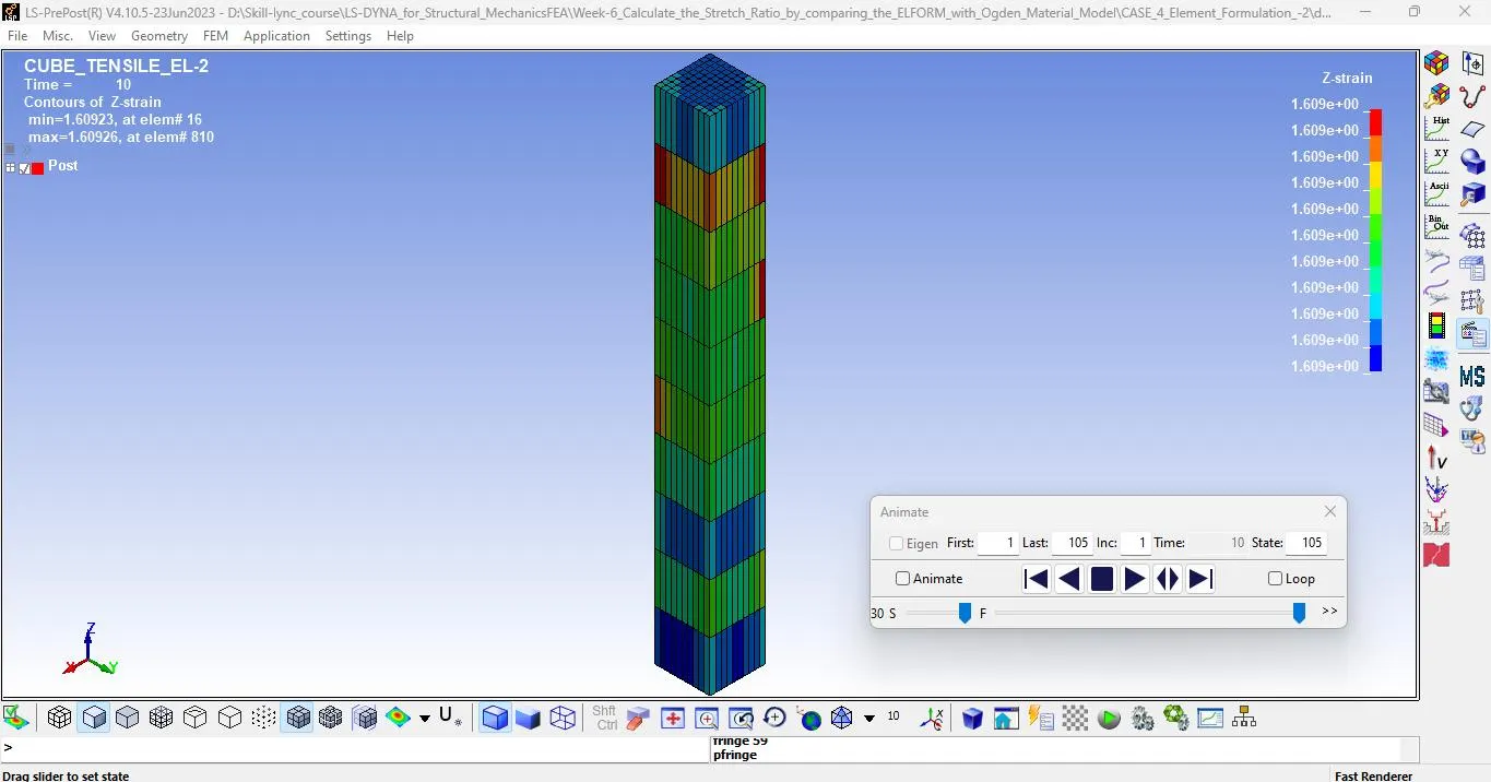
l Here also the maximum strain in Z-Direction is 1.60, which is same for all cases.
PLOTS:
Ø Stress plot in Z Axis at element 946 in case 01
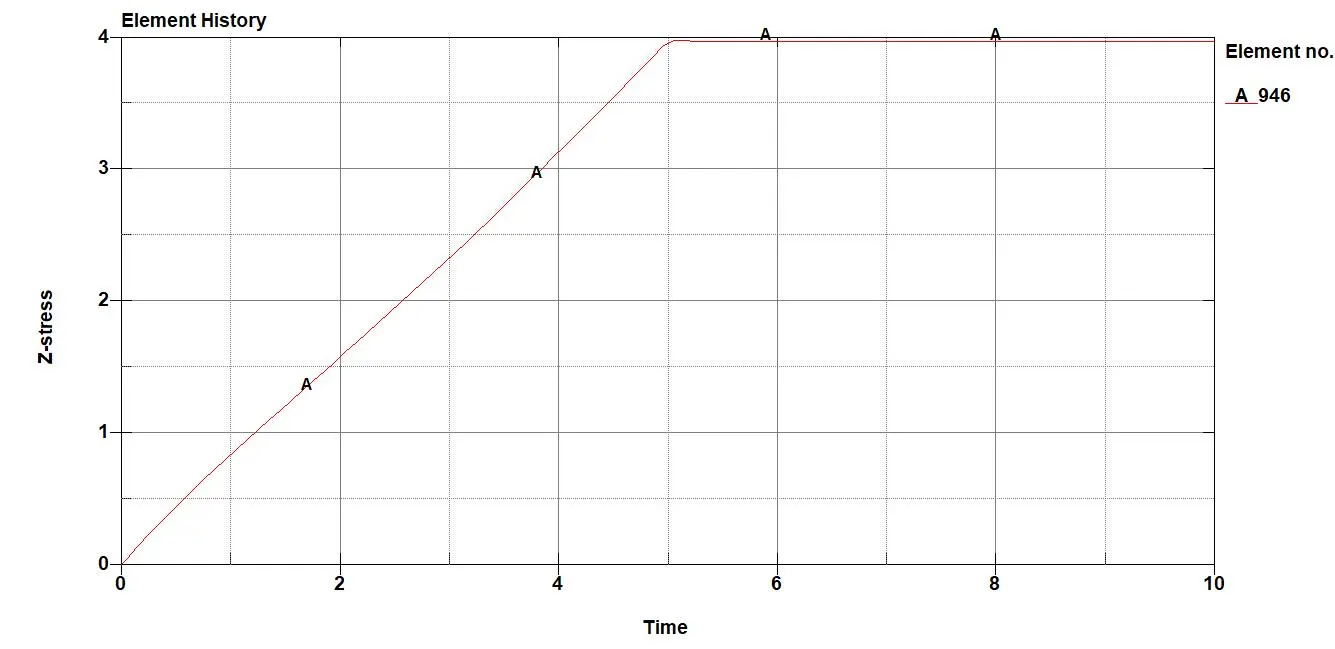
Ø Stress plot in Z Axis at element 946 in case 02
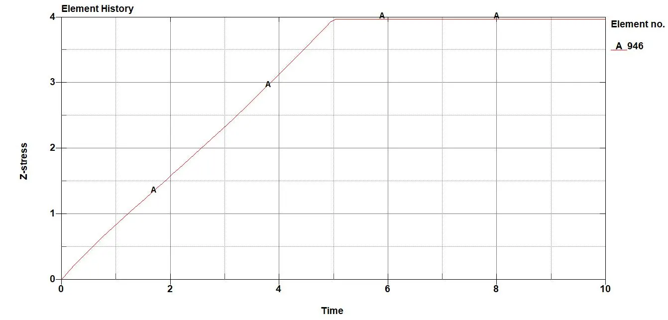
Ø Stress plot in Z Axis at element 946 in case 03
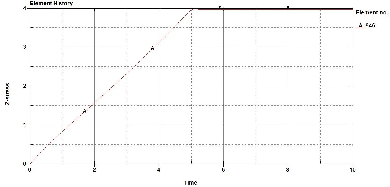
Ø Stress plot in Z Axis at element 946 in case 04
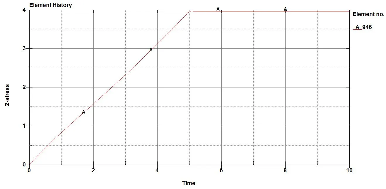
Ø Strain plot in Z Axis at element 946 in case 01
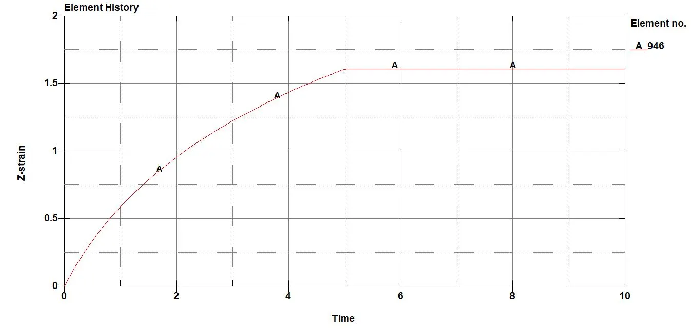 Ø Strain plot in Z Axis at element 946 in case 02
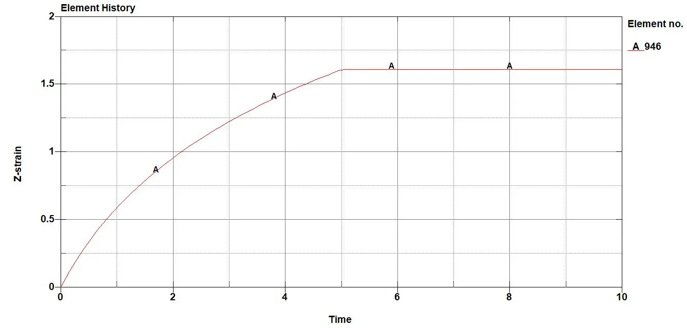
Ø Strain plot in Z Axis at element 946 in case 03
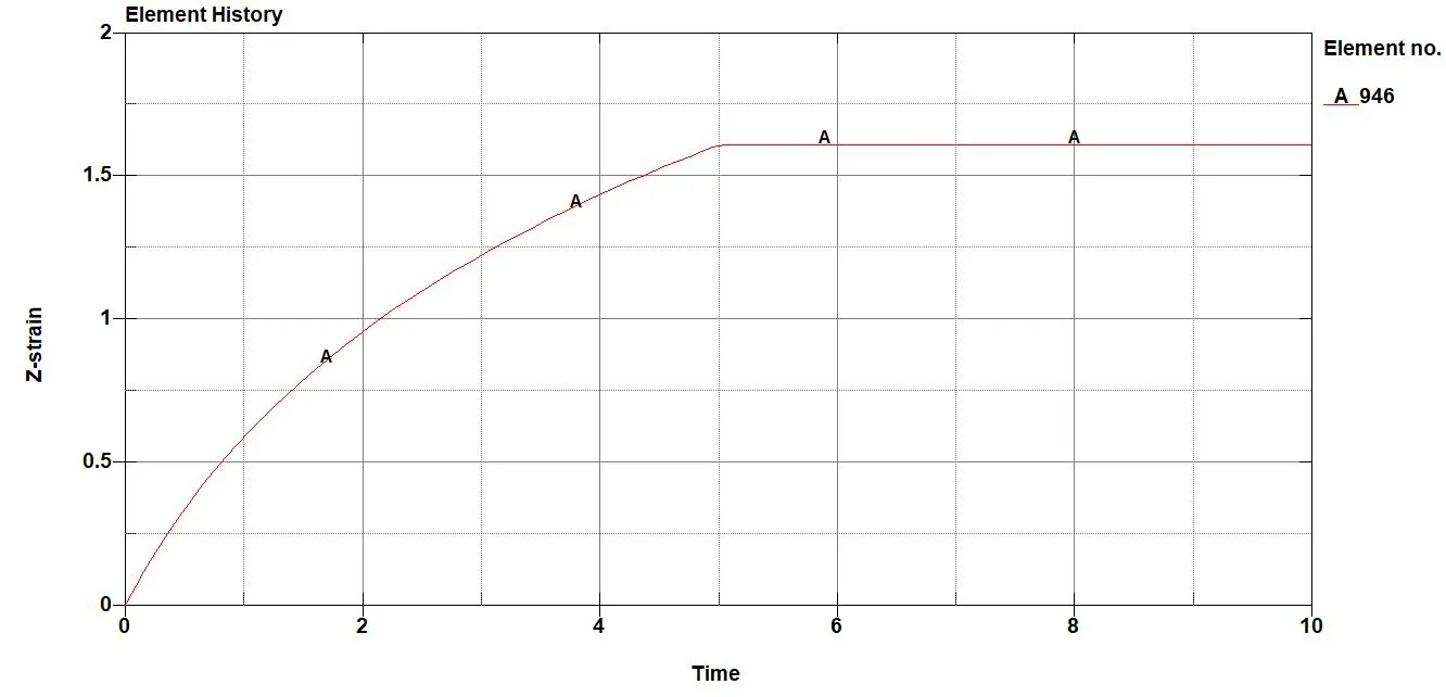
Ø Strain plot in Z Axis at element 946 in case 04
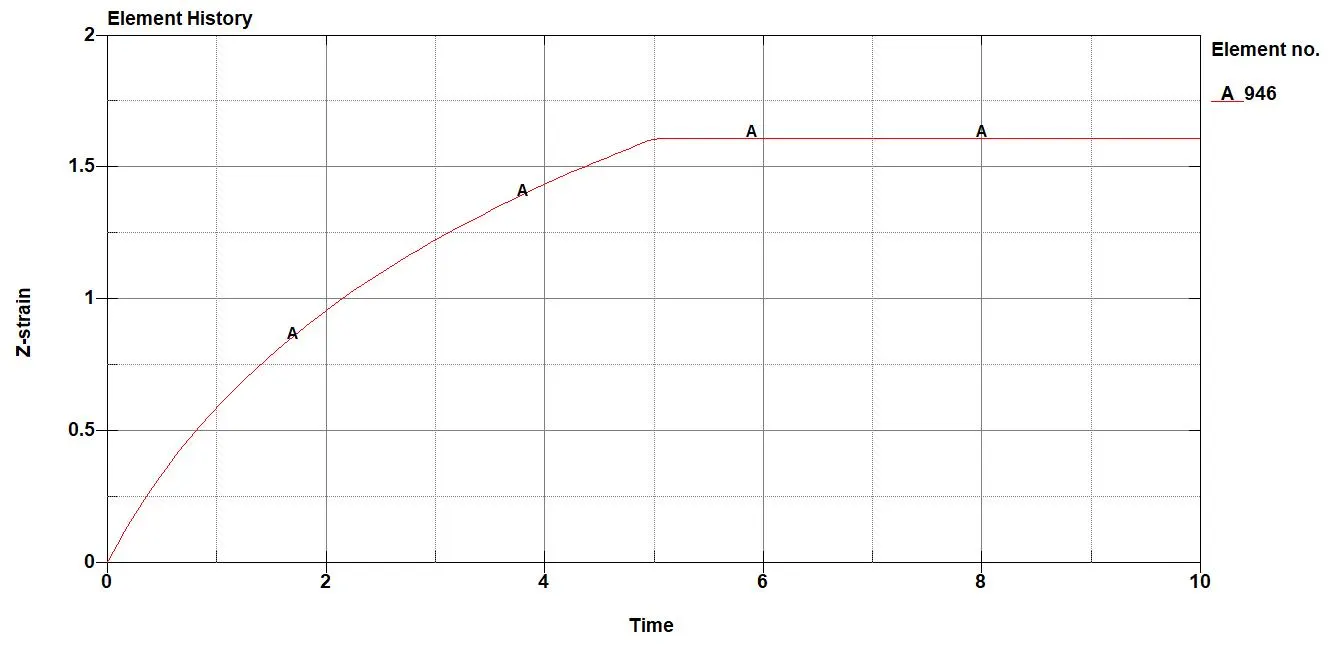
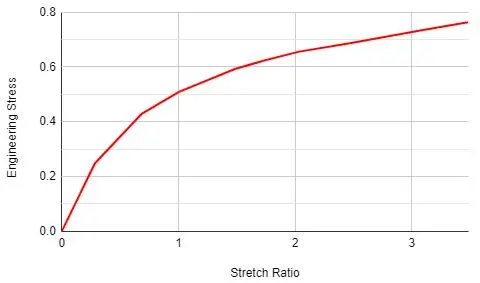
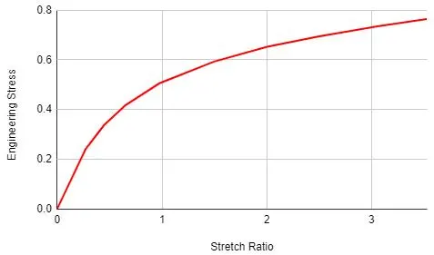
Plots of Nominal Stress Vs Stretch Ratio for Element formulation 1, 2,-1, and -2 as per case will be as given below:
Ø True Stress Vs True strain plot at element no 946 in case 1.
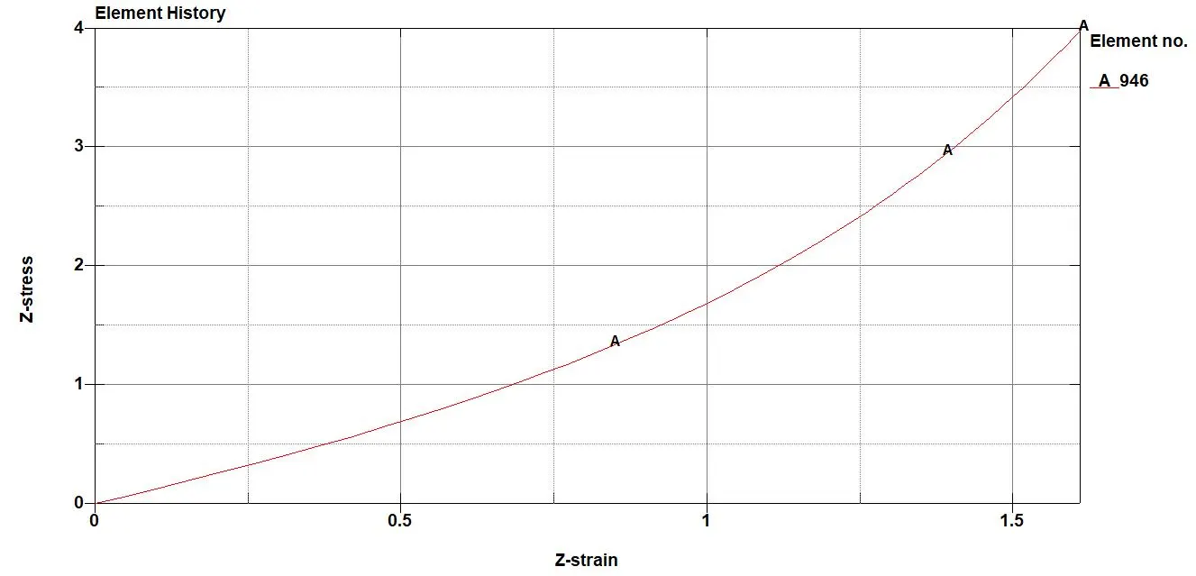
Ø True Stress Vs True strain plot at element no 946 in case 2.
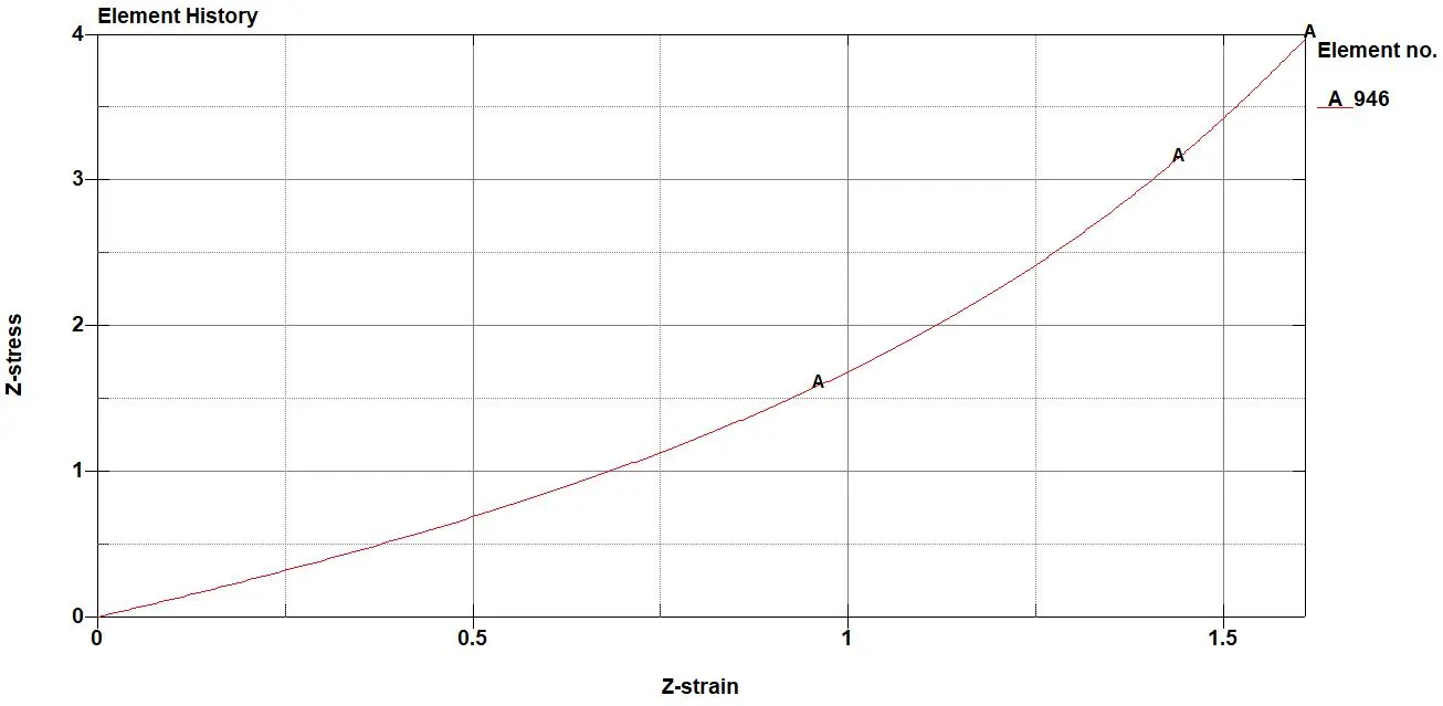
Ø True Stress Vs True strain plot at element no 946 in case 3.
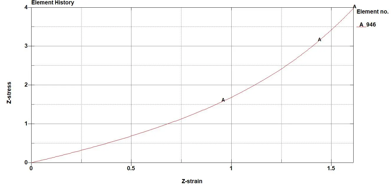
Ø True Stress Vs True strain plot at element no 946 in case 4.
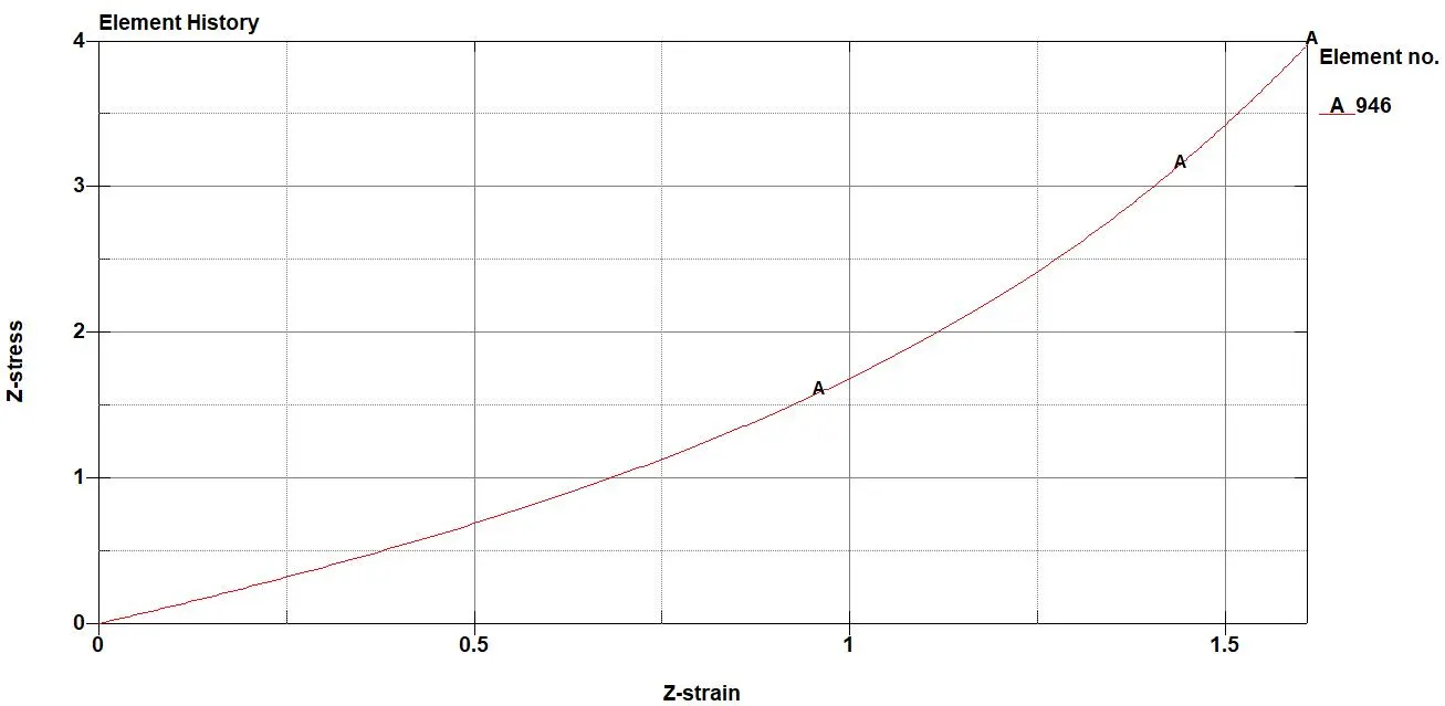
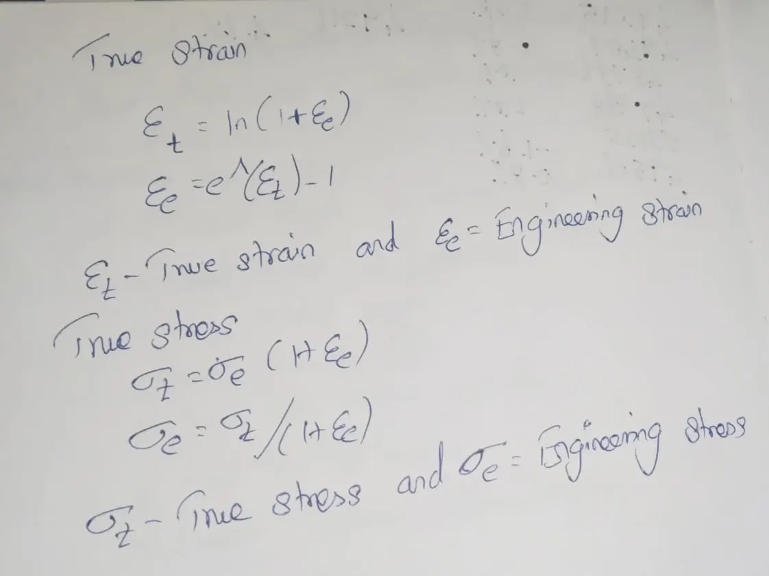
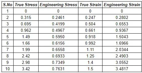
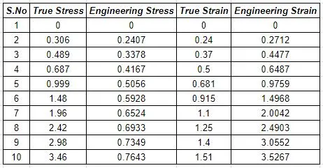
Now we will calculate the engineering strain and engineering stress with below formula.
we know that ,
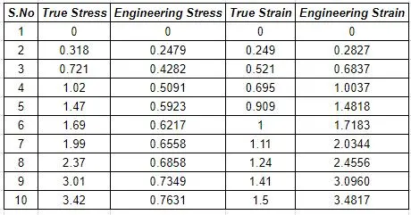
from above graphs, we have data of true stress and true strain, so that we had calculated engineering strain and engineering stress values as below
Ø CASE : 01 Element Formulation (1)
Ø CASE : 02 Element Formulation (2)
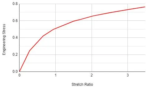
Ø CASE : 03 Element Formulation (-1)
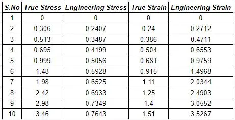
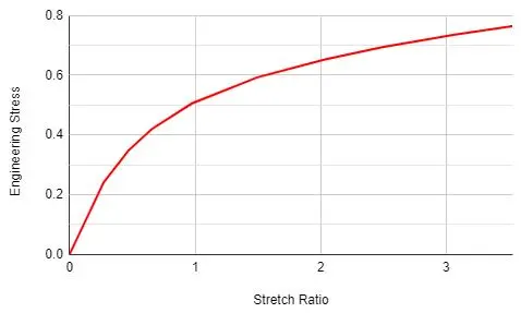
Ø CASE : 04 Element Formulation (-2)
CONCULSION:-
There is no much difference in values of stresses between the formulation for stretch of 5.
Usage of different element formulation depends on accuracy or efficiency (cpu time) requirements. In this case a large variation could not be found, when model is large enough we can notice a significant difference in the computation time.
NOTE: LS-DYNA FILE is too big to upload in website. So, I shared the google drive link to download.
Download link : https://drive.google.com/drive/folders/1_Qgtp42Zb5AosK8yAocWeXY7QBXfifXn?usp=drive_link