Week-6 Calculate the Stretch Ratio by comparing the ELFORM (-2,-1,1,2) with Ogden_Material Model.
Create a block of 10mmx10mmx10mm dimension with 10 elements for each direction and use the material card attached (Ogden_Material.k) that is representative of the material properties from the above figure.
Use appropriate boundary conditions to simulate tensile behavior for the model and finally compare the results from your simulation to the plot above up to stretch ratio 5. Only the uniaxial plot is to be compared.
Compare the results for the simulation using ELFORM = 1, 2, -1, -2
The unit of µ in the material definition is in MPa and α is a dimensionless quantity. Modify those quantities according to your unit systems.
Use a proper solver (Implicit/Explicit) and also explain the reason.
Hints:
- LS-DYNA the output of stress and strains from Post FringeComp Stress/Strain is given as true stress and strains.
- Stretch ratio l is defined as the ratio between the final length L and the initial length L0 of a component i.e. it is equal to (1 + engineering strain)
- Your boundary condition should be relatable with the real-time boundary condition.
- You need to add *Database_Extend_Binary card and activate the STRFLG to get the strain data.
Deliverables:
- An excel sheet with proper conversion and calculation of Stress/Strain and the Stretch Ratio for all the ELFORM.
- A proper image of the plot comparison of various ELFORMS against the Uniaxial Plot given in the challenge.
Submit a report explaining all the calculations and data from the simulation.
PS: This is a hyperelastic material model which will be covered in a later module. However, to work on this problem, knowledge of hyperelastic material is not required.
Implicit analysis for tensile test simulation:
Objective: To use study and understand implicit method and simulate tensile test on a rubber specimen comparing different material formulations and recreate the ‘stretch ratio to Normal stress’ relation as given in the plot.
Analysis Setup:
Implicit Analysis:
Used to perform linear static, quasi static simulations, where the simulation times and time steps are higher and the final answers/outputs are more important than their distribution over analysis time. It is preferred for simpler problems with small scale models as the analysis requires inversion of stiffness matrix, to calculate the (n+1)th state parameters which costs computational resource and time. Solution needs to reach convergence at each time step which makes it even more tedious.
In this simulation, a 10mm*10mm*10mm solid block with material properties of vulcanised rubber using Mat_Ogden_rubber(077_o) material card was subjected to a tensile test, till it reaches a stretch ratio of 5. The ultimate goal is to replicate the real life test data plot of such a test in the software and try to use different element formulations to get the most accurate results.
Stretch ratio as mentioned above is the ratio between the final length L and the initial length L0 of a component i.e. it is equal to (1 + engineering strain). The output we get from the analysis is the true stress and true strain, which needs to be converted into engineering stress and strain first to het the relation. As we know:
true strain ‘et’ = dl/ln and engineering strain ‘ee’ = dl/l0,
where ‘ln’ is the intermediate length in the previous time step, and ‘l0’ is the initial or original length of the specimen and ‘dl’ is the deformation.
The logarithmic strain is obtained by integrating this incremental strain,
∫δe=∫δl/l over L to l.
et=ln(ee+1)
Hence,
l0 = dl + ln ,
et = ln(1+ee), therefore, ee = exp(et) -1
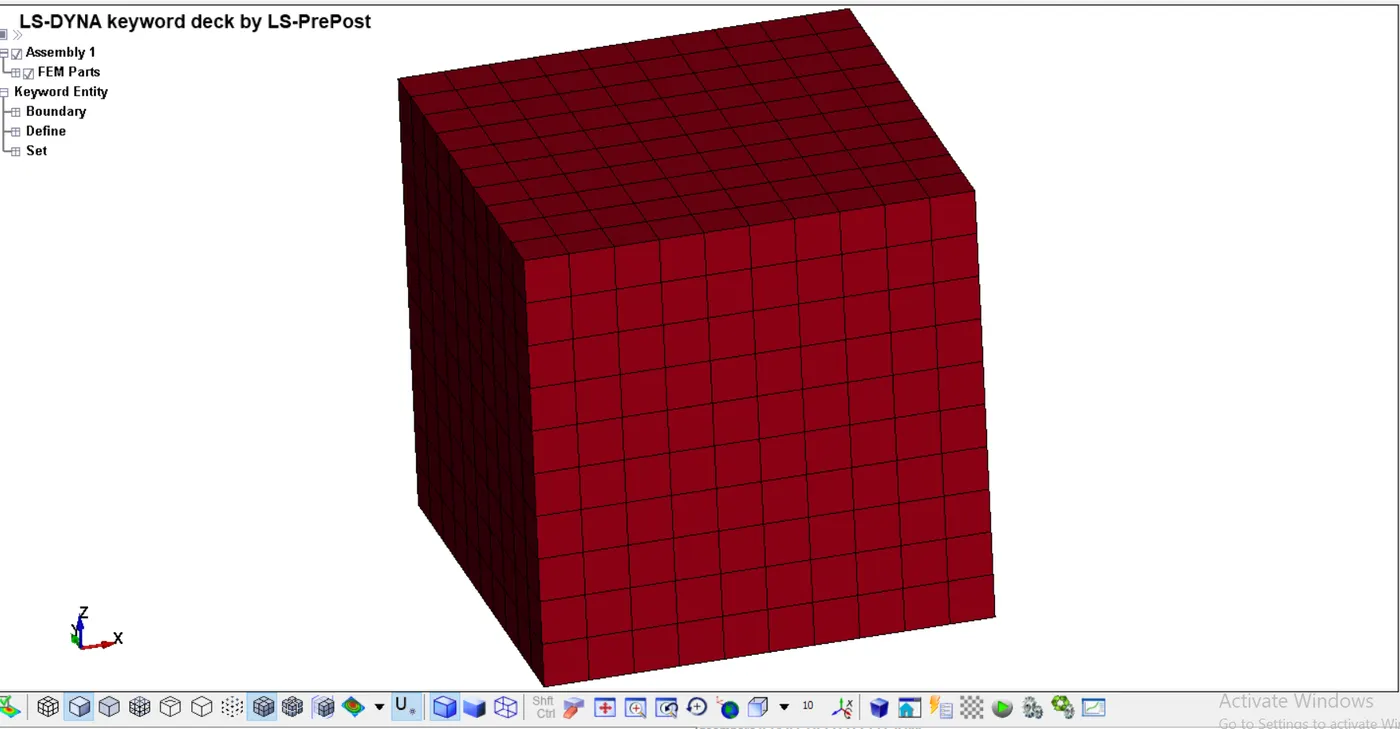
Using the ‘geometry’ option, a solid block with required dimensions was created, and was meshed using ‘solid mesh’ option with an element size of 1.
This part was then assigned the required material model, and a number of section cards were created and later assigned for each of the 4 cases.
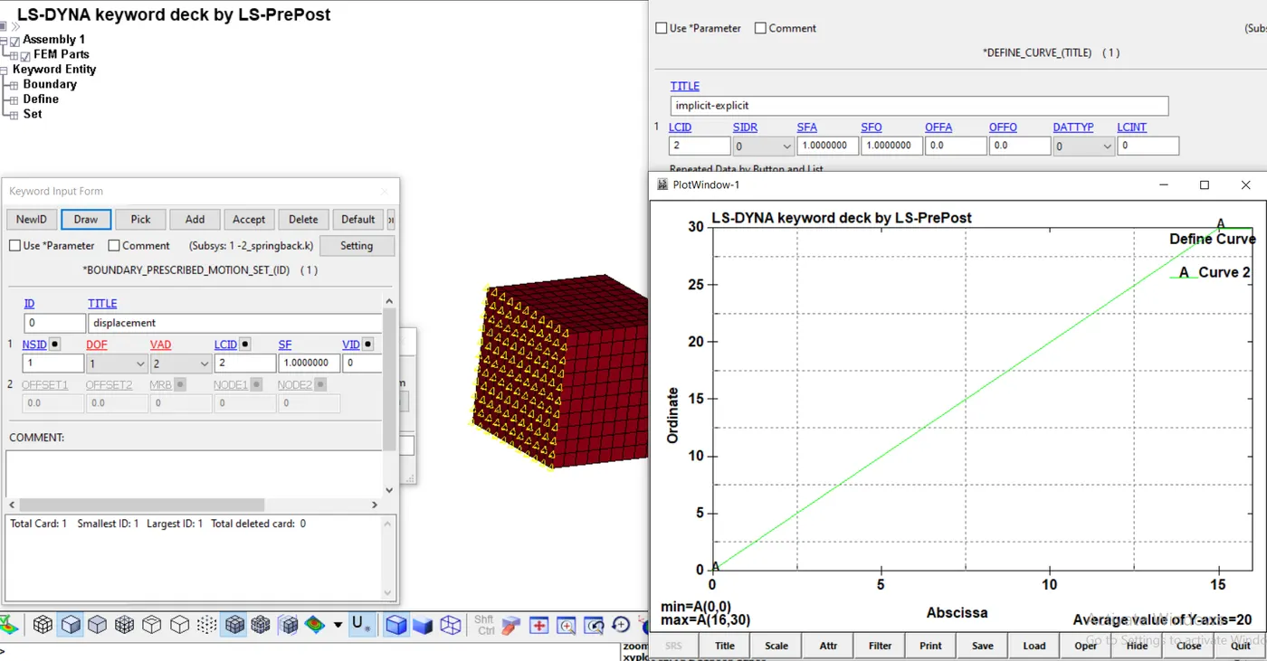
The loading is done using ‘prescribed_motion_set’ card in the ‘boundary’ keyword with the help of a linear curve of ‘displacement v/s time’ added in the ‘define’ card for the face heading in the ‘x’ direction by creating a set of all the nodes on it.
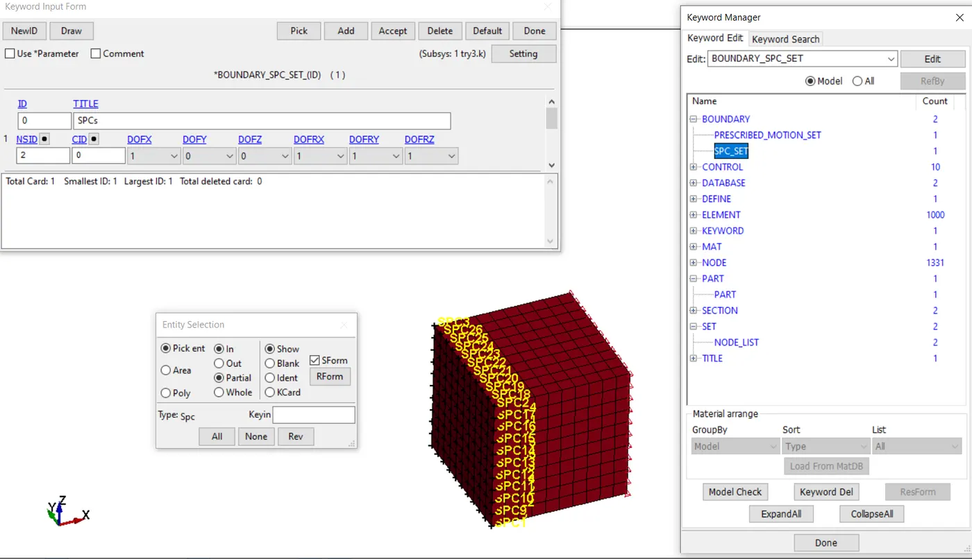
The opposite face was fixed using ‘spc’ card by creating another node set. The constraint was given only in the x-translation and rotation on all the other axes. The simulation was done for 100ms to keep the time steps a bit large with minimal iterations to get considerable accuracy for short time.
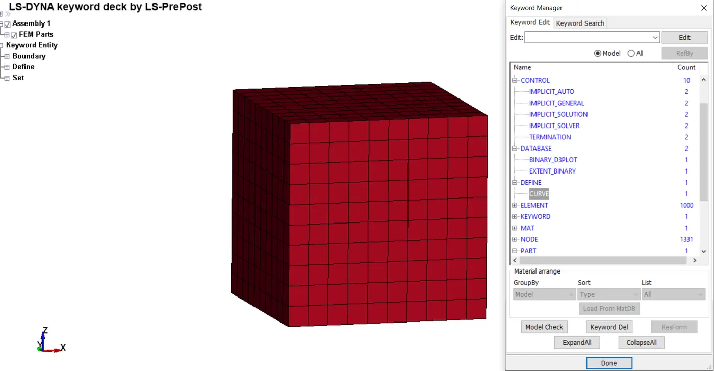
Using the implicit cards, the minimum time step, initial time step and the convergence criterion in terms of residual power was defined. The necessary output cards were defined as well and the analysis was commenced.
A [gm-mm-ms] unit system was used for the analysis, with a termination time of 100ms, with all the usual output cards to get the necessary data.
Procedure:
- PART, SECTION, MAT definition:
As mentioned earlier, using the geometry option the solid cube was created and the cards were assigned to it in the ‘part’ keyword.
The material card was given, and was assigned to the model. The card represents a hyper-elastic material generally used to represent rubbers, polymers etc.
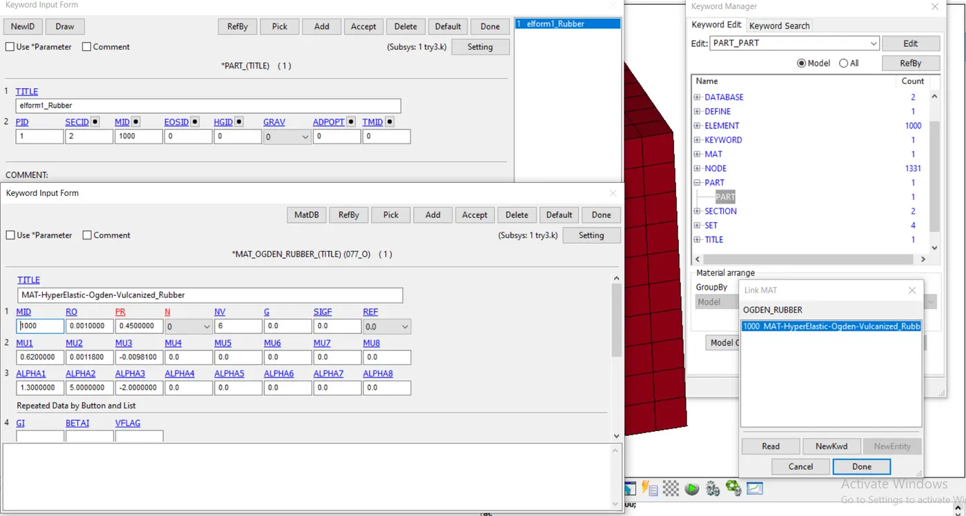
‘µ’s in the material definition are the shear moduli and ‘α’s are a dimensionless exponents.
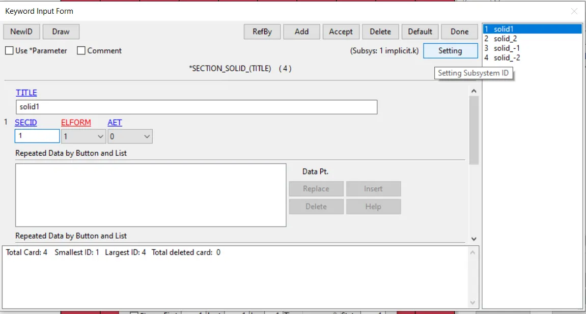
All the sections with their various element formulations were added in the keyword and then were assigned one by one for each of the case.
ELFORM -2 : fully integrated S/R solid intended for elements with poor aspect ratio, accurate formulation.
ELFORM -1 : fully integrated S/R solid intended for elements with poor aspect ratio, efficient formulation.
ELFORM 1 : constant stress solid element.
ELFORM 2 : fully integrated S/R solid.
- Boundary conditions:
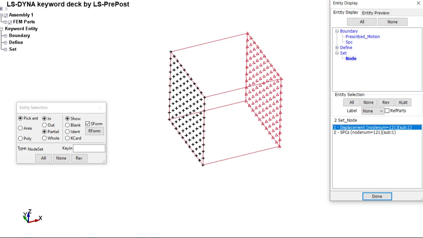
Prescribed motion was assigned to the face node set where the ‘displacement v/s time’ curve was called on.
The SPCs involved constraint in x-translational and all rotational degrees of freedom.
- Analysis setting:
As mentioned above, the necessary cards for an implicit analysis were added with default parameters for the ease of analysis.
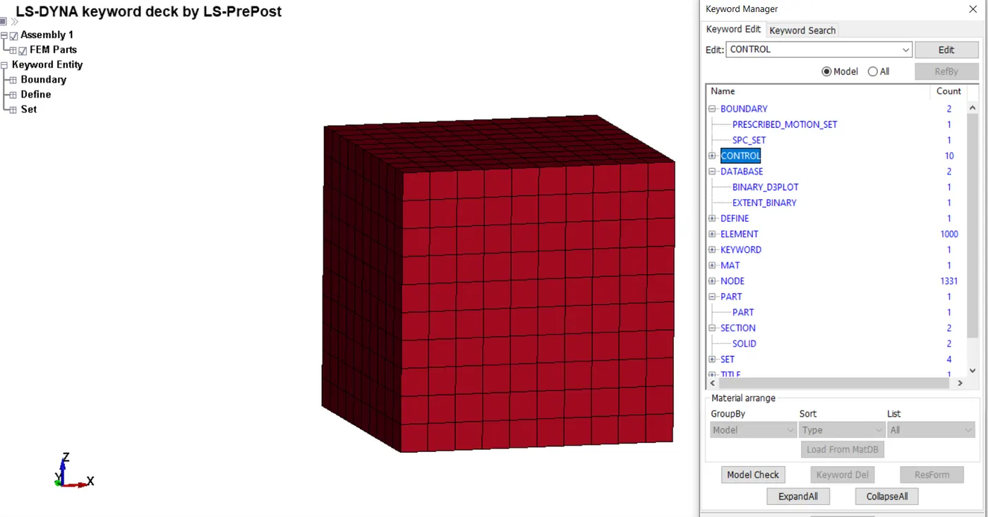
Just the ‘d3’ plot was requested in the output along with the strain data in ‘extend binary’ keyword.
Results:
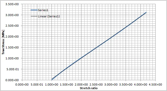
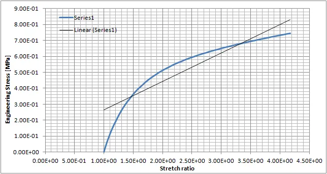
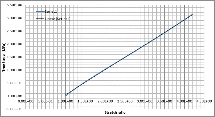
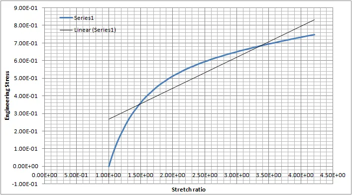
The analysis started going into numerical instabilities, with unfulfilled boundary condition after the stretch ratio reaches 3. However, the plot shows similar nature to the test data plot.
A simpler boundary condition where the constrained face has zero degrees of freedom had no issues and ther results are as follows:
Case 1: Elform = 1: constant stress solid element.
Stretch ratio v/s true stress:
Stretch ratio v/s Engineering stress:
Case 2: Elform = 2: fully integrated S/R solid:
Stretch ratio v/s true stress:
Stretch ratio v/s Engineering stress:
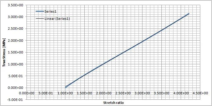
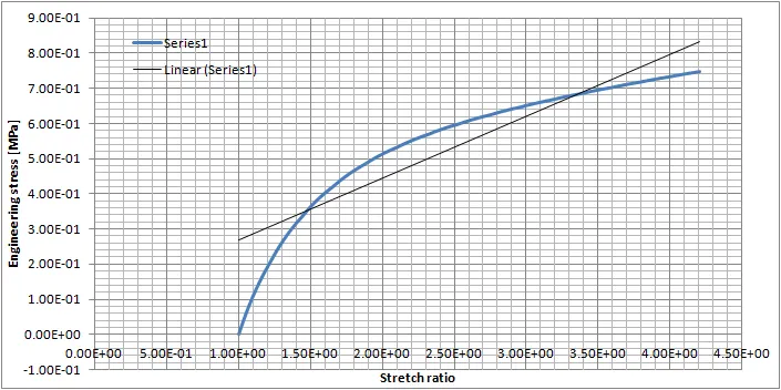
Case 3: Elform = - 1: fully integrated S/R solid intended for elements with poor aspect ratio, efficient formulation
Stretch ratio v/s true stress:
Stretch ratio v/s Engineering stress:
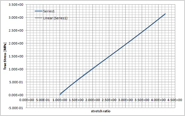
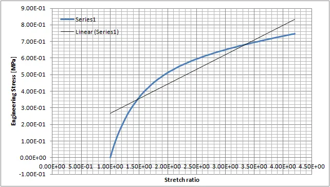
- Case 4: Elform = - 2: fully integrated S/R solid intended for elements with poor aspect ratio, accurate formulation
Stretch ratio v/s true stress:
Stretch ratio v/s Engineering stress:
Conclusion:
- Element formulations other than ‘Elform = 1’ involve detailed representation of the solid element and more integration points for better accuracy of results and more coherent distribution. This implies more calculation, more time and computation expenses as a result a bit better results are achieved which is not very clear in this case due to the lower resolution of mesh and non-linear nature of the analysis problem. On close observation it is evident that ‘Elform = - 2’ gives the best results.
- It can be concluded that implicit analysis is not suitable for non-linear problems as the accuracy of results doesn’t outweigh the time, and computation cost it requires, even in case of simpler examples. However, with more computation power, the analysis can be made efficient which is done in industry of certain problems.