Week-6 Calculate the Stretch Ratio by comparing the ELFORM (-2,-1,1,2) with Ogden_Material Model.
AIM:- To perform the uniaxial tensile behavior using the given material data and calculating the stretch ratio and comparing the ELFORM (-2,-1,1,2 ) by plotting engineering stress vs stretch ratio.
PROCEDURE:-
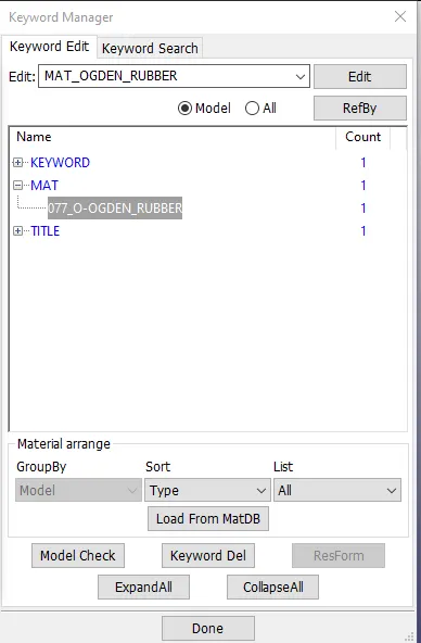
> We have to open the given file attached in the challenge by File > Open > Ogden_Material.k
> The file is containing only the material data.
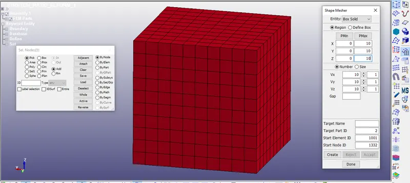
> As per the input information we have to create the 10mmx10mmx10mm block with 10 elements for each side direction.
> Go to Elements and Mesh > shape mesher > and create 10mm x 10mm x 10mm mesh block.
> Now we have to create the solid section with the different types of ELFORM ( -2,-1,1,2 ). Go to the Modal and Part > Keyword Manager > Section > SOLID. Assign the all data given below.
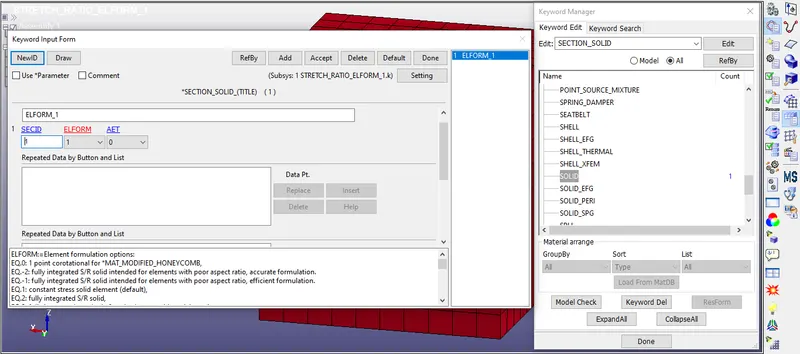
we have to Run 4 different cases;
Case 1:- ELFORM -2: fully integrated S/R solid intended for elements with poor aspect ratio, accurate formulation.
Case 2:- ELFORM -1: fully integrated S/R solid intended for elements with poor aspect ratio, efficient formulation.
Case 3:- ELFORM 1: constant stress solid element (default),
Case 4:- ELFORM 2: fully integrated S/R solid,
Material property ;
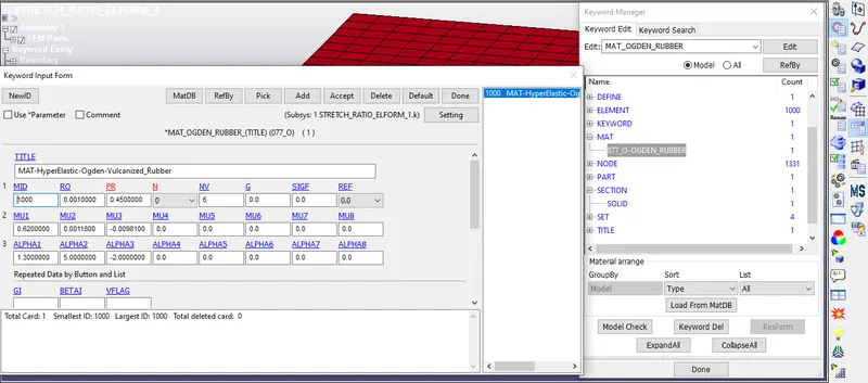
Now we have assigned the material and section to the part go to Model and Part > Keyword manager > part.
Assign the created section and material to the Part.
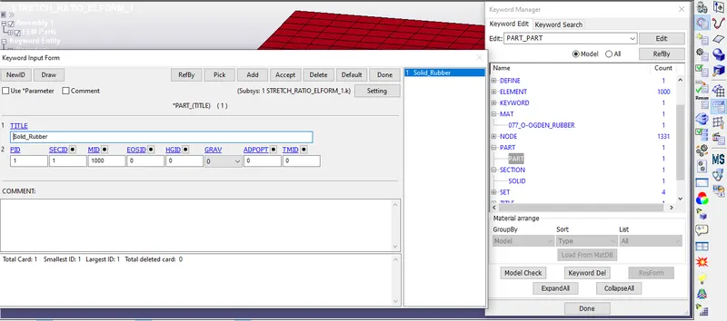
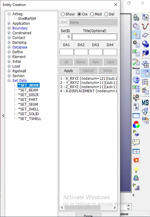
Now we have to create the boundary condition for that we are using the node-set.
For Node set go-to model and part > Entity creation. And then create the node-set.
Go to the Model and part > Keyword manager > BOUNDARY_SPC_SET.
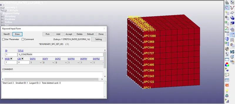
Give the constrain to the translation X direction and XYZ Rotational.
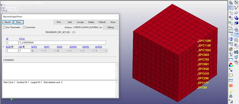
Give the constrain to the translation Y direction and XYZ Rotational.
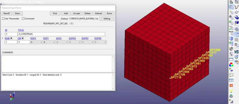
Give the constrain to the translation Z direction and XYZ Rotational
> Now we have stretching ratio 5 and we can calculate the displacement by below equation;
Engineering strian = `Ee = (deltaL)/L` ,
Stretch Ratio `lamda`= 1 + `Ee`
5 = 1 + `( deltaL)/10`
40 = `delta L`
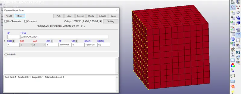
So we have to give the displacement to the moving surface.
> Now we have to define the load curve Go the model and part > keyword manager > Define > Curve.
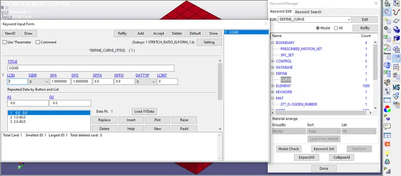
Now we have to assign this load curve to the moving node. Go to the modal and part > Keyword manager > BOUNDARY_PRESCRIBED_MOTION_SET
Now we have to assign the control cards,
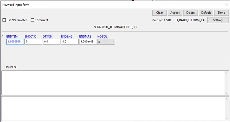
CONTROL_TERMINATION:- ENDTIM =1.0 which is the run time this is not the actual run time but for implicit analysis software count is the load step.
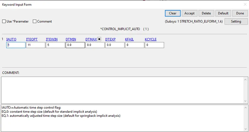
CONTROL_IMPLICIT_AUT0:- IAUTO = 1 which adjusts the time step for the implicit.
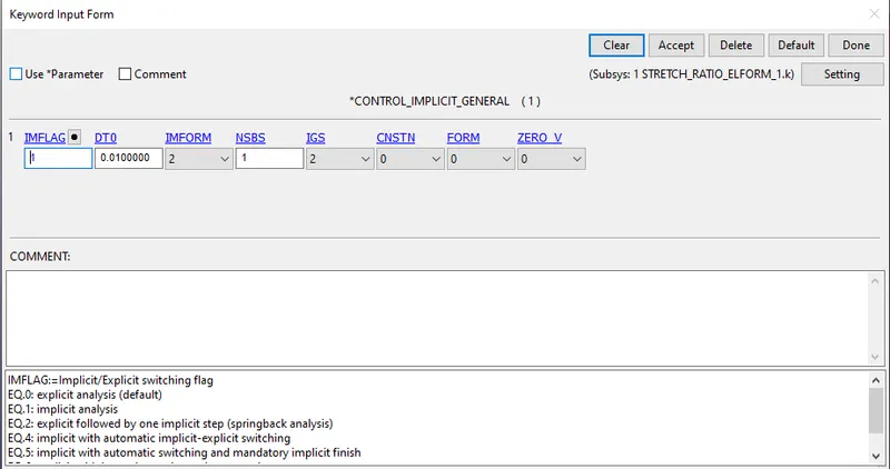
CONTROL_IPMLICIT_GENERAL:- IMFLAG =1 Active the implicit analysis.
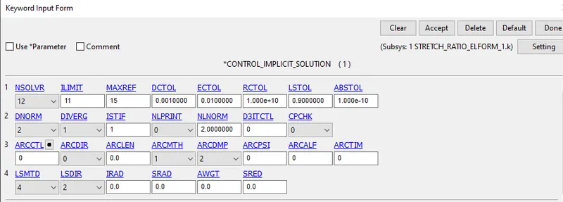
CONTROL_IMPLICIT_SOLUTION:- Which decides the linear or non-linear solution is performing.
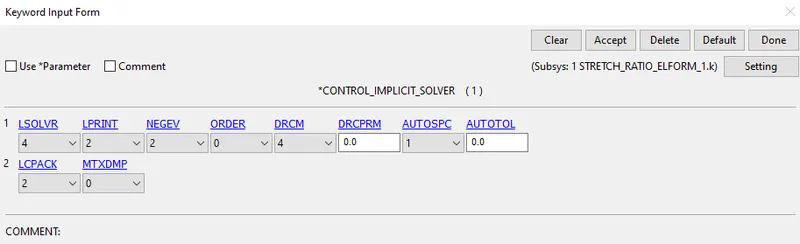
CONTROL_IMPLICIT_SOLVER:- use for the implicit calculation
Now we have to give the output request. Go to Modal and part > keyword manager > DATABASE >
active the BINARY_D3PLOT and DATABASE_ASCII option for GLSAT and the ELOUT.
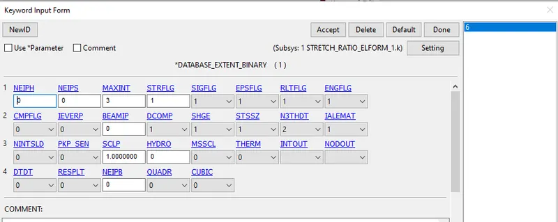
DATABASE_EXTENT_BINARY card with STRFLG=1 is used to calculate the elastic strain in the model.
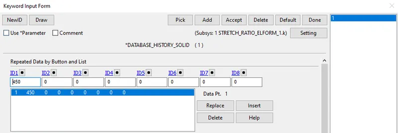
DATABASE_HISTORY_SOLID:- We give the element number 450 which computes the stress/strain.
Before submitting for the run we have to check the deck with the help of a model check.
now save the file and run the file in solver.
RESULTS:-
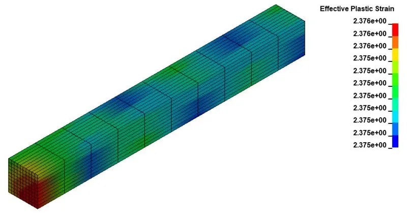
Effective Plastic Strain of ELFORM_-2
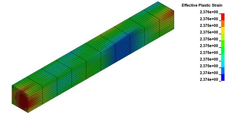
Effective Plastic Strain of ELFORM_-1
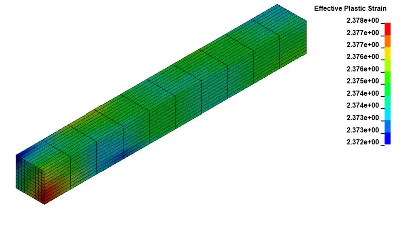
Effective Plastic Strain of ELFORM_1
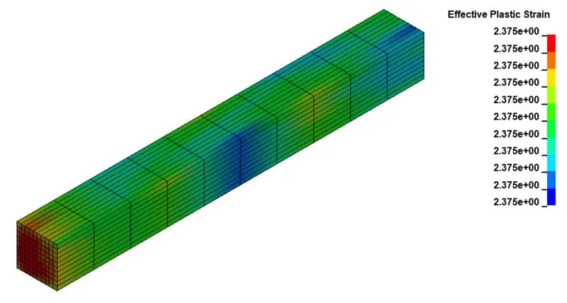
Effective Plastic Strain of ELFORM_2
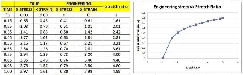
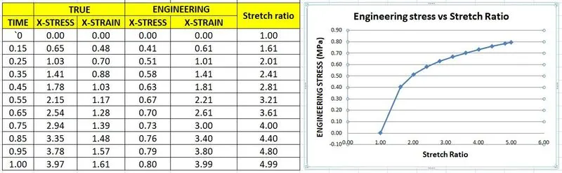
calculation of engineering stress/strain and stretch ratio.
after simulation, we got results that show the true stress/strain value and we have to convert it into engineering stress-strain by the following formula.
True stress , `sigma_t = sigma_e(1+epsilon_e)`
Engineering stress, `sigma_e=sigma_t/(1+epsilon_e)`
true strain, `epsilon_t=ln(1+epsilon_e)`
Engineering strain, `epsilon_e=e^(epsilon_t)-1`
stretch ratio, `lamda`=`1+epsilon_e`
ELFORM=-2
ELFORM=-1
ELFORM=1
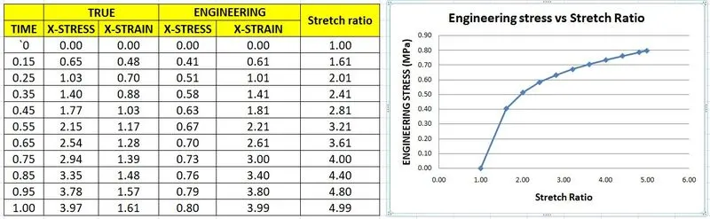
ELFORM=2
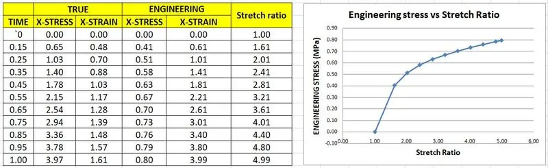
CONCLUSION:-
The uniaxial tension test was solved by using an Implicit solver. because the material we use is hyperelastic nonlinear material.
From the graph, we can see that the egg. stress vs stretch ratio graph are almost same and the stress in 0.5 MPa and when the stretch ratio is 5.
From the given graph of Ogden material, we can see that the stretch ratio 5 the stress is 1.8MPa due to the material nonlinearity of the material