Week-6 Calculate the Stretch Ratio by comparing the ELFORM (-2,-1,1,2) with Ogden_Material Model.
Understanding the stretch ratio of hyper-elastic material and plot the graph for all ELFORM (1, 2,-1,-2) using implicit / explicit solver by creating the block using given material card.
Objective :To perform simulation using a block to understand the behavior of hyper-elastic material using implicit/ explicit solver using Ogden material card using different ELFORM (1,2, -1,-2).
The Ogden material model is a hyper elastic material model used to describe the non-linear stress-strain behaviour of complex materials such as rubbers and biological tissue. The model relies on the fact that the material behavior can be described by means of a strain energy density function, whence the stress-strain relationships can be derived. The Ogden model is often used to model rubberlike materials such as polymers, and biological materials. These materials can generally be considered to be isotropic, incompressible and strain rate independent.
Model set-up: To create a model of given size for tensile test, first we need to create meshed model using mesh tool bar.
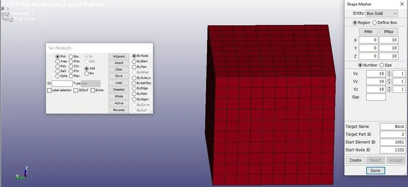
Mesh > Shape meshed > set the radio button in size > set the size as 10 in the three direction and set the step as 10 > create >>accept. We need to create the model using the *Include card.
Analysis: To understand the material behavior by performing the simple tensile test on the meshed model using the different ELFORM (1, 2,-1,-2) at section in the keyword manager.
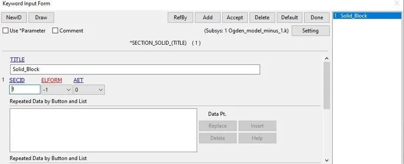
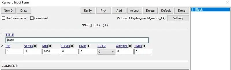
Section and Part Card: here we can change the ELFORM, we need to assign the section solid here then assigning the section Id and material ID in the part Card.
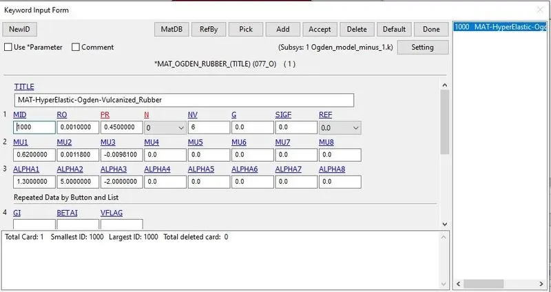
Material Card: the given material property is predefined card which is available here in the model.
Boundary conditions:
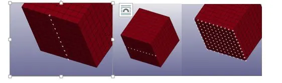
We need to constraint the elements to perform the tensile test for the fixing the elements any translation direction as we see in the below images, we have constrained the elements in translation Z-direction and rotational X, Y and Z.
To maintain the uniform stretch, we need to constrained the elements in vertical YZ- translation
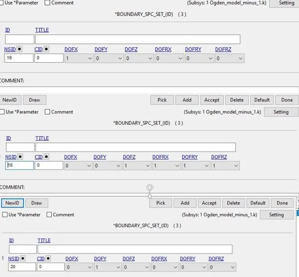
In below figure we can see the SPC details ,Constrained in translation X-direction remaining all DOF are fixed in NSID 19, constrained translation Z-direction and all rotational motions X, Y and Z in NSID 18, where as in 20 Constrained in translation Y-direction remaining all DOF are fixed in NSID 20.
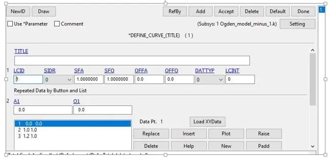
Define Curve:
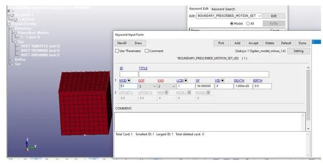
Prescribed motion set: To perform tensile test on cube we need constrain the set of node on translation Z-direction on top face of the cube.
Selecting NSID from set data using Set nodes and DOF 3 allowed in translation Z-direction and LCID define the displacement curve.
VAD=2 is given for displacement
SF – Scale factor set to 50 for displacement up to 50 mm. we have stretch ratio 5 given so to get the stretch ration we need displacement 50 mm.
Original length -10 mm and final length 50 mm.
Stretch ratio = 50/10 = 5
Steps involved in the Analysis:
- We have facility to solve implicit and explicit in LS-Dyna. The solver is able to solve static, Quasi-static, and dynamic problems
- Implicit and Explicit analysis differ in the approach to time incrimination
- In Implicit analysis each time increment has to converge, but you can set pretty long time increments.
- Explicit on the other hand doesn’t have to converge each increment, but for the solution to be accurate time increments must be super small.
- In implicit each time increment has to converge, but we can set quit long time increments.
- In explicit, converge for each time step is not needed.
- Implicit method, at each time increment, global equilibrium is established due to iterative method.
- Implicit method is used for accuracy and can be applied for long duration problems.
- Implicit analysis is suitable for this type of hyper-elastic material.
Implicit Cards
IMPLICIT AUTO: It is the one of the implicit card to initiate the implicit analysis by keeping DTMIN and DTMAX as zero to change time step automatically whenever it needed in the analysis.
IMPLICIT _GENERAL: To activate the implicit analysis method and initial Time step value is given as 0.05, Control _Termination is set as 1 and gives the value at which step the analysis will end.
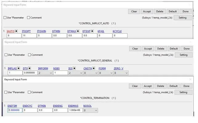
Database _Extent Binary: this keyword used to get the strain tensor data through D3PLOT, in solid elements, single strain tensor is written.
For animation we use DATABASE_BINARY_D3PLOT.
RESULT ANALYSIS
Here we can observe the stress contour in the block as we considered tensile force applied in the direction of Z.
And also maximum and minimum stresses in the block in translation Z- Direction
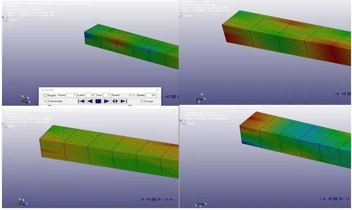
Strain in all four cases
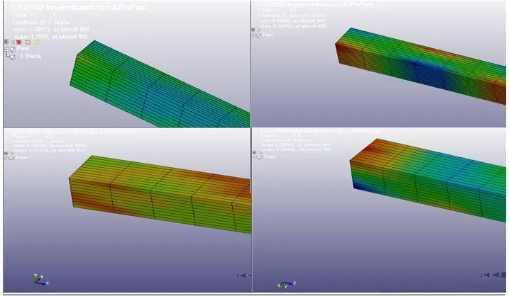
Maximum strain translation Z-direction is same in all cases which is 1.78
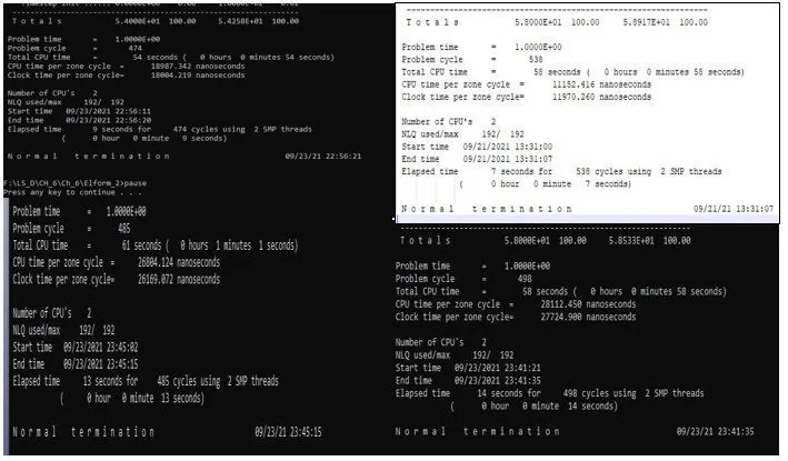
Calculations
Stretch Ratio: it is defined as the ratio between the final and initial length of the material. This is equal to 1+ Engg. Strain.
To get the stretch ratio, we need to get engineering stress and strain but we have true stress and strain available in our data. Here we can convert the true stress and strain into nominal or engineering stress and strain to get the stretch ratio. Stretch ration given as 5 in the given data.
Here we can find the engineering stress and strain using the following equations.
ϵt- True strain
ϵe – Engineering strain
λ – Stretch ratio
σt- True stress
σe – Engineering or nominal stress MPa
ϵt = In (1+ ϵe) =e˄ ϵt= (1+ ϵe) or λ
λ= e˄ ϵt
σt= σe(1+ ϵe)
σt = σe* λ
σe = σt/ λ
Excel data and Results
Calculations and graph are plotted
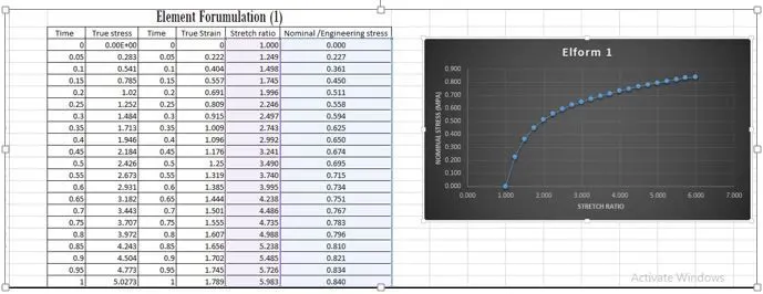
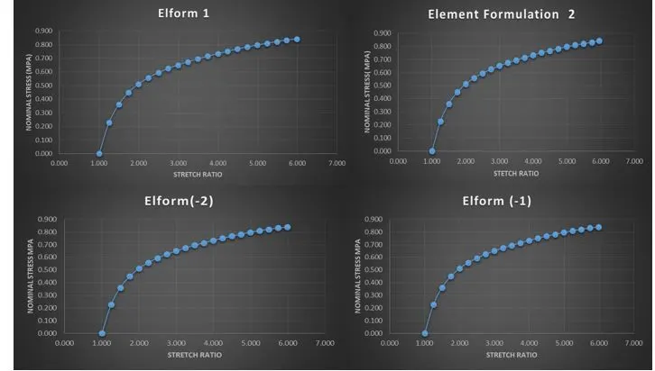
- Stress and strain behavior in all four cases are same and trend is almost same.
- Strain variation which is stretch ratio also same in different element formulation
- Stress is varying while stretching taking place, this is due to element elements behavior at different time period.
- We can also observe the time for solving different element formulation
Conclusion
- Stress and strain behavior in hyper-elastic material at different element formulation observed.
- Compared the results according to element formulation and observed the stress and strain.
- Plotted graph for all four case.
- Since the element formulation 1 is constant stress solid element, which is default and good for the strain energy function.
- For implicit problems ELFORM 2 is selective reduced integrated solid elements which gave constant pressure throughout the element to avoid pressure locking, but Elform 1 is more accurate than Elform 2 for implicit problems.
- Element formulations -1, -2 are fully integrated elements intended for elements with poor aspect ratios.so -1 is more efficient and type -2 is more accurate formulation.