Deploy connections using inbuilt NASTRAN solver deck in ANSA
AIM:
The aim of this project is to deploy necessary connections like bolts, hinges, weldments using the in-built NASTRAN Deck which is profoundly used for NVH analysis.
INTRODUCTION:
In few cases, the CAD data and files may contain the model of bolts, weldments etc. yet they don't actually imitate the required purpose. Hence these modeled connections are realized during the pre-processing stages to imitate their purpose. While in some cases, the CAD team doesn't necessarily have to model such components and often leave it to the CAE engineer to make the appropriate connections.
Pre-processing softwares like ANSA, HM come with in-built solver decks which contain the necessary features that are present in the original solver like LS-DYNA, NASTRAN. However these in-built decks are in no ways a mean of replacement for the original software since the solver algorithm is not in-builit in them rather they act as a means of making the model prepared (pre-processing) to export it onto the real solver for computation.
The type of solver deck chosen is mainly dependent on the type of application the model is used to perform. For ex, NASTRAN is widely popular in the NVH domain hence, our case, which involves a car door is pre-processed using NASTRAN elements so that it can finally be exported onto the NASTRAN solver for NVH analysis.
PROCEDURE:
1. Import the Nastran input file using the Input -> Nastran command
2. CREATE BOLTS USING 3DPOINTS:
At places where bolts have to be defined. Such places which should be bolted with two components at such places 3D points can be created using Topo -> Points -> On COG and then edges of a hole can be selected to create a COG point that can be used to specify the COG of the bolt that can be made around it as shown below,
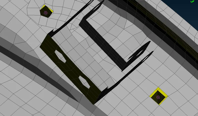
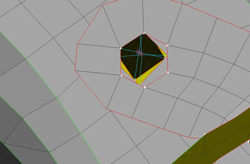
This point then has to be realized in the connections manager. After realization, the property of the parts where the bolt has to be created is selected and the zones of the bolt being created can be selected based on use of washer in the bolt. Similarly the dof of the bolt can also be defined such that a bolt can be constrained in 12345 i.e constrained at all 3 axis both in translation and rotational movement.
These 3D points then can be realized as bolts in the connections manager (as shown below)
3. CREATING RIGID BODY ELEMENTS
We can create RBE2 elements at places where joints and connections had to be made. Rigid elements can be created in Nastran such that it creates a multi-point constrained feature where more than one node on a single or more than one component can be constrained and its degree-of-freedom be constrained to that of one master node.
These rigid elements can be created using DECK MODULE -> ELEMENT -> RBE2 -> Many nodes/Two nodes
The many nodes can be used to create a cluster node and the two nodes can be used to create a stem of the bolt from two nodes where the hinge of the door is created.
While creating the RBE2 element it has to be defined as a new part which then can be grouped into a connections folder which contains every connection that are created in the model.
The hinge is created using DECK -> ELEMENTS -> RBE2 -> Two Nodes. This feature lets us select two nodes among which a stem element can be created and this can be realised as a hinge by restricting the constraint in dof about the z-axis i.e dof is selected as 12345
4. OTHER SMALL CONNECTIONS
The door and the rail mechanism are then connected to each other using cluster RBE2 elements which interconnects both components using a spider-like web connection that constraints the corresponding nodes.
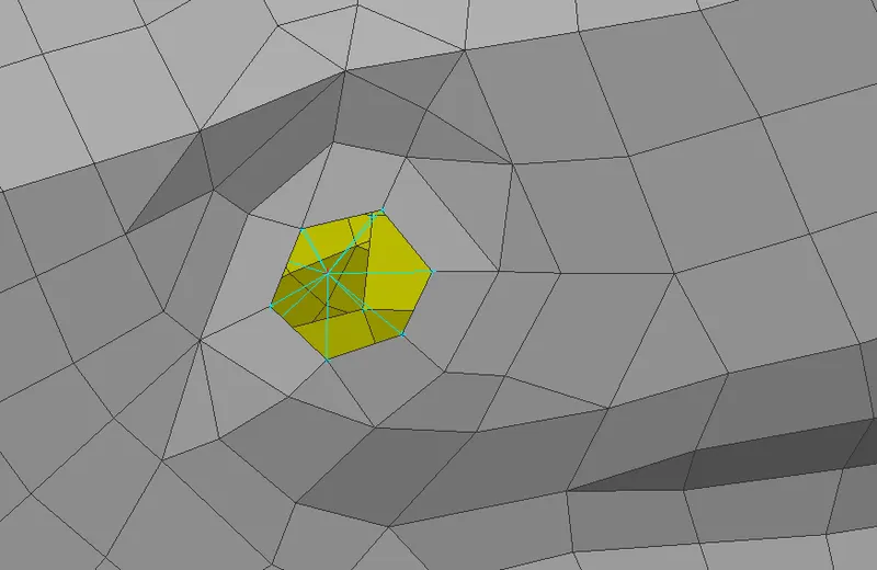
Note that connections at every hole is irrelevant and connections should neither be redundant meaning connections at where its necessary must be known by the engineer based on the application, function and feature of that particular component.
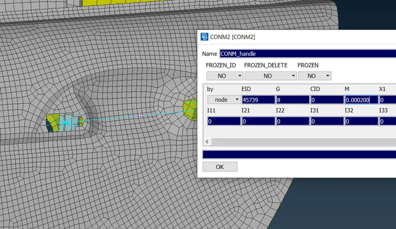
The door handle connection can also be made within the decks manager and dosen't necessarily have to be modeled as a CAD data. To create the handle first an RBE2 has to be created at either ends of where the handle is supposed to lie then a stem-like model which connects these two master nodes has to be created. Then the mass of the handle has to be specified by creating a COG at the mid point of the connection (handle) at which the mass should be an input in unit of Tonnes i.e 1g = 10^-6 Tonnes (as shown below)
5. WELDAMENTS
There are components in a car assembly model with few wedaments (i.e parts that are welded together at certain regions). These weldaments must be regonized by the CAE engineer if the CAD team fails to model or reference them.
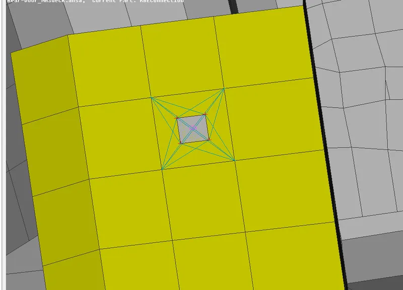
These weldaments can actually be welded by defining a weld contact between them using either a seam weld or spot weld (most common ones). To create a seam weld (at places with no line but only point contact) we should first create a point at that area using TOPO -> POINTS and then realize this 3D point as a spotweld in the connections manager.
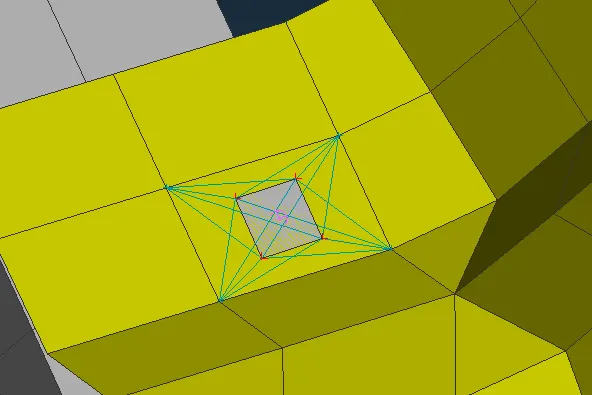
These spotwelds are modeled as RBE3-HEXA-RBE3 elements and their pinflags are modified to 123456 such that they are constrained in all degrees-of-freedom.
Similarly at other regions
6. MODELING WEATHER STRIPS AND WINDOW RAILS
Weather strips are a crucial component for the air-conditioning system in an automobile as they prevent heat transfer within the system and with the atmosphere.
Before realizing the connection as a spotline, curves have to extracted from the perimeter of the glass pane so that the weather strip which surrounds the glass pane can be modeled accordingly. To accomplish this we use the feat2curve command in Mesh which captures a line feature into a curve
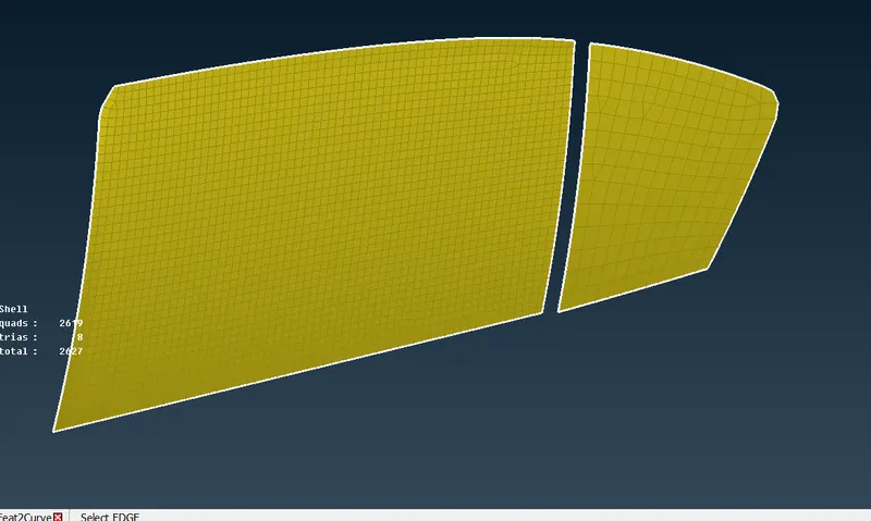
The created curves are converted into spotlines and then realized as a CBUSH element in the connections manager. The CBUSH feature lets us specify value of damping coefficients to the connection which imparts a stiffness-like feature to it just as how beads in the weather strips offer a damping effect to the glass pane as it slides down.
This helps us create a bead like element around the perimeter of our glass pane which acts as a weather bead. The create element has a different CS and its local coordinate dosen't necesarily have to be aligned with the global coordinate.
After successfully realising all connections as CBUSH elements for the weather strip, it would look like as shown below
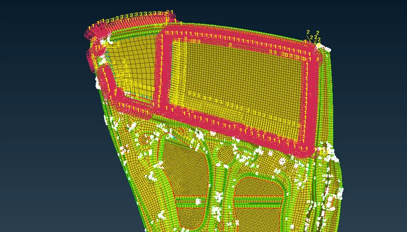
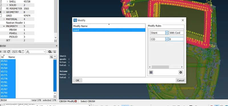
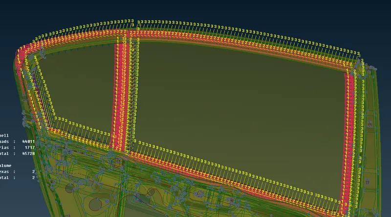
These newly created elements are aligned w.r.t its own axis i.e its local coordinate system. Hence due to this each element is aligned differently based on the alignment of the parts that it represent. So to change this the entire CBUSH eleements can be modified to align with the global coordinate (as shown below)
CONCLUSION:
Thus the entire rear door model of an automobile is pre-processed by defining the required connections. It is the sole responsibility of the engineer to realize such connections during the pre-processing stages and then it can be successfully exported to the solver for computational purposes.
LEARNING OUTCOMES:
Gained knowledge on:
Creating RBE2 elements are crucial parts
Creating bolts using just points
Creating spot and seam welds at weldment components
Creating CBUSH element to define the weather strip in an automobile.