CONNECTIONS (REAR DOOR)
CONNECTIONS (REAR DOOR)
Aim:-
- Understand the different type of connection or constrains in ANSA software.
- Open rear door FE model in ANSA observe the type of connection you could deploy according to front door model.
- Provide connection to the model with respect to their function and movement.
- Identify and convert 1D element.
- Lastly, write report on each connection and why particular part connecting certain part.
Objective:-
- Open the Rear Door model FE model in ANSA.
- Provide separate Property ID to every part for easy observation and fast handling.
- Observe model and find out the area where connection is needed.
- According to working or movement connect all the are one by one using proper connection technique from ANSA toolbar.
- Find if there any element that can be convert into 1 d element and convert it.
- Finally, create report on the connection of element and reason behind each connection.
Import Model:-
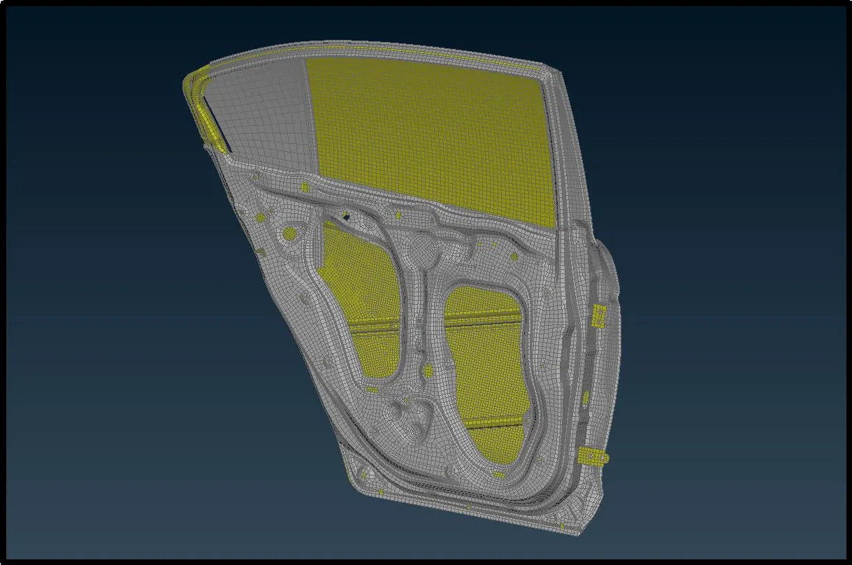
In this project our first step will be importing the FE model in ANSA. We can do in by drag and drop method or using open option from file menu in ANSA. After, we open the model, it will look something like this.
Set PIDs:-
There are plethora different parts which is assign to same Property ID which is hectic for any user to find or identify different parts because of same color. So our first task should be to assign different property IDs to each individual parts. By doing this, firstly, we can see each part with their unique color, better to identification of various part. Secondly, separate PIDs latter help us to assign different thickness to every parts.
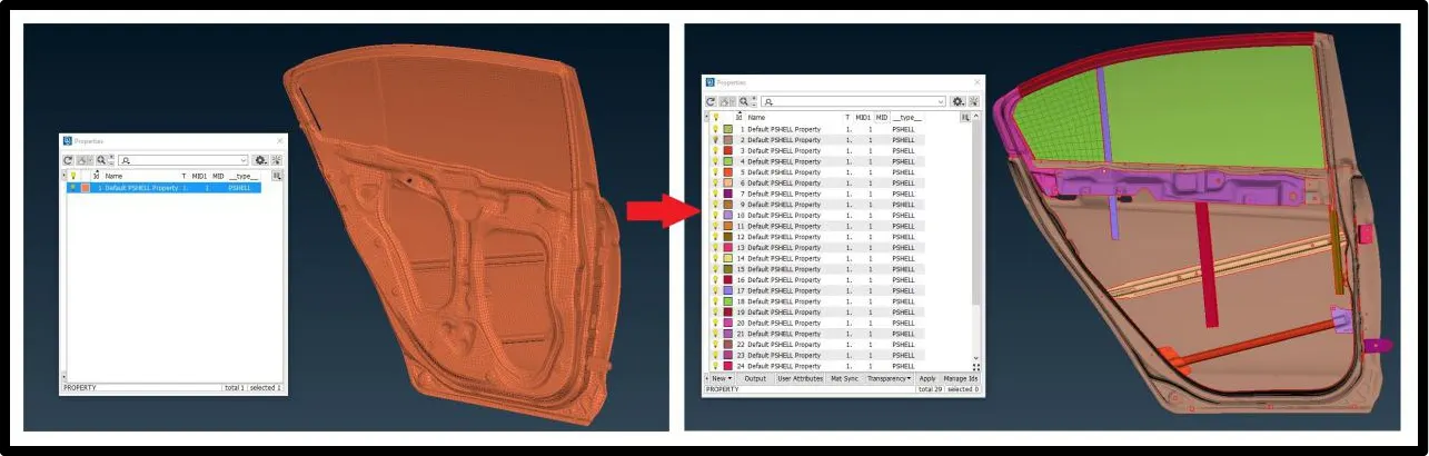
From hear we can start deploying connection to the part, in this, first, we are going to use bolt connection.
Bolt connection:-
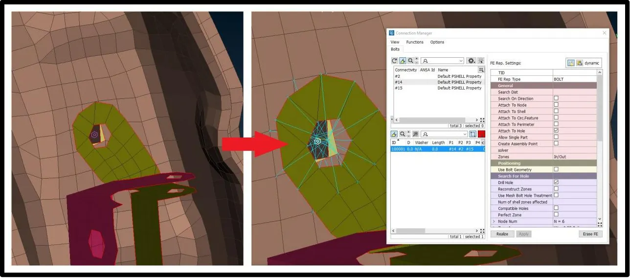
Bolt connection can be use between two or more align holes of various surfaces. For this first we have to create center 3D point in hole of the middle surface using on COG point button and and then convert that 3D point to the bolt using convert button on top panel.
Then using connect button select the bolt symbol and select parts to be connected and deploy bolt connection on that part.
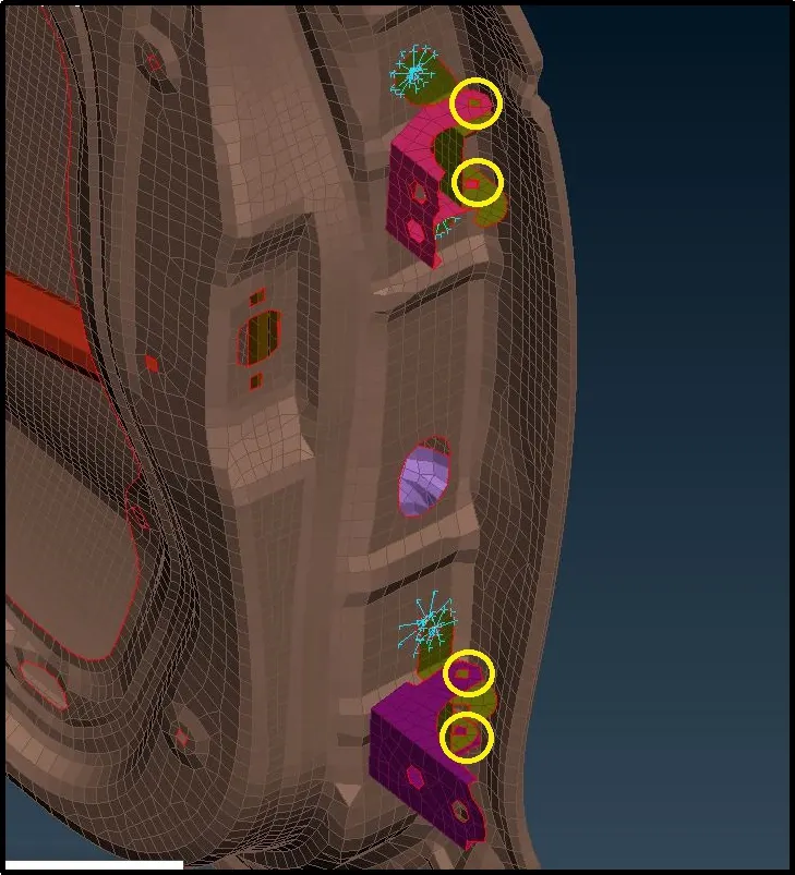
In out FE model we have to connect yellow circled section by bolt connection where all the part have hole align to each other which can be connected by bolt.
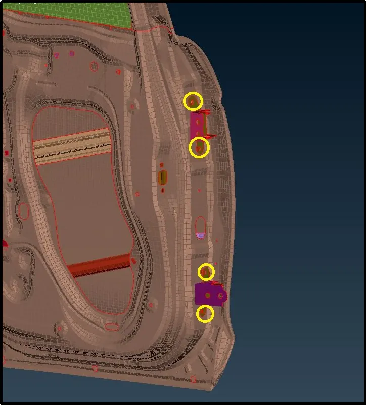
To this four area create 3D point and convert it into bolt and generate bolt connection following way.
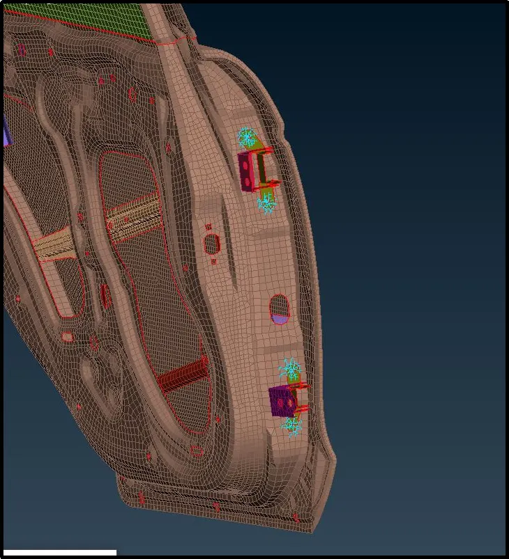
Next connection we are going to use RB2 connection.
RBE2 (MANY NODES):-
Defines a rigid body element of form 2 (RBE2) between selected grid points, 3D-points etc. This element is a rigid body with independent degrees of freedom specified at a single grid point and with dependent degrees of freedom at an arbitrary number of grid points.
RBE2 (TWO NODES):-
This function defines a rigid body element of form 2 (RBE2) between two selected grid points, 3D-points etc. This element is a rigid body with independent degrees of freedom specified at one grid point, and with dependent degrees of freedom at the other grid point. The node with independent degrees of freedom is the one that is selected first.
On following are, shaded in yellow, we are going to deploy above both connection.
First, on each hole we are going to deploy separate RB2 many nodes elements which master node we well use to connect the RB2 connection with Z-Rotational degree of freedom as door going to rotate along z-axis.
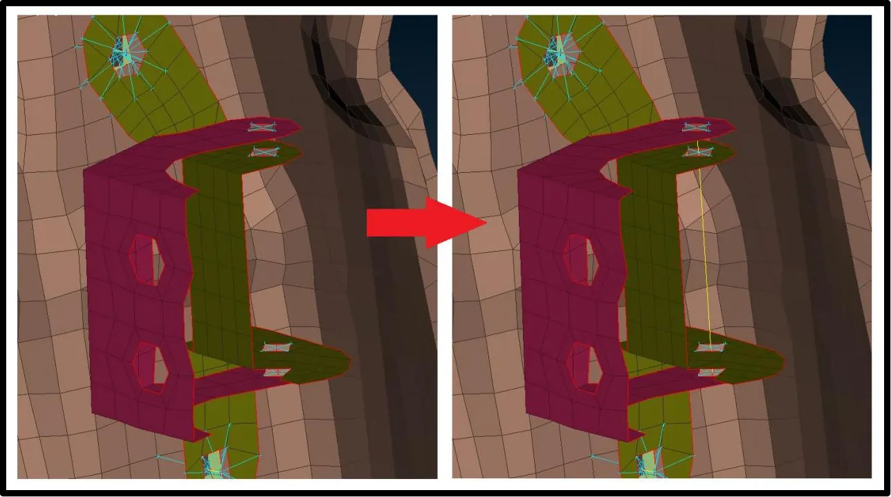
For rotational degree of freedom along z-axis we are going to remove 6th constrain .

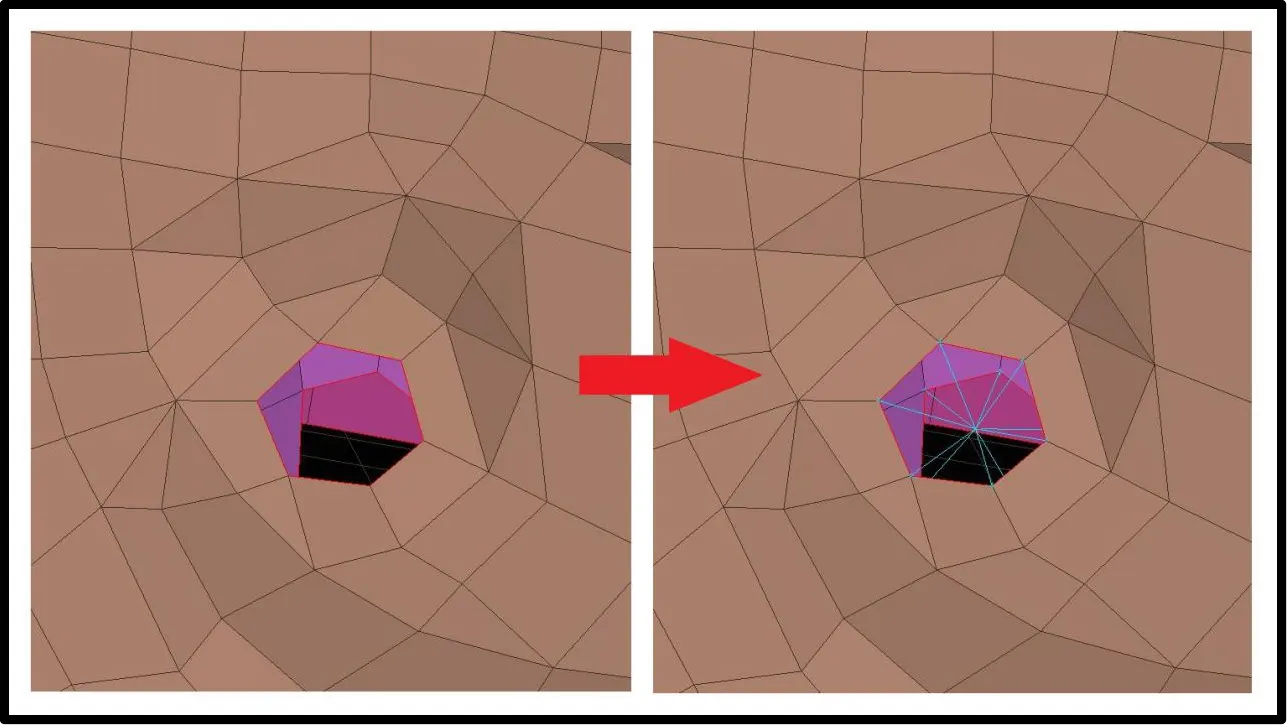
In next case, we will create washer before deploying the RB2 connection. We use this technique when we know some part are going to connect with other part through particular hole. That specific holes must be fixed with inner and outer element nodes of that zone cut of the washer.
Such as following part, which going to connect to the car body we fix it with RB2 Multiple nodes by creating washer around the holes.
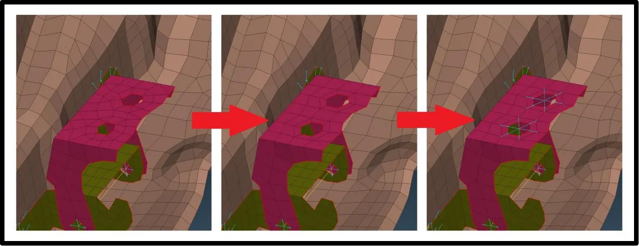
Other small areas, where small hole can be connected by bolts, Rivets, or by welding, such areas can be directly fix with each other using RB2 such as following areas or holes.
Spot Weld:-
Spot Welding is one from of the resistance welding, which is a method of welding two or more metal sheets together without using any filler material by applying pressure and heat to the area to be welded.
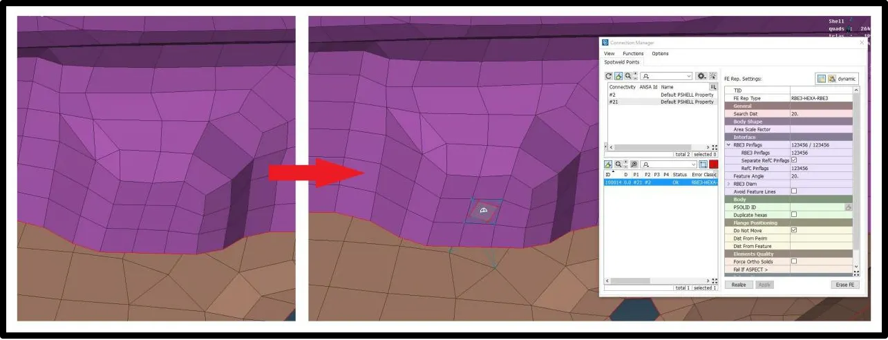
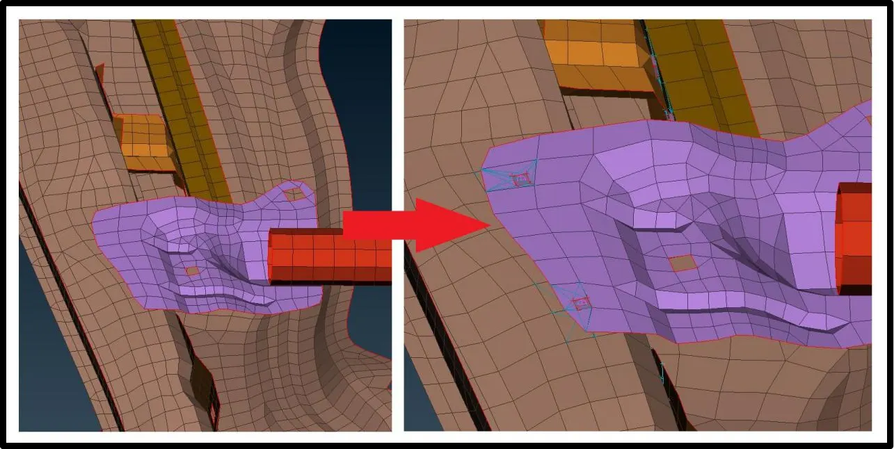
Some surfaces of the parts are close to each other to be weld together using spot welding this connection can be deployed in ANSA
Spot weld connection method goes exactly like the bolt connection, first, we have to create 3D point using On COG Button. Then using convert Button convert that point to spot weld point.
Next using connection button, select spot weld point point and in connection window select part to be connected using spot weld and using spot weld section realize the connection.
Similar to all following sections, we will employ spot wild connection to connect parts.
Overlap welding:-
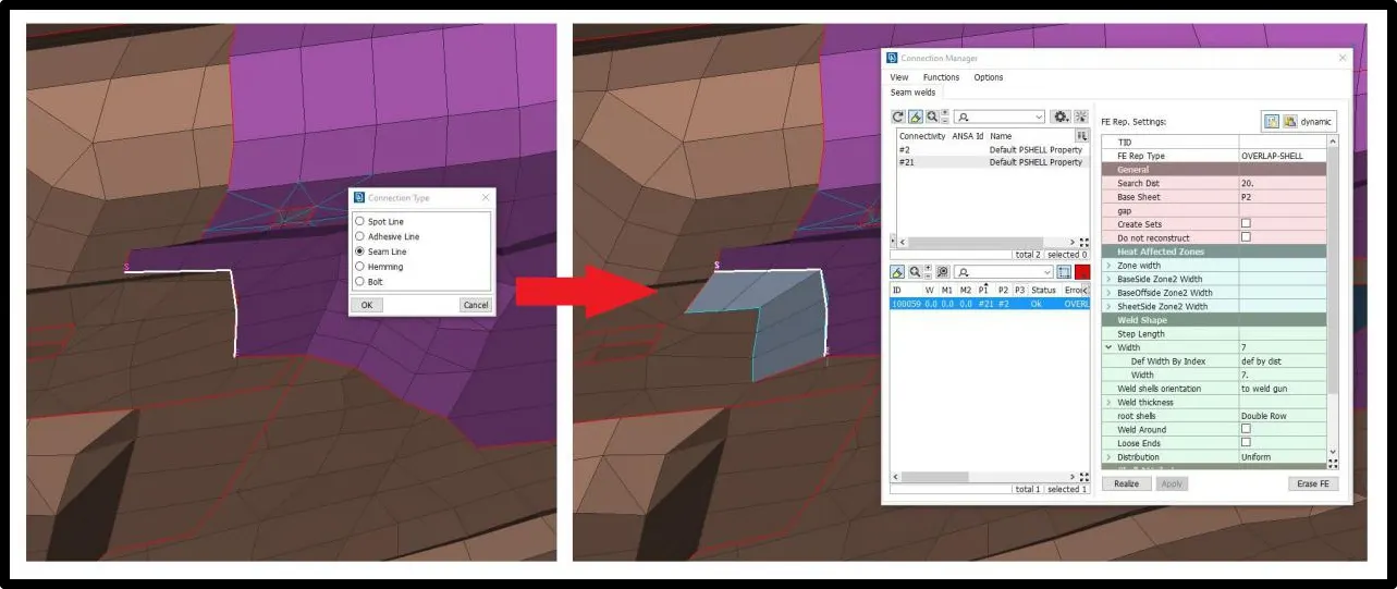
On the overlap surface to deploy proper weld connection we can use overlap wending. To generate this type of connection first we have to create curve using FE to curve button and convert it to seam line. Use this seam line to connect two part which is overlapped to each other and which mean to be connected by welding.
Following section can be use as best representation for the overlap welding.
Y-joint shell weld:-
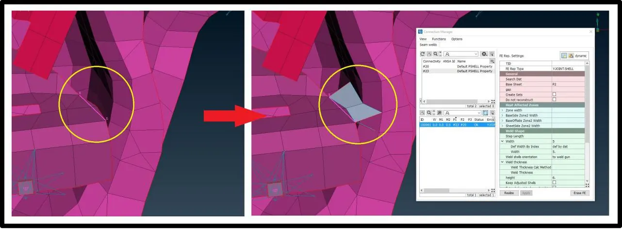
Y-joint places where parts which are likely to be place perpendicular to each other or somehow forming T joint. Y-joint can be employed same way as Overlap joints. Following section is the representation for the y-joint.
Bush Connector:-
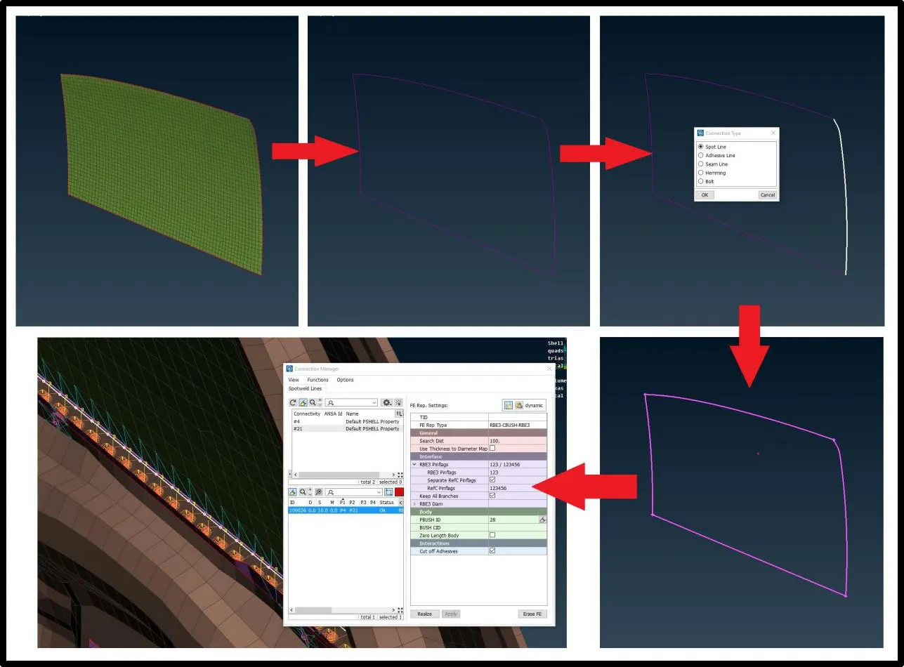
Bush connection use to place connection between the parts which is connected by damping elements for cushioning effect to brittle glass in this particular case. By providing the bush connection we can provide proper stiffness as per the material, but in current case we are going to assume it. First, from mesh panel we will use Fea2curve button to extract the curve from the border of the glass. Next, convert those curve, individually, into spot line and using that spot line we are going to create bush connection.
In connection window select two part to be connected also provide spacing and in FE resp tab select RBE3-CBUSH_RBE3. In that panel give search distance element dist of two parts (40-60). assign property ID and realize the connection.
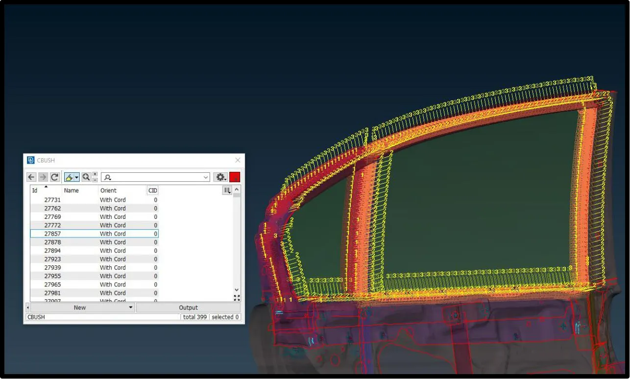
Generation of bush elements may have different vector direction which can create deviation in our simulation results. So we align all the vector coordinates as global coordinate by changing CID value of each bush element to zero.
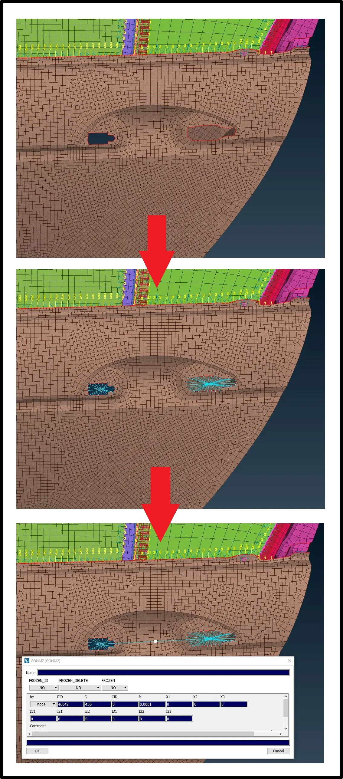
RBE2 Connection for Door Hinges:-
In this connection we will fix two hole for the handle using RBE2 rigid elements. This connection will give us 2 master nodes for handle.
After fixing 2 master nodes, by using CONMi button we will provide mass of the handle as 100 grams. ANSA take value in tonnes to we will put 100 grams as 0.0001 tonnes in element mass.
1 D Element:-
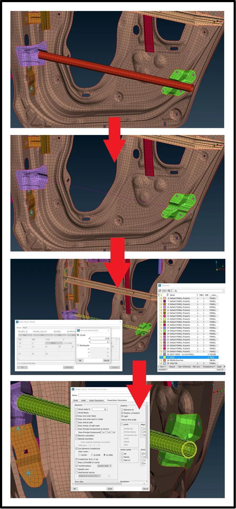
Part with the same cross section all over its length can be considered and converted into 1D elements. In car rear Door geometry there is one hollow cylindrical part can be considered as 1D element.
To convert it we first have to create centre curve. Then using CBAR button mention the element size and create PBAR property in which mention Outer radius and thickness if part is hollow cylinder. We can see solid view by turning on line Elements Cross-section panel in Quality window in Presentation Parameters panel.
Conclusion:-
- Learned various connection in ANSA according to type of different actual physical connection between parts.
- Successfully deployed every connection to the Rear Door model and made it properly constrained ready for the simulation analysis.
- Converted 1 cylindrical cross section part as 1D element which can be viewed as solid model by turning on line Elements Cross-section option in Quality window in Presentation Parameters panel.
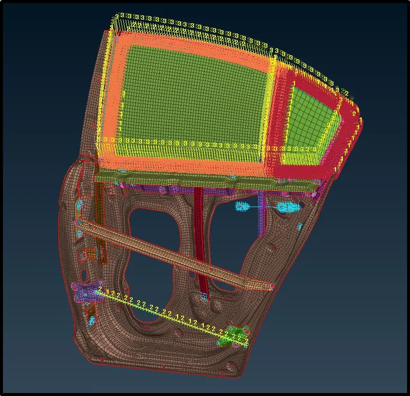
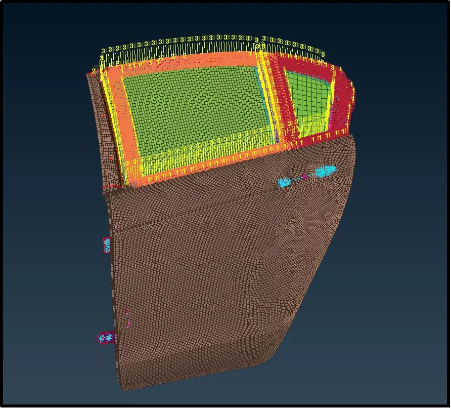
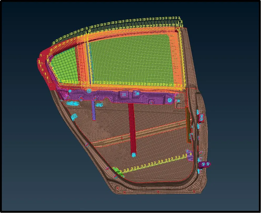
Constrained view of the model:-