Week 5 Sphere pressing on a plate
AIM: - PERFORM THE SIMULATION OF A SPHERE PRESSING ON A PLATE SURFACE.
The simulation to be performed is of a sphere pressing on a flat plate. The material for both the objects is Structural Steel but for the plate, it will be Structural Steel NL.
The sphere will be pressed onto the flat plate up to a distance of 4 mm and then retracted.
To begin with, the analysis, launch Ansys Workbench and select the Static Structural analysis from the Analysis systems.
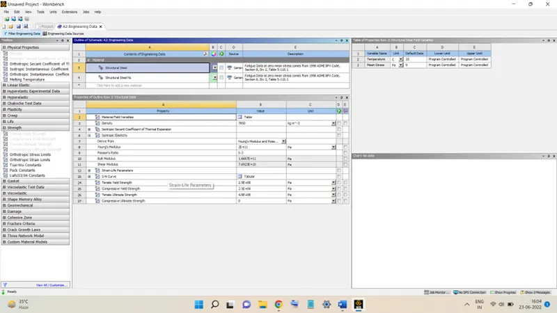
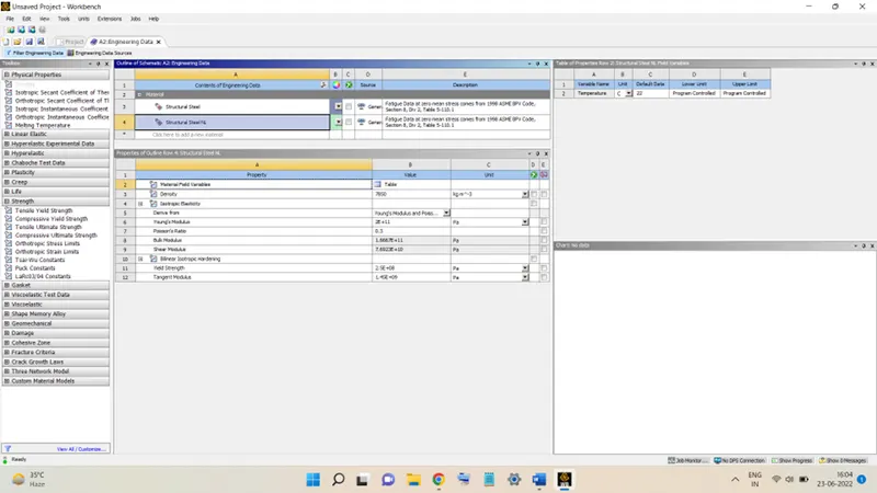
Double-click on Engineering Data and then go to Engineering Data Sources. In it, select General Non-Linear Materials and from there select Structural Steel NL and add it to the project library. The properties of both materials are shown below:
1. Structural Steel:
2. Structural Steel NL:
Next, import the required geometry into the project environment. Double-click on Geometry to launch SpaceClaim and load the geometry in it.
The geometry will look like this:
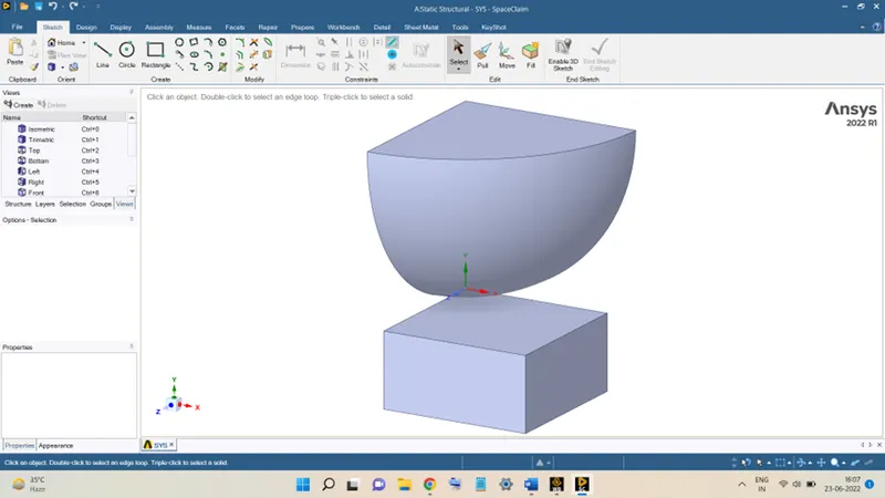
The geometry is like this due to the inherent symmetry of the setup. The current geometry is only the one-fourth portion of the entire geometry. Since the Sphere and the square plate are symmetric about two different axes therefore the analysis can be conducted on the one-fourth portion and the results from it afterward will be mirrored on both the axes of symmetry.
Now, right-click on Model and select Edit to launch the geometry in the Mechanical Module, it will look like this in the module:
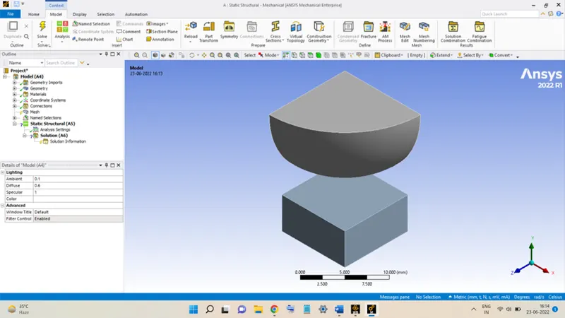
The first step is to expand the Geometry options and rename the parts as shown below:
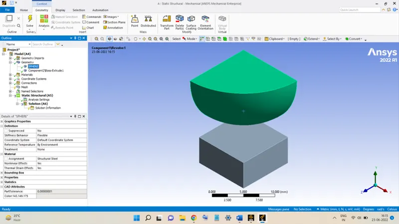
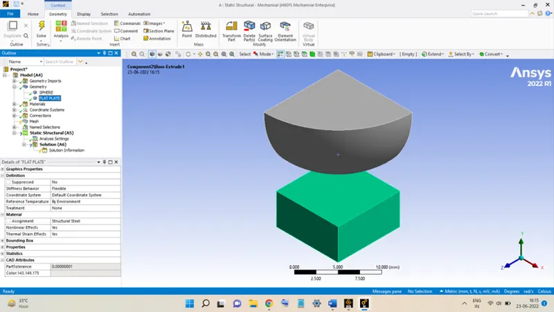
Select the FLAT PLATE body and change the Assignment to Structural Steel NL.
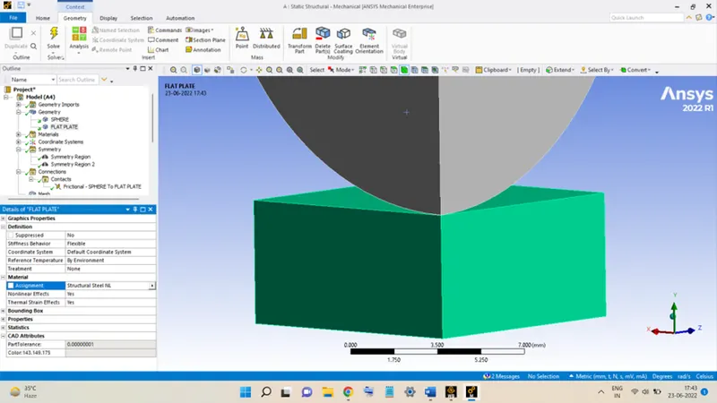
Delete all the pre-defined connections assigned to the geometry and assign new contacts by right-clicking on Contacts and going to Insert and selecting Manual Contact regions.
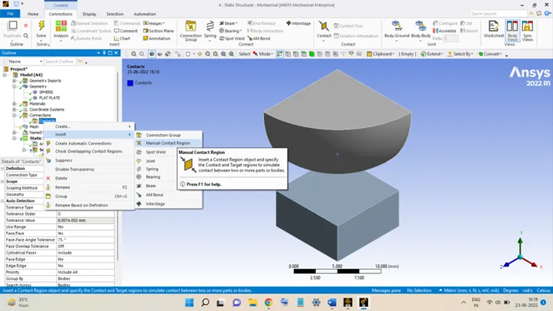
Select the curved surface of the SPHERE as the Contact Region and the top surface of the FLAT PLATE as the Target Region and hit Apply.
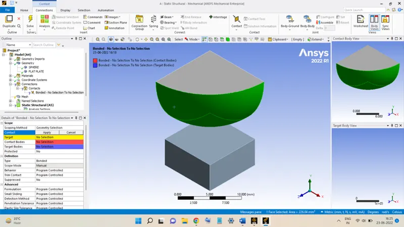
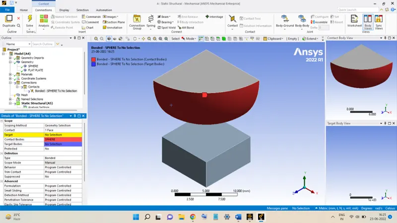
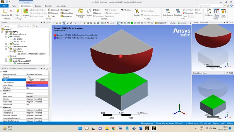
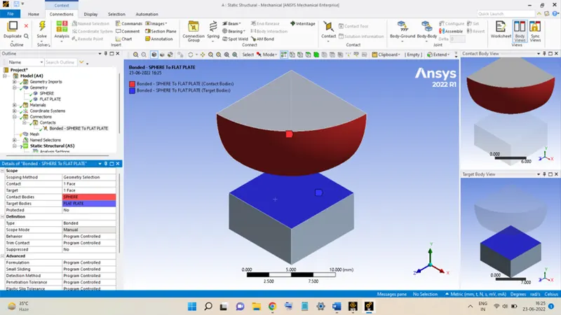
In the Definition section, change the Type to Frictional, and the Friction Coefficient value is taken to be 0.74 (as mentioned in the Roymech useful Tribology Table).
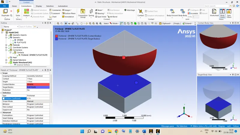
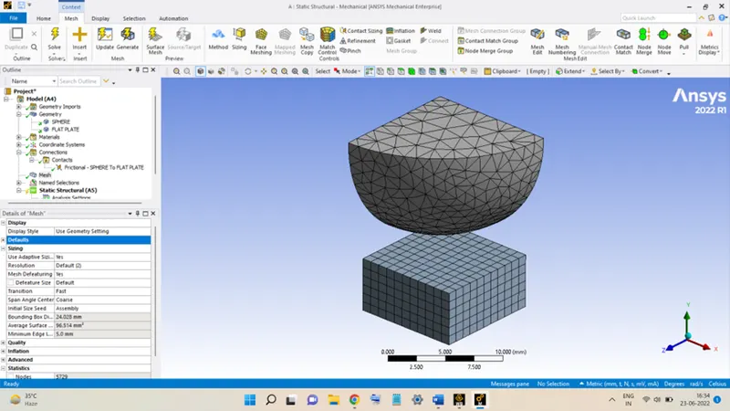
The next step is to mesh the model, to mesh the model right-click on Mesh, and select Generate Mesh. the mesh generated will look like this:
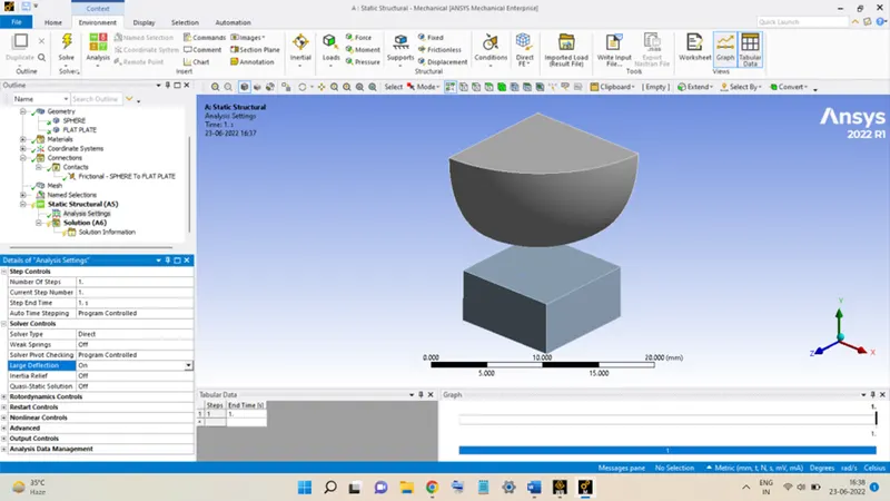
The next thing to do is assign the Analysis Settings to the model. In the Analysis Settings, set the Number of Time Steps equal to 4. In the Solver Controls section, take the Solver Type to be Direct and turn the Large Deflection ON.
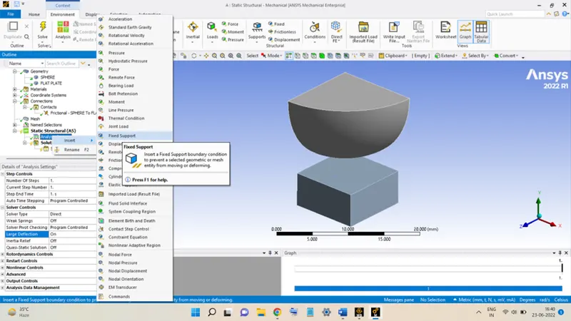
Now to fix the FLAT PLATE, right-click on Analysis Settings go to Insert, and select Fixed Support. Select the Bottom surface of the FLAT PLATE and click on Apply.
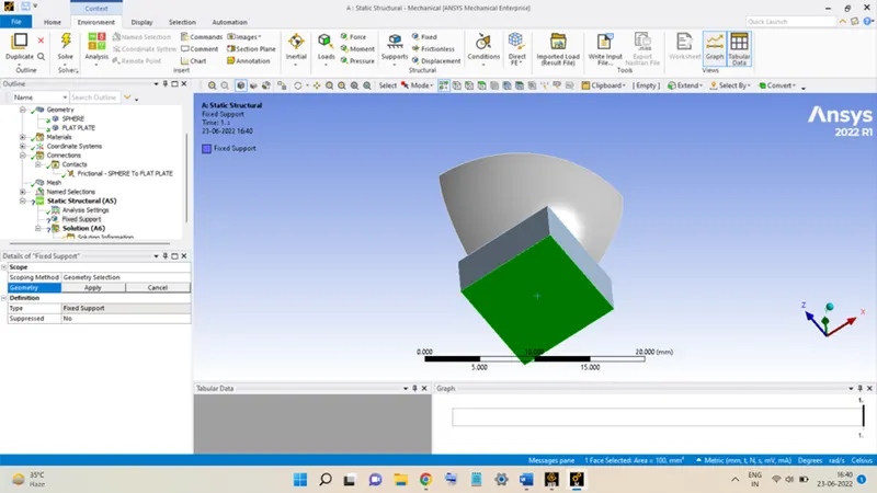
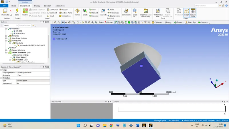
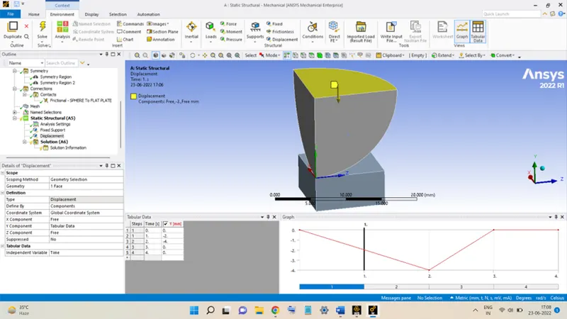
Now, give the necessary displacement to the SPHERE. The SPHERE is required to move a total of 4 mm into the FLAT PLATE (in negative Y-direction).
To do so, right-click on Analysis Settings, go to Insert, and select Displacement. Select the top flat surface of the SPHERE and hit Apply.
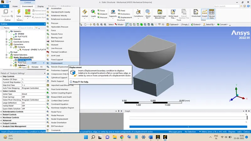
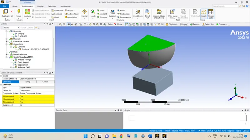
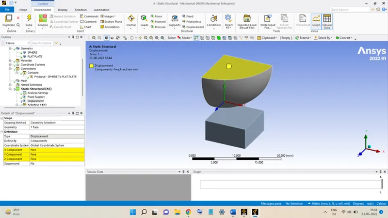
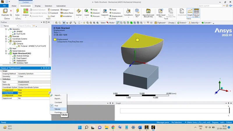
Since the displacement will take place in a negative Y-direction, change Y-Component to Tabular. The values entered in the table are such that, the SPHERE will first move into the FLAT PLATE till 4 mm and will retract back, as shown in the figure below:
The next step is to assign the Symmetric Regions for the model. To do so, click on Model and select Symmetry. It will add a new section in the design tree named Symmetry.

Right-click on Symmetry, go to Insert, and select Symmetric Regions. Select the surfaces of the SPHERE and FLAT PLATE, as shown below, and hit Apply.
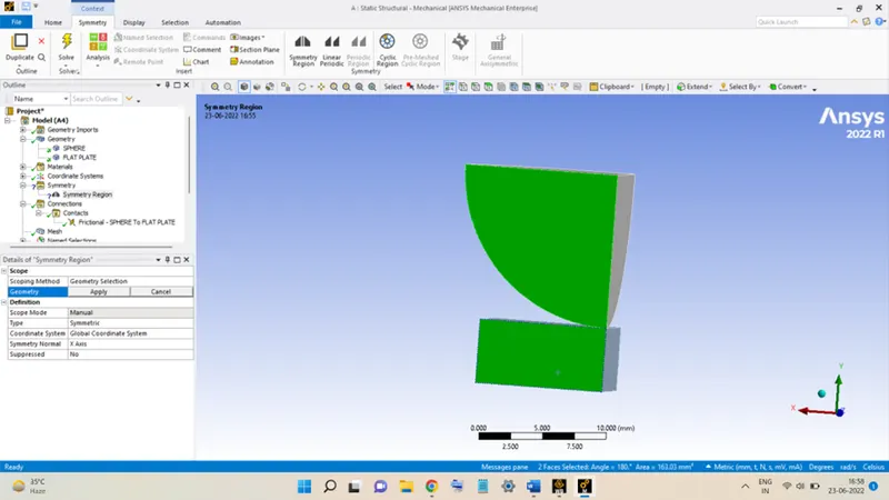
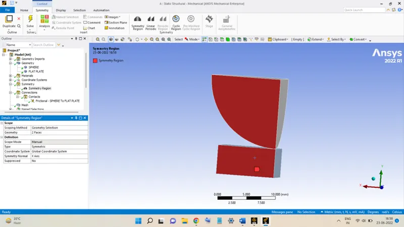
The surfaces selected will have the Symmetric Normal along Z-Axis, so change it to Z-Axis.
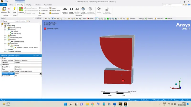
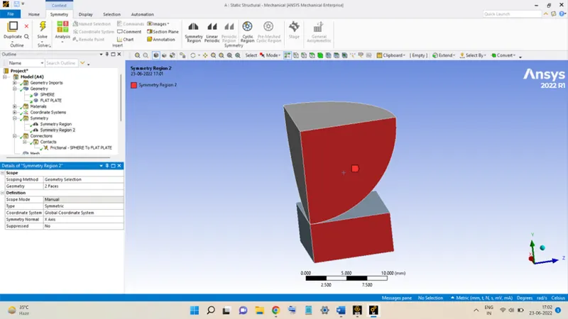
Similarly, add another symmetric region and select the other two faces and for them, the Symmetric Normal will be X-Axis, as shown below:
The next step is to add the output parameters of the analysis. The required outputs from the analysis are:
Deformation of FLAT PLATE and SPHERE.
Stress developed in the setup.
Plastic Strain in FLAT PLATE and SPHERE.
After adding all these parameters, the model is ready for the analysis, click on Solve to begin.
RESULTS:
Equivalent Stress in setup:
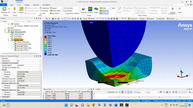
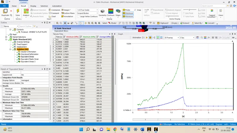
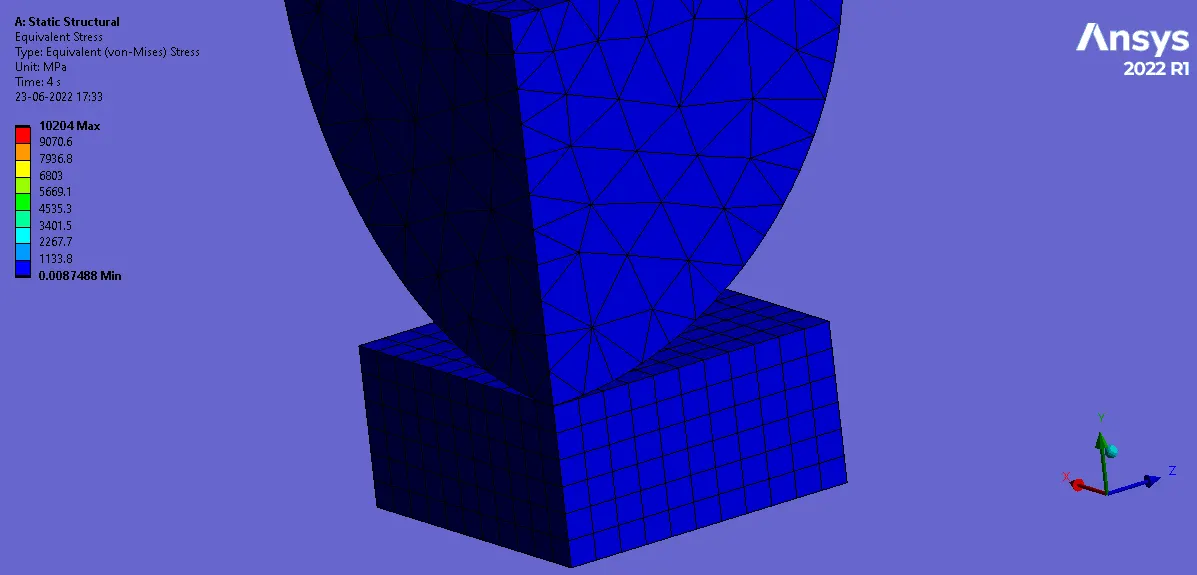
The above figures show the variation of the stress developed in the setup. The stress reaches up to a value equal to 10204 MPa.
Equivalent Stress in FLAT PLATE:
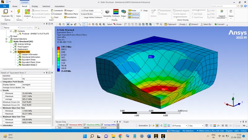
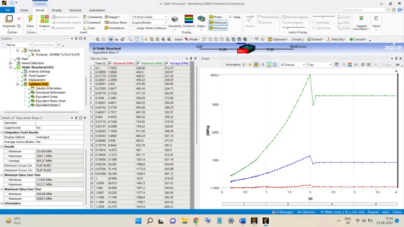
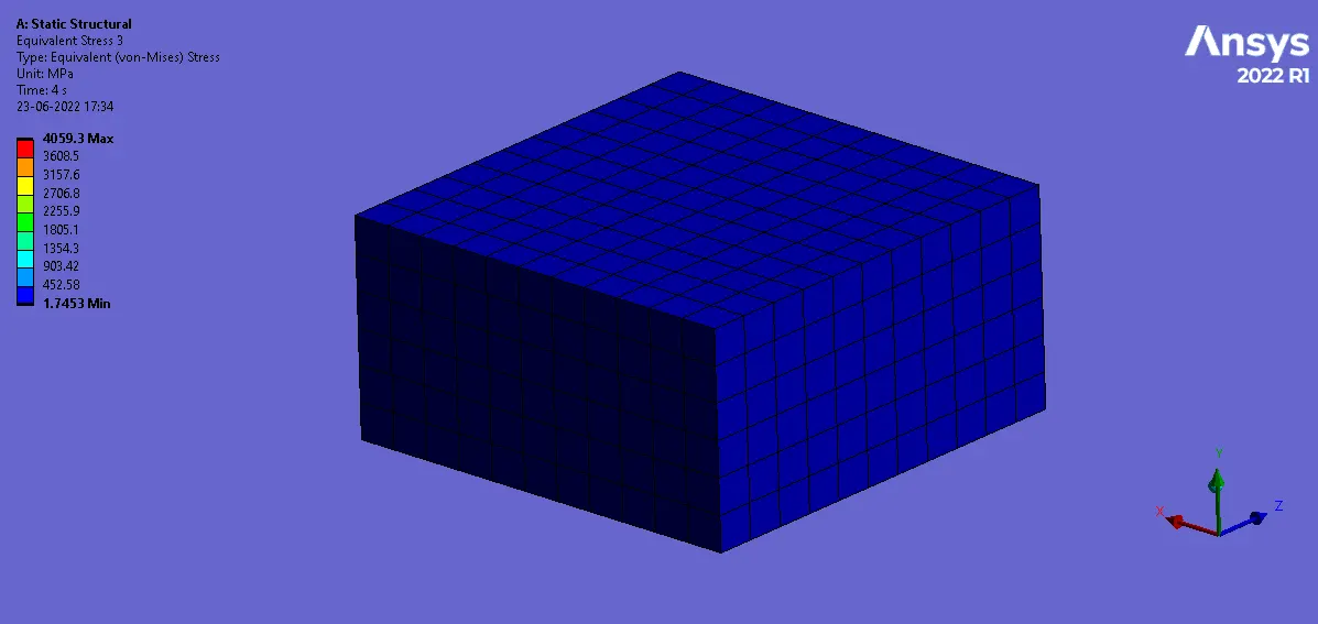
The stress in the FLAT PLATE due to SPHERE advancing in is shown above. The stress reaches a maximum value of 4059.3 MPa at the point where the SPHERE is pressed up to a maximum distance (4 mm). after the SPHERE is removed the stress value decreases and gets constant for the rest of the time.
Stress in SPHERE:
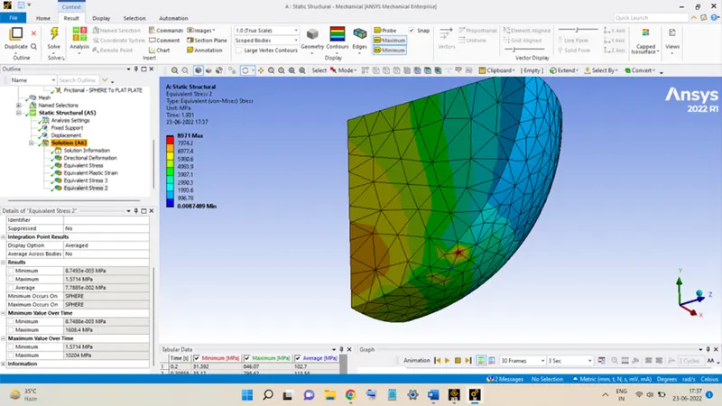
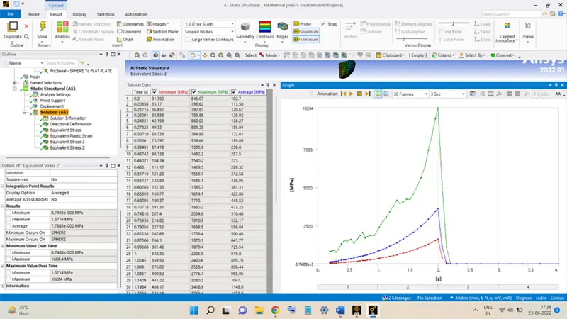
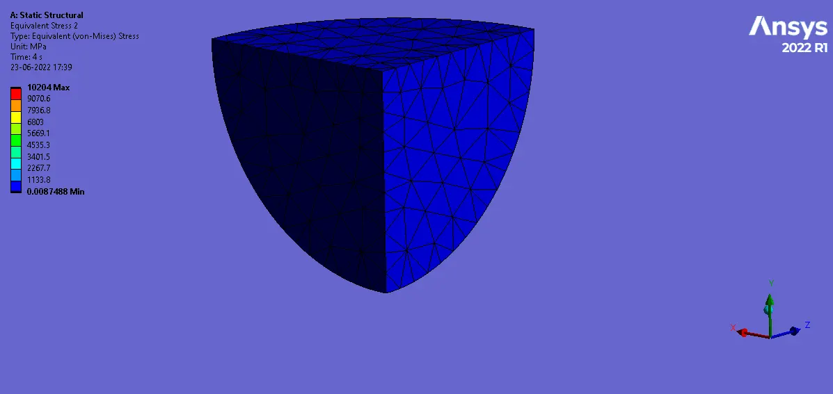
The stress developed in the SPHERE is shown in the above figures. The stress increases till the SPHERE is pressing against the plate and then after it is removed, the stress in it sharply decreases.
Plastic Strain in FLAT PLATE:
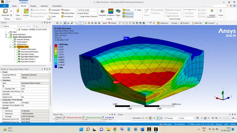
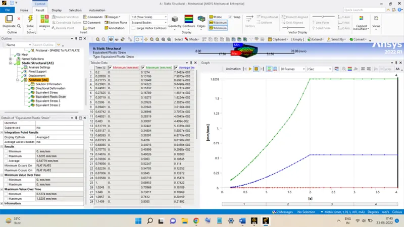
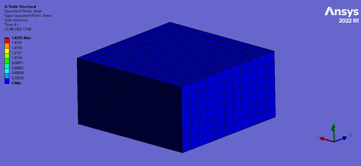
The variation of the strain in the FLAT PLATE during the pressing operation is plotted in the above figure. There is a monotonic increase in the strain till the SPHERE is pressing and the curve flats out as soon as it is withdrawn. Thus, it can be safely said that the strain is the Plastic Strain and its maximum value is equal to 1.8205.
Deformation in Y-Direction:
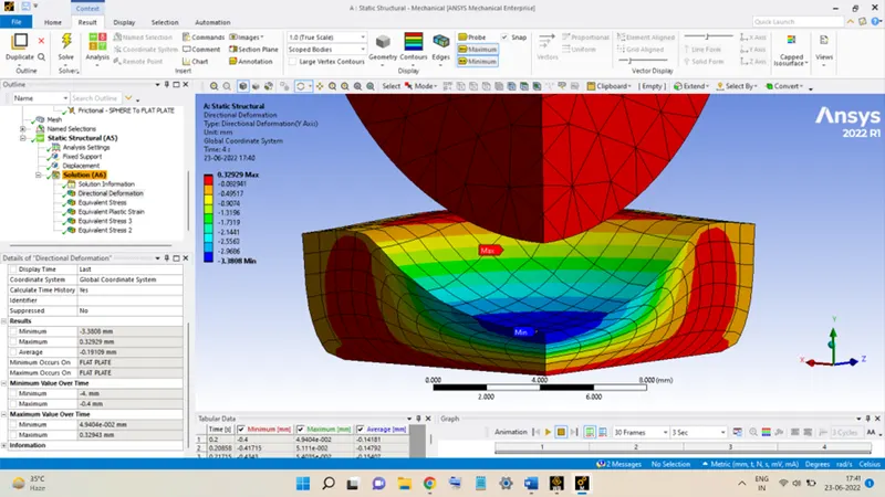
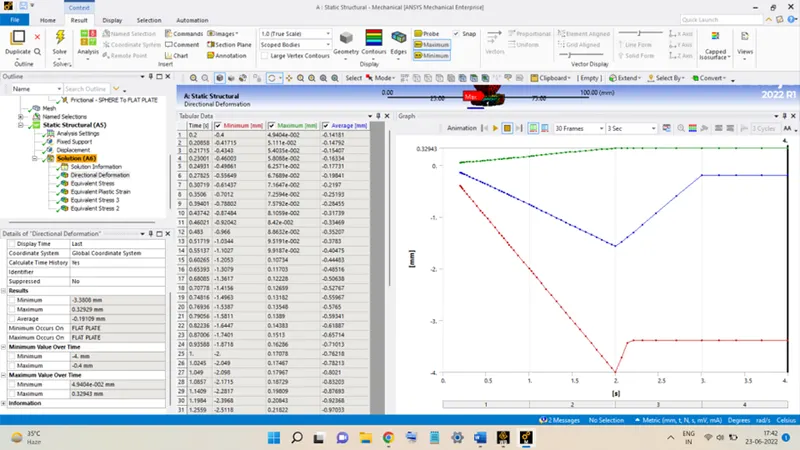
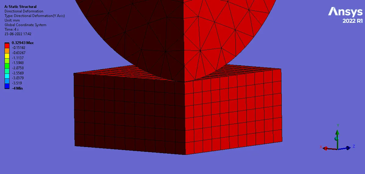
The FLAT PLATE deforms due to the pressing action and the maximum deformation experienced by the plate is equal to -4 mm (negative sign signifies the deformation occurring in negative Y-Direction).