Week- 5 - Solid meshing
For the given Rear view mirror component, check for the geometrical errors and mesh the Surfaces with the given 2D element Quality criteria given below.
|
S.No |
Quality Criteria |
Value |
|
1 |
Target/Average length |
1 |
|
2 |
Minimum Length |
0.5 |
|
3 |
Maximum Length |
2 |
Use tetra elements to mesh the Volumes defined in the model and check for the below quality after Volume meshing.
|
S.No |
Quality Criteria |
Value |
|
1 |
Tet collapse |
0.2 |
Procedure:-
- Import the CAD model into the ANSA workspace.
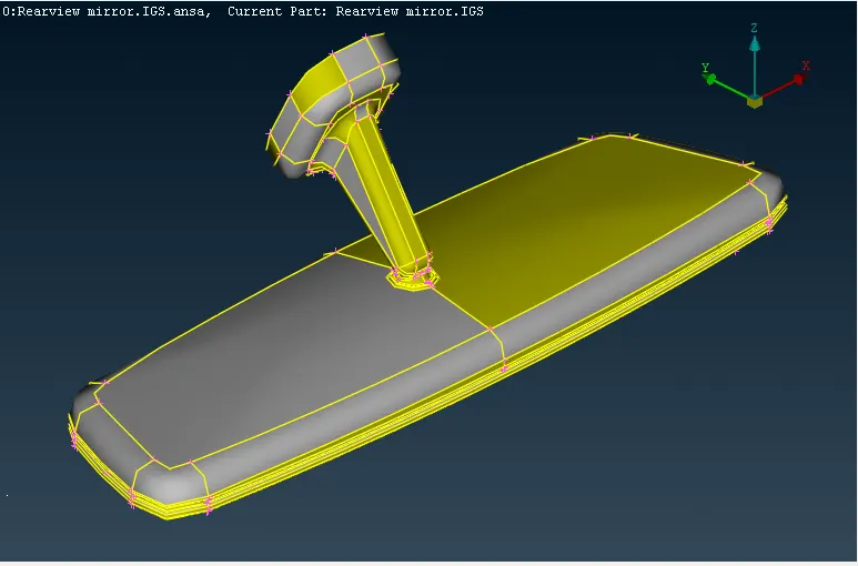
- The imported CAD model has no connected surface thus the surfaces are needed to be connected using Faces>Topo. These commands help in connecting faces resulting in connected surfaces using double cons.
- The orientation of the CAD model is changed using Orient> Visible and Orient> Select functions in the Faces Tab.
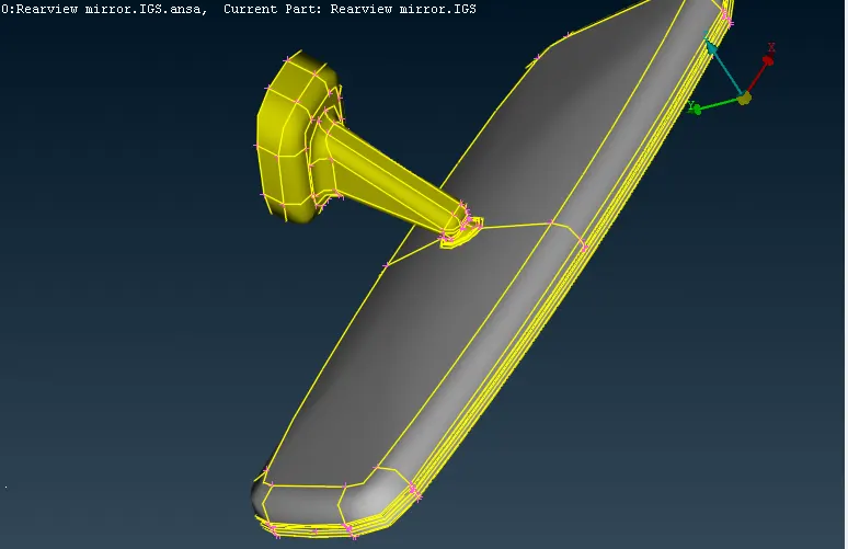
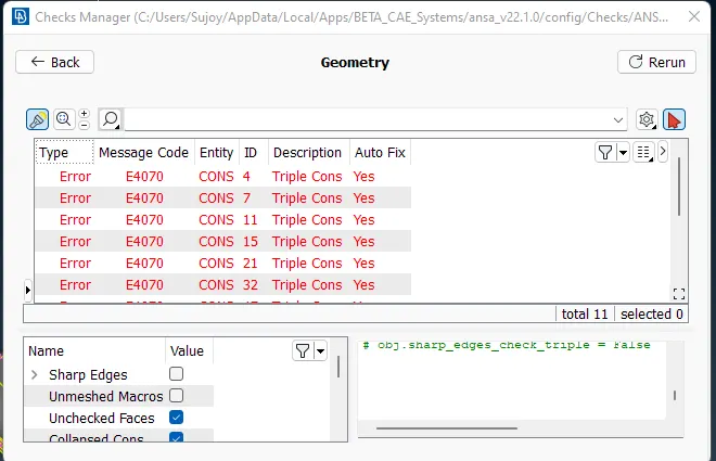
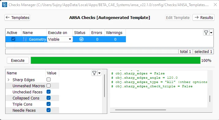
- As the TOPO function is run, the command has resulted in triple cons in the geometry. Thus the geometry check is run to fix the errors.
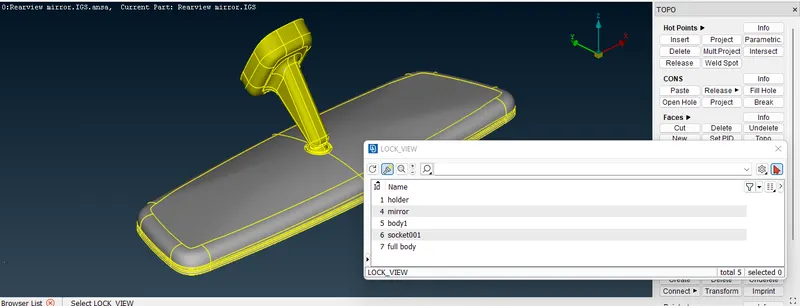
- The CAD model after fixing errors is divided into 4 parts namely, the holder, body socket, and mirror.
- We can now smoothen the Perimeters and Macros for better visualization of the CAD and check for any surface irregularities, i.e. raised portions or kinks, etc.
- It is noted as seen in Fig 7 that there are no issues with the geometry and further operations can be done.
- By Meshing, it is meant that the surfaces that define the boundary of the volume of each component part, are to be shell-meshed, and the volume mesh can then be generated as explained in this report further.
- Since we have already separated the component parts of the given CAD model in different locked views, it is easier for us to work on one component at a time i.e., defeature and mesh the components one by one.
- First of all, we need to define the Mesh Parameters and Quality Criteria as per the given data.
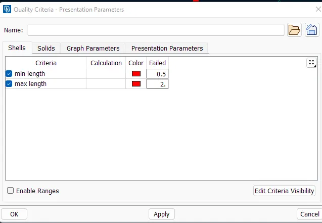
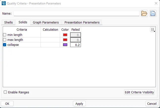
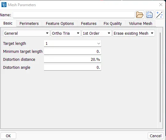
- the element type has been selected as Ortho Tria. This is done because we will first shell mesh the curved surfaces of the Component using the Ortho Tria elements which give better surface coincidence with the mesh as compared to regular Tria elements.
- We start defeaturing the CAD and shell-meshing the components one by one.
- We start defeaturing the mirror. By using spot-mesh we start meshing the mirror. The fillets are to be meshed first by selecting spot-mesh and ortho tria.
- The mostly flat surfaces are meshed using regular Tria elements as they do give flat mesh with no kinks or raised peaks as well as take less time for computation as compared to Ortho-Tria elements.
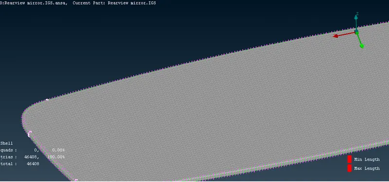
- Now, we can work on the other component parts in the same way, i.e., by first defeaturing necessary features in the components and then shell-meshing the components' curved surfaces with Ortho-Tria elements and finally shell-meshing the flat surfaces with Tria elements
- We can now work on the other component parts in the same way, i.e., by first defeaturing necessary features in the components and then shell-meshing the components' curved surfaces with Ortho-Tria elements and finally shell-meshing the flat surfaces with Tria elements.
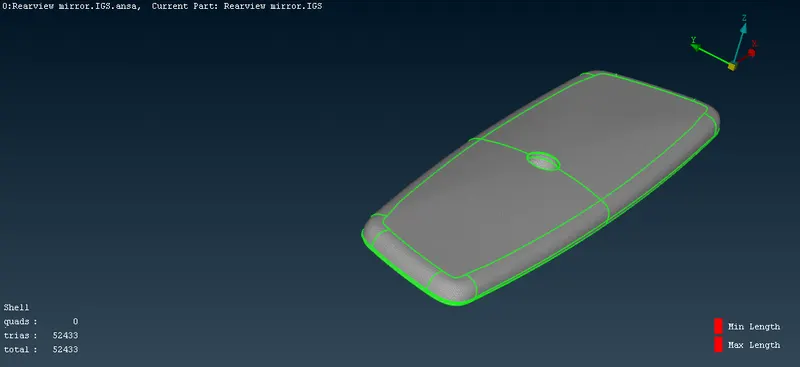
- The same procedure is to be followed for meshing the body. The fillets to be meshed first with spot mesh option and selecting ortho tria.
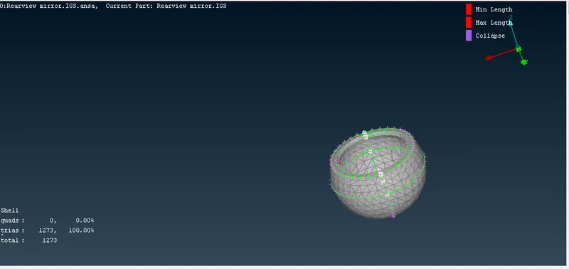
- The inner curved surfaces of the socket have also meshed with Ortho Tria elements. All other curved surfaces are also meshed using Ortho Tria elements while flat surfaces are meshed using Tria elements.
- Now, we work on defeaturing and meshing the Socket component.
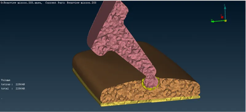
- Defining closed volumes for each component part and deploying an appropriate Solid/ Volume mesh algorithm to get a Tetra-mesh representing the volume of the CAD.
- Now, as all the components have been shell-meshed, we can now generate the Volume-Mesh or Tetra-Mesh for each component one by one.
- For this, we need to first define each component part as a separate closed volume and then use a volume-mesh generating algorithm.
- The volume is defined using Define> Select and select the CAD geometry.By this the Volume Mesh is created.
- This unmeshed volume can be seen in the List volume library under the Volumes tab in the Volume Mesh Module. This unmeshed volume can directly be meshed from this List by right-clicking and selecting Remesh and the appropriate algorithm after that.
- Alternatively, after defining the volume we can directly use an algorithm from the Unstructured Mesh Tab like Tetra Rapid or Tetra FEM.
- For the actual solving of this model, it is necessary to separate the volume and the volume mesh, i.e. make ANSA identify the volume mesh as a FE model.
- This can be done by first switching ON just the Volume and Wire views and switching OFF the FE-Mode and Geometry views. Bounds can also be switched ON for better visibility. After this, we can select the volumes on the graphical window and use Volumes> Release in the Volume Mesh module to release the same.
CONCLUSION
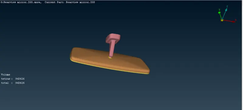
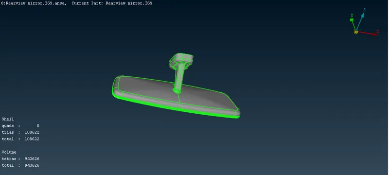
A Volume-mesh or more accurately a Tetra-mesh was generated for the given Rearview Mirror CAD assembly with the given Mesh Parameters and the Quality Criteria. The procedure for the same is explained in detail in this report. Required defeaturing was done before meshing and Quality parameters were checked after the meshing was completed. Finally, the generated volume mesh or the FE model thus generated was then released from the parent CAD model and its volume.
- Learning Outcomes:
- The theoretical knowledge of 3D/ Volume meshing and subsequently Tetra and Hexa meshing was understood before this project was started.
- The differences between Structured and Unstructured Mesh were understood along with its applications and significance.
- The significance of the surface quality of a Volume-meshed model and its coincidence with the original CAD model surfaces was noted.
- The differences in the Tetra Meshing algorithms namely Tetra Rapid and Tetra FEM were understood.
- The concept of Growth Rate in a volume mesh algorithm was understood.
- The meaning and significance of the quality criterion Tet Collapse were understood along with its rectification if any tetra element fails for the same.
- I also learned how and why to release the generated Volume Mesh, Shell Mesh, or simply any FE model from its parent CAD model.