Week - 5 - Modelling Spotwelds
MODELING SPOT-WELD USING BEAM AND SOLID ELEMENTS AND CRASH ANALYSIS
Objective: To create spot-weld Beam and solid beam elements on given steel plate assembly separately. Also, perform the crash analysis for both and compare the output results.
Introduction:
Spot welding is one of the oldest welding processes. It is used in a wide range of industries but notably for the assembly of sheet steel vehicle bodies. This is a type of resistance welding where the spot welds are made at regular intervals on overlapping sheets of metal. Spot welding is primarily used for joining parts that are normally up to 3 mm in thickness.
Step by step Procedure:
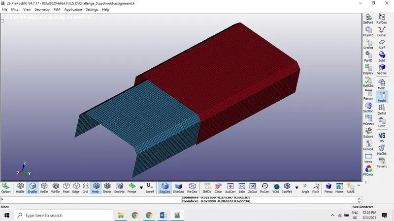
Import the Spot-weld k. file by opening the Ls Pre-Post. We can see the assembly of the spot-weld plates.
Material Card set-up: MAT-024 or MAT_ Piece wise_ linear _ plasticity from the keyword manager
As we can see the image, the model with mesh position using the auto center option so that we can see the image properly. We consider mesh only in the setup so we can delete the solid in the model.
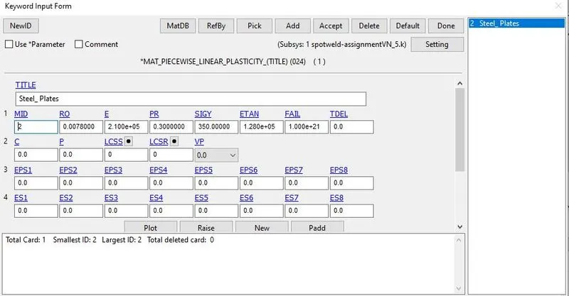
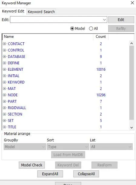
Now open the keyword manger by clicking on the model icon then assign the material by opening the keyword manger, open the MAT file to assign the material property to the model from exiting materials. There are many material type available here but *MAT_024* is the piecewise Linear plasticity which is suitable for robust materials of linear plasticity also suitable for elastoplastic materials. (Strain –rate dependency) Which is suitable for viscoelastic material behavior with arbitrary stress.
Keyword Manger > select MAT> 024 > keyword input form
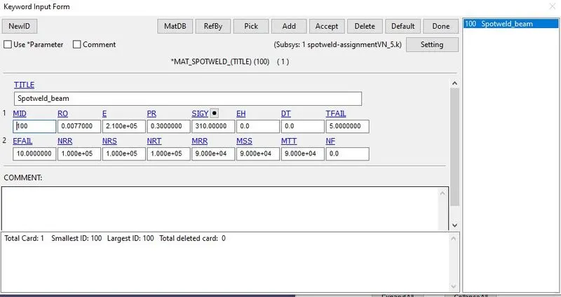
MAT_100 or MAT_SPOTWELD – keyword Manager→
This is Material Type 100. The material model applies to beam element type 9 and to Solid element type 1 the failure models apply to both beam and solid elements.
Part and Section cards:
In this section, the element formulation, integration rule, nodal thicknesses, and cross sectional properties are defined. All section identifiers (SECID’s) defined in this section must be unique; that is, if a number is used as a section ID for a beam element, then this number cannot be used again as a section ID for a solid element. Element formulation 9 and for section shell element formation1 (ELFORM) Section solid.
Keyword manger → Model→ Section→ Beam or Shell
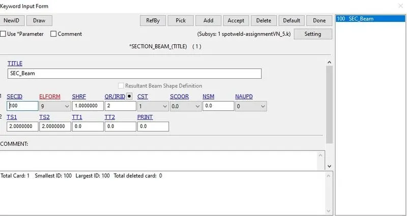
Created FE section shell elements with thickness 2.0mm using LS Dyna keyword manger → Model (All) → Section
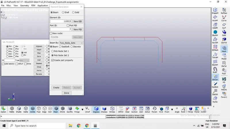
Creating the spot-weld beam elements using clicking Mesh icon in the right side toolbar then open element generation...
Beam→ Beam Type →Two_Node_Set→ select the two nodes from the mesh→ Accept
Model the 5 spot-weld beam elements as per the instruction given.
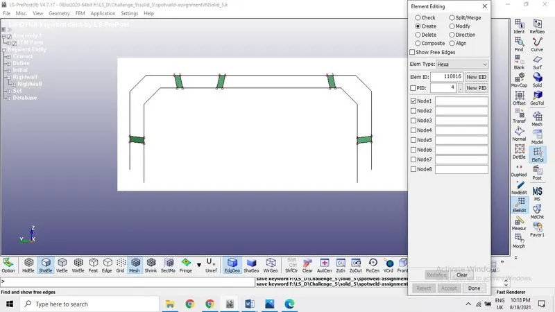
In case of solid element generation, we can use element tool which is more convenient to model the solid spot weld elements of 8-Nodes
EleTool→ EleEdit→ Create → EleType →Hexa→ Select the 8-Node from Top, Bottom parts → Accept
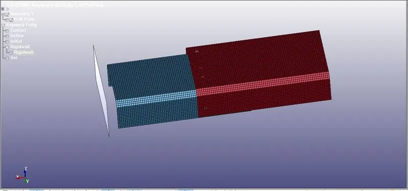
Rigid wall
Rigid wall definitions have been divided into two separate sections, PLANAR and GEOMETRIC. Planar walls can be either stationary or moving in translational motion with mass and initial velocity. The planar wall can be either finite or infinite. Geometric walls can be planar as well as have the geometric shapes, such as rectangular prism, cylindrical prism and sphere.
Add frictional energy calculation for constraint-based rigid walls. Keyword entity→ rigid wall → selecting the option planar or node. After creating the rigid wall move it away from the Steel Plates of distance required using the translation option. Rigid wall is hit by the Steel plates with a velocity of 50 KMPH (13.88 mm/ms.) the distance between Plate and rigid wall is 20 mm here.
Initial velocity of the plate Assembly
The initial velocity card set up here with 13.8 mm/ms which is in the direction rigid wall about X-direction here. And also set the node set ID of the part
Control Termination: To stop the calculation at particular time
The keyword *TERMINATION provides an alternative way of stopping the calculation before the termination time is reached. The termination time is specified on the *CONTROL_TERMINATION input and will terminate the calculation whether or not the options available in this section are active. Time is given here 10 ms.
Contact card and Set:
Most of the control contacts are single surface contacts for crash and impact type. A self-established contact in our model as there only single surface contact card. We have one surface it automatically recognize the surface elements.
We need to create node set and set part before we create contact card. Then
SET_NODES - Create Entity→ set data → Create → pick nodes → Apply
SET_PART - Create Entity→ set data → Create → pick or select the part → Apply
Here spot-weld beam elements as slave set ID and master set ID as part set ID
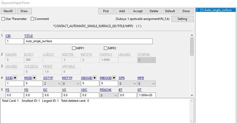
In this case slave set is Node set and remaining all the parts considered as master set ID
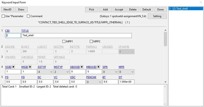
Model checking
Energy Plot for Beam and solid spot-weld.
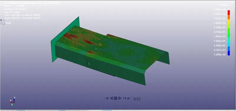
The min stress is at -128.36 at element# 8281, Maximum at 238.751 at element # 106572
Von Mises stress is a value used to determine if a given material will yield or fracture. It is mostly used for ductile materials, such as metals. The von Mises yield criterion states that if the von Mises stress of a material under load is equal or greater than the yield limit of the same material under simple tension then the material will yield. In both the cases simulation time is 3.5 ms approximately, the spot-weld fails exactly the less than the half time the termination time given
Animation file for spot-weld Solid beam element.
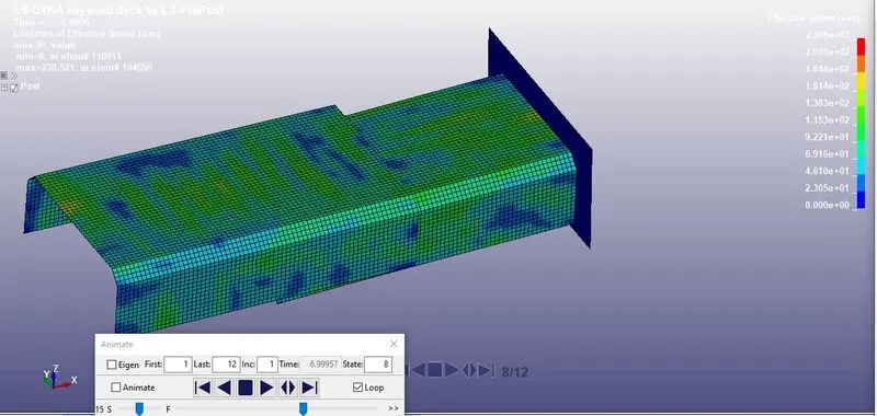
The min stress is at 0 at element# 110011, Maximum at 230.521 at element # 104690.
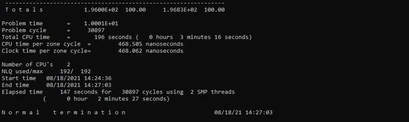
Here we can see the normal termination. Termination time given 10 ms.
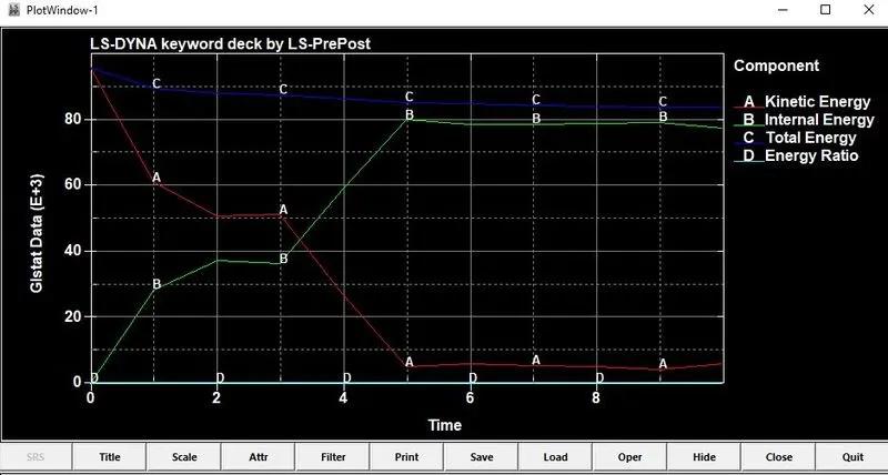
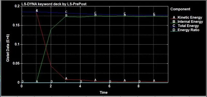
Energy plot graph for both BEAM ELEMENT and SOLID ELEMENT
Both the cases after crashing the wall the kinetic energy decreases then the internal energy increase due to energy absorbed by the rigid wall. This is positive trend we can observe both the cases here.
Spot-weld Solid beam
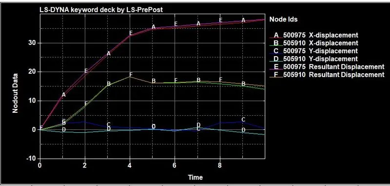
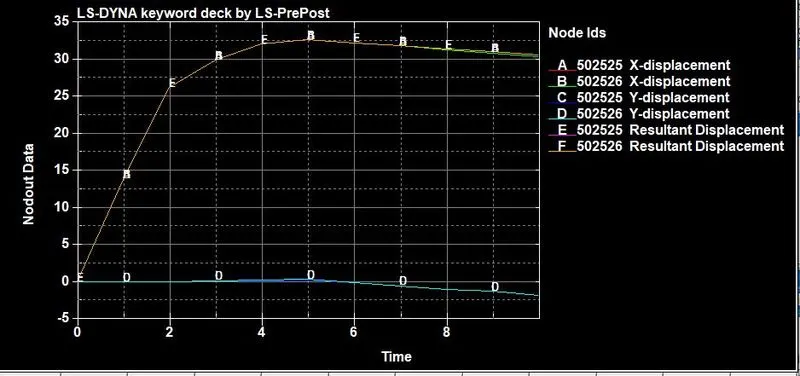
NODOUT PLOT
We can see the trend X-displacement is more compare to Y- displacement due to the velocity of the plate assembly is in positive X-direction and both the nodes are mentioned in the History node in the Database.
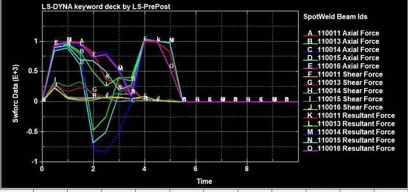
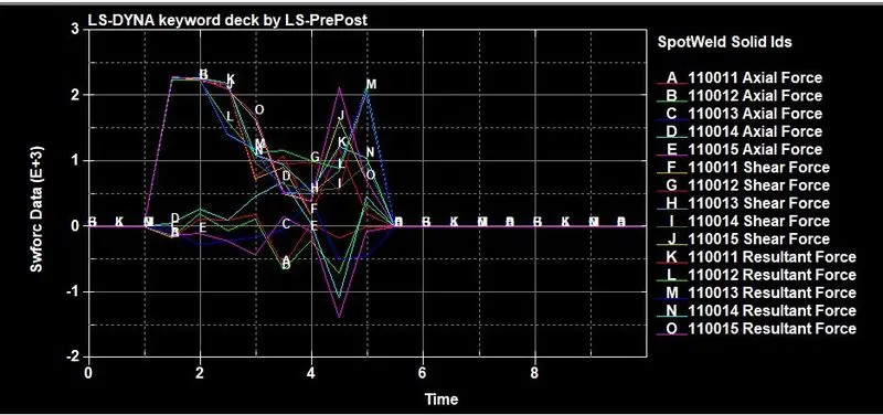
Beam and solid element force resultants for MAT_SPOTWELD are written to the spot weld force file, swforc, and the file for element stresses and resultants for designated elements, elout.
Comparing the Axial and Shear force of both elements.
Conclusion
- Simulation keyword preparation is done according to the given requirement.
- Animation and the simulation using LS-Run without any error termination
- Simulation is done for both beam and Solid element and analyzed the results.
- Plotted graphs for output energies of spot-weld assembly.