Week - 5 - Modelling Spotwelds
AIM: To perform the simulation of crashes using beam and solid spot welds and compare the outputs.
KEYWORDS: Contact energy, Hourglass, Contact, Boundary condition, Materials, Section, Initial Velocity, etc.,
SOFTWARE: LS-Dyna
OBJECTIVE:
- For the given meshed model check for the number of parts and rename accordingly.
- Creating suitable keywords like Material (Rigid & M24), Contact (Surface - Surface), Boundary condition (Rigid material), Section (Shell & Solid) & Control cards.
- Initial Velocity is given for the mobile part as 10 m/s.
- After creating the keywords, check for the model and save the keyword file.
- Run the keyword file in LS-run and simulate.
- In the simulation, get the contour plot of Von-Moses stress and Effective strain.
- Plot all the energies (Kinetic, Internal, Total, Hourglass & Sliding) vs. Time (s).
- The total termination time is given as 5ms.
INTRODUCTION:
Time Scaling. The inertias of the spot welds are scaled during the first timestep so that their stable time step size is Δ𝑡. A strong compressive load on the spot weld at a later time may reduce the length of the spot weld so that stable time step size drops below Δ𝑡. If the value of Δ𝑡 is zero, mass scaling is not performed, and the spot welds will probably limit the time step size. Under most circumstances, the inertias of the spot welds are small enough that scaling them will have a negligible effect on the structural response and the use of this option is encouraged.
SpotWeld Failure Criteria:
Failure of the spot welds occurs when:
(∣𝑓𝑛∣ 𝑆𝑛)𝑛 + (∣𝑓𝑠∣ 𝑆𝑠)𝑚 ≥ 1,
where 𝑓𝑛 and 𝑓𝑠 are the normal and shear interface forces. Component 𝑓𝑛 is nonzero for tensile values only. When SN and SM are specified by curve IDs, failure of the spot welds occurs when:
( ∣𝑓𝑛∣ 𝑆𝑛(𝑇))𝑛 + ( ∣𝑓𝑠∣ 𝑆𝑠(𝑇))𝑚 ≥ 1,
where 𝑇 is the nodal temperature.
Importing the Model:
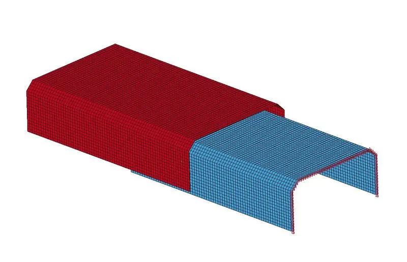
We first open the LS Prepost software and import the keyword file (.k file).
 +
+
Assigning Section:
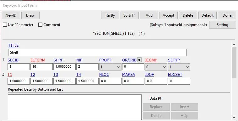
Since the Sheet Metals are meshed using 2d elements we will define them with the SECTION_SHELL card. We also parallelly assign section properties i.e. 1.5 mm thickness to the sheet metal plates as well.
Here,
- SECID: Section ID. SECID is referenced on the *PART card. A unique Number or label must be specified.
- ELFORM: Element formulation options.=16 Fully integrated shell element (very fast)
- SHRF: Shear correction factor which scales the transverse shear stress.= 1
- NIP: Number of through-thickness integration points = 2
- T1: Shell thickness =1.5 mm
Assigning Material:
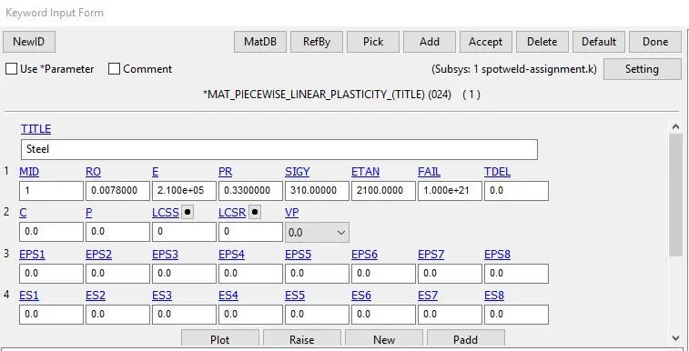
We are supposed to Create Two material cards one for the sheet metal and the other for spot weld. We are using MAT_ELASTIC card for Sheet metal using Steel Properties and the unit system followed for the unit consistency is gm-mm-ms.
Here,
- MID: Material identification. A unique number or label not exceeding 8 Characters must be specified.
- RO: Mass density = 0.00785 gm/mm3
- E: Young’s modulus = 2.10 e+05 N/mm2
- PR: Poisson’s ratio=0.3
Assigning Materials and Sections to Parts:
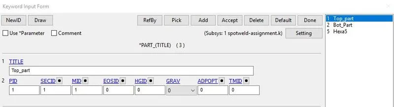
We specify the respective Material and Section ID to the bottom and top sheet metal part IDs.
Boundary Conditions:
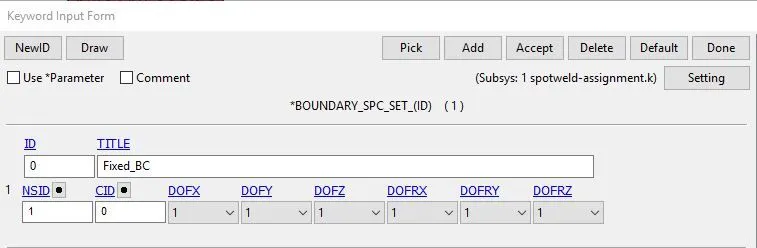
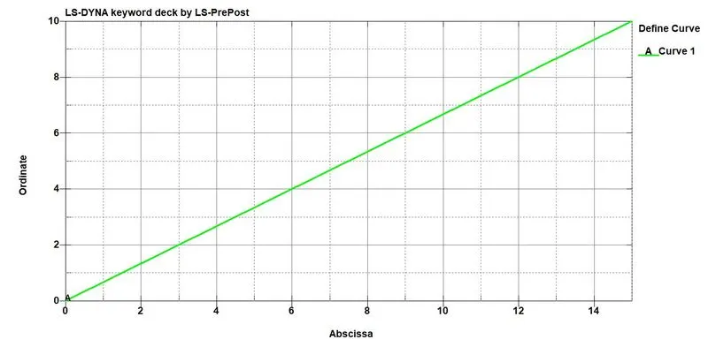
The next step is to define a velocity or Displacement curve for prescribed boundary conditions and assigned it to each node of a second part the first part has to be fixed in all direction, under Entity Creation >Boundary condition>Prescribed motion. 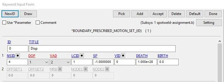
Control Cards:
The spot-weld can be modeled as beam and solid elements by using the following techniques,
- To represent as a beam element, we use *CONTROL_TIED_SHELL_EDGE_TO_SURFACE card
- To represent as a solid element, we use *CONTROL_SPOTWELD card
Spot-weld modeled using Beam element:
The spot weld modeled using beam element is created by selecting the Mesh > Element Generation > Beam > Give Part ID > Select Beam by Two_Node_Sets > Pick Node set 1 & 2 (pick the desired nodes from the bottom and top sheet metal) > Create > Accept > Done. Now this beam element acts as a spot weld.
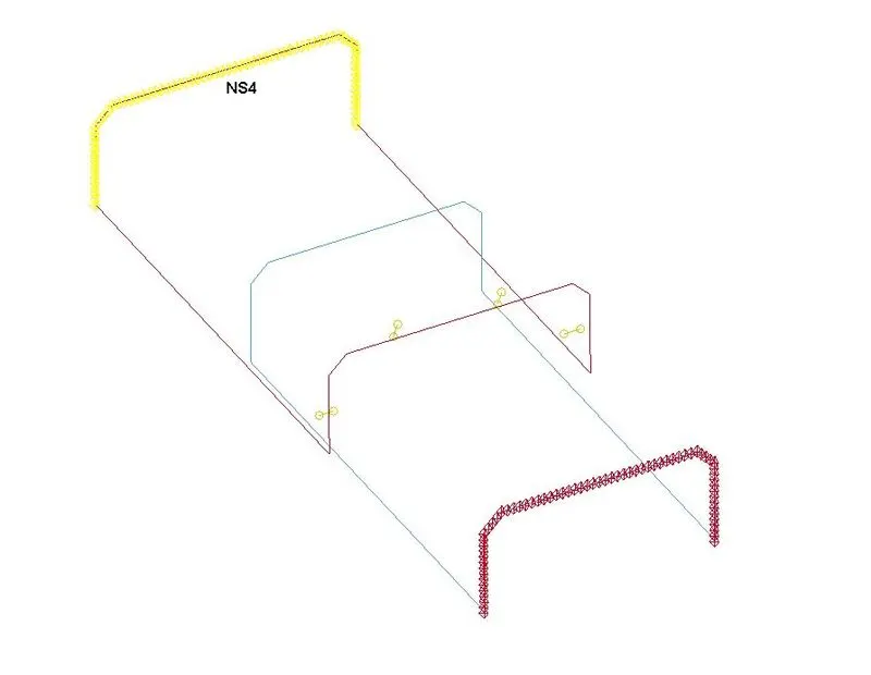
Here the fact is that automatically a Section card (*SECTION_BEAM) and the Material card (*MAT_CABLE_DISCRETE_BEAM) are created and we need to delete these cards and assign our required material and section cards.
Defining the Material card for Beam Element:
For the beam element, the material card is assigned as the *MAT_100 that is especially for the spot weld material. The values are assigned and here we are taking a time-dependent failure concept rather than the force-dependent failure concepts like Effective plastic strain, maximum axial stress, maximum shear stress, Force resultant, Torsional moment resultant, Moment resultant. So to keep this problem as a Time-dependent failure we given other failure terms as a higher value.
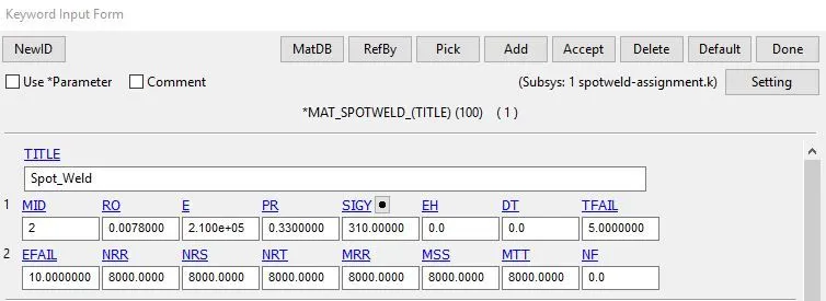
Here,
- MID: Material identification. A unique number or label not exceeding 8 characters must be specified.
- RO: Mass density
- E: Young’s modulus.
- .PR: Poisson’s ratio
- SIGY: Initial yield stress
- TFAIL: Failure time if nonzero. If zero this option is ignored.
- EFAIL: Effective plastic strain in weld material at failure
- NRR: Axial force resultant 𝑁𝑟𝑟 at failure.
- NRS: Shear Force resultant 𝑁𝑟𝑠𝐹 at failure
- NRT: Force resultant 𝑁𝑟𝑡𝐹 at failure
- MRR: Torsional moment resultant 𝑀𝑟𝑟𝐹 at failure.
- MSS: Moment resultant 𝑀𝑠𝑠𝐹 at failure
- MTT: Moment resultant 𝑀𝑡𝑡𝐹 at failure.
Defining the Section card for Beam Element:
For the beam element, the section property is assigned by using the *SECTION_BEAM card. It is important to assign element formulation (ELFORM) as 9 because the *MAT_100 spot weld material model only applies for ELFORM 9 formulation in the case of the beam element. The cross-section type is selected as tubular since the default cross-section(rectangular) gives zero cross-section area during the simulation and the beam thickness at both ends is given as 3mm.
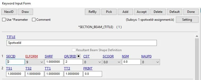
Here,
- SECID: Section ID. SECID is referenced on the *PART card. A unique Number or label must be specified.
- ELFORM: Element formulation options.= 9 spotweld beam
- SHRF: Shear correction factor which scales the transverse shear stress.= 1
- QR/IRID: Quadrature rule or rule number for the user-defined rule for integrated beams.
Assigning Materials and Sections to Parts:
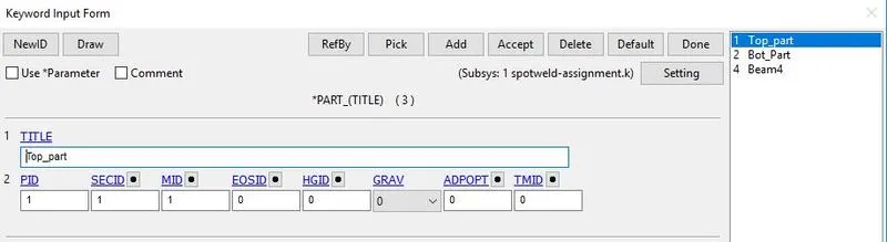
We specify the respective Material and Section ID to the spotweld IDs.
Defining the Contact card for Beam Element:
Here for the beam element, the contact type to be used is *CONTACT_TIED_SHELL_EDGE_TO_SURFACE card and the master set id will be Part id and the Slave set id will be nodes of beam weld element. For defining the Slave set select beam nodes to create the set and the steps are mentioned below,
Entity Create > SetData > *SET_NODE > Pick the nodes > Apply.
For defining the Master set select both the metal sheet parts and the steps is mentioned below,
Entity Create > SetData > *SET_PART > Pick the part > Apply.
So assign both the slave-set and the master-set as created by the above technique to the contact card. *CONTACT_TIED_SHELL_EDGE_TO_SURFACE card.
Slave-type - Node set ID
Master-type - Part set ID
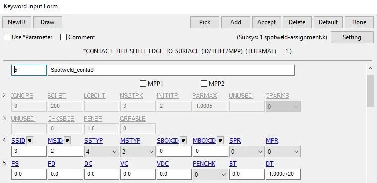
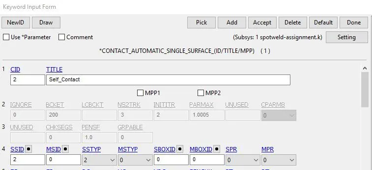
Also, we need to create an Automatic_single_surface contact card for the parts to ensure that after the spot weld breaks the parts come to each other they shouldn't penetrate. Here the parts-sets are the slaves.
Spot-weld modeled using Solid element:
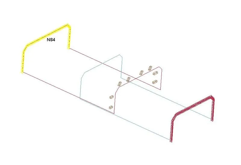
The spotweld modeled using solid element is created by selecting the Element Tools > Element Editing > Create > Type - Hexa > Pick four desired nodes from the bottom and top sheet metal > Accept > Done. Now this solid element act as a spot weld.
Defining the Material card for Beam Element:
For the beam element, the material card is assigned as the *MAT_100 that is especially for the spot weld material. The values are assigned and here we are taking a time-dependent failure concept rather than the force-dependent failure concepts like Effective plastic strain, maximum axial stress, maximum shear stress, Force resultant, Torsional moment resultant, Moment resultant. So to keep this problem as a Time-dependent failure we given other failure terms as a higher value.
Here,
- MID: Material identification. A unique number or label not exceeding 8 characters must be specified.
- RO: Mass density
- E: Young’s modulus.
- .PR: Poisson’s ratio
- SIGY: Initial yield stress
- TFAIL: Failure time if nonzero. If zero this option is ignored.
- EFAIL: Effective plastic strain in weld material at failure
- NRR: Axial force resultant 𝑁𝑟𝑟 at failure.
- NRS: Shear Force resultant 𝑁𝑟𝑠𝐹 at failure
- NRT: Force resultant 𝑁𝑟𝑡𝐹 at failure
- MRR: Torsional moment resultant 𝑀𝑟𝑟𝐹 at failure.
- MSS: Moment resultant 𝑀𝑠𝑠𝐹 at failure
- MTT: Moment resultant 𝑀𝑡𝑡𝐹 at failure.
Defining the Section card for Solid Element:
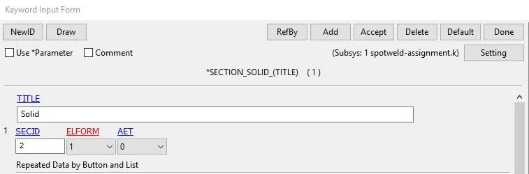
For the solid element, the section property is assigned by using the *SECTION_SOLID card. It is important to assign element formulation (ELFORM) as 1 because the *MAT_100 spot weld material model only applies for ELFORM 1 formulation in the case of the solid element.
Here,
- SECID: Section ID. SECID is referenced on the *PART card. A unique Number or label must be specified.
- ELFORM: Element formulation options.= 1 solid element.
Assigning Materials and Sections to Parts:
We specify the respective Material and Section ID to the spotweld Hexa element IDs.
Defining the Contact card for Solid Element:
20) Here for the solid element, the contact type to be used is the *CONTACT_SPOTWELD card and the master set id will be Part id, and the Slave set id will be nodes of solid weld element.
For defining the Slave set select solid nodes to create the set and the steps are mentioned below,
Entity Create > SetData > *SET_NODE > Pick the nodes > Apply.
For defining the Master set select both the metal sheet parts and the steps is mentioned below,
Entity Create > SetData > *SET_PART > Pick the part > Apply.
So assign both the slave-set and the master-set as created by the above technique to the contact card. *CONTACT_SPOTWELD card.
Slave-type - Node set ID
Master-type - Part set ID
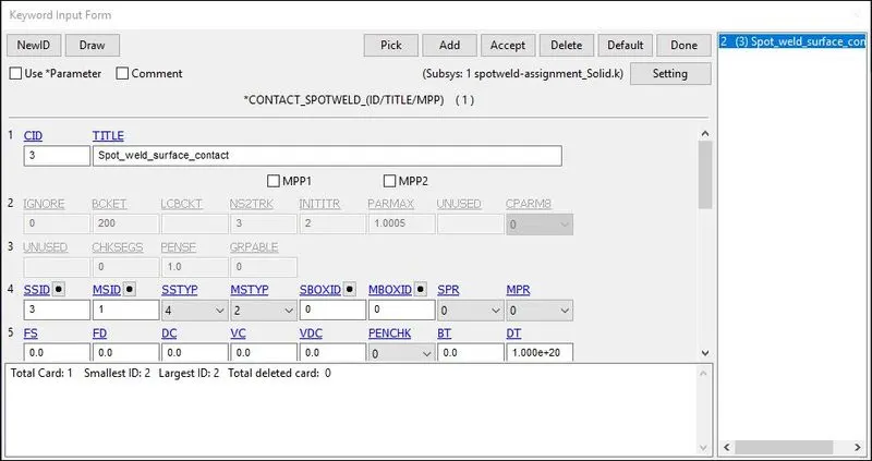
Also we need to create an Automatic_single_surface contact card for the parts to ensure that after the spot weld breaks the parts come to each other they shouldn't penetrate. Here the parts-sets are the slaves.
Control Cards:
Control_Termination is defined at what time the simulation ends or the end time of the simulation and it is set to 5 ms.
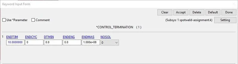
Here,
ENDTIM: It is the time at which the simulation ends.
Control_Energy provides controls for energy dissipation options.
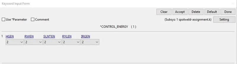
Here,
- HGEN: Hourglass energy calculation option. Is set to 2 In Which hourglass energy is computed and included in the energy balance.
- RWEN: Rigid wall energy dissipation option: Is set to 2 in Which energy dissipation is computed and included in the energy balance.
- SLNTEN: Sliding interface energy dissipation option Since the Contact is Defined it is set to 2 so that energy dissipation is computed and included in the energy balance.
Database Creation:
24) BINARY_D3PLOT is defined as the frequency at which the animation file is to be created and is set to 0.5 ms.
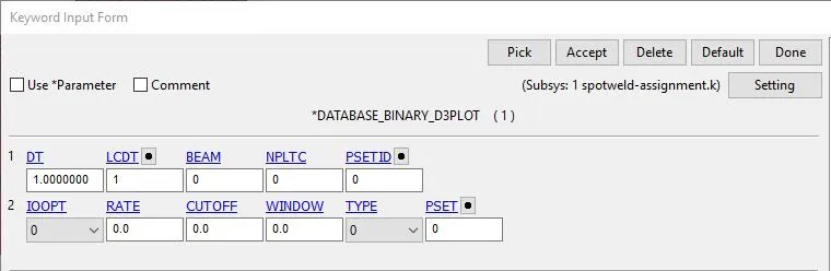
Here,
DT: Time-frequency at which the animation files should be printed.
Time History:
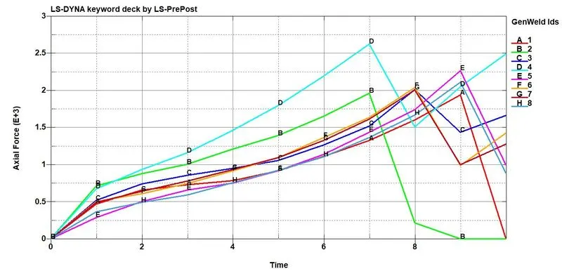
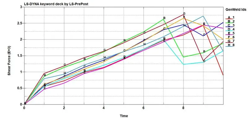
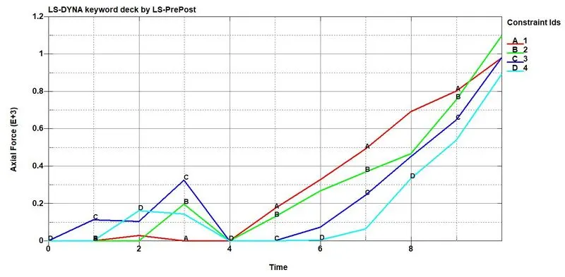
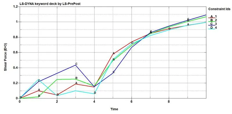
We take history for beam and solid elements for measuring axial and shear forces on the beam and solid elements
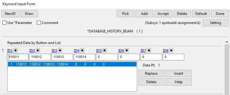
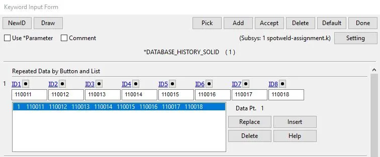
DATABASE:
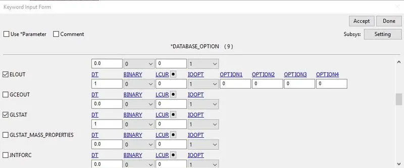
ASCII_option keyword is the output request in ASCII format, The following keywords are Activated.
- ELOUT: Element Data
- GLSTAT: Global Data
- MATSUM: Material Energies
- SWFORC: Spotweld Nodal Constraint Reaction Forces
- NODOUT: Nodal point data
- SECFORC: Cross-section forces
Keywords with Model Check:
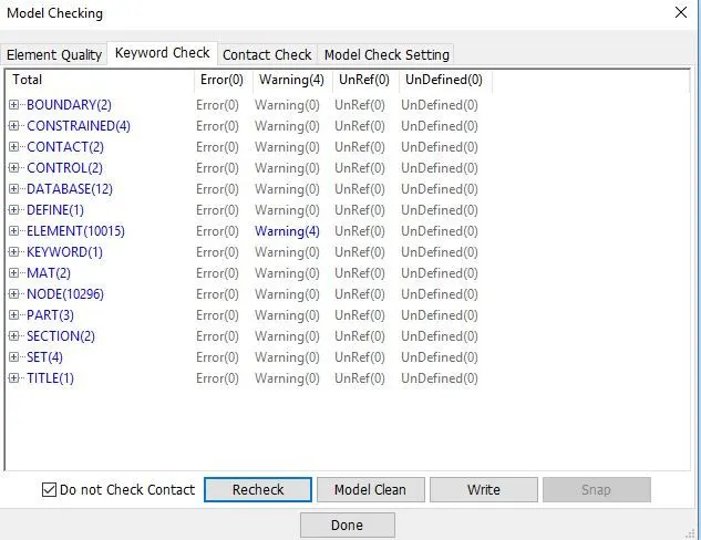
Finally, we have set up the simulation model for both cases and have a final look at our keyword manager which contains all the necessary parameters for running the simulation.
Results and Discussion:
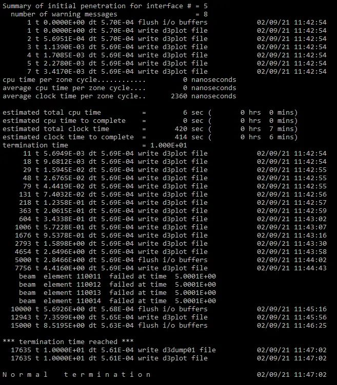
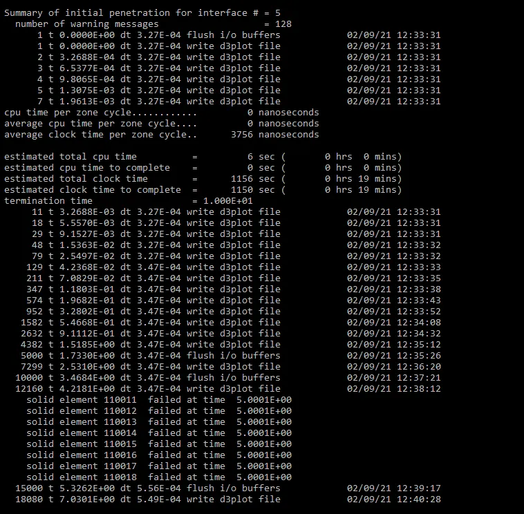
1) We save the LS Dyna keyword file in a different folder and we go to the LS-Run Manager and run the simulation by importing the LS Dyna keyword file. The simulation finishes successfully with a normal termination. We then go to lsrun.out file and open it with a text editor to see the time taken for both beam and solid spotweld models to complete the simulation.
For Beam:
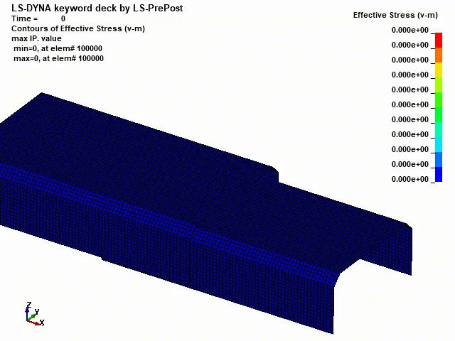
For Solid:
Contour Animation:
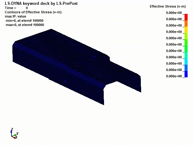
The von Mises yield criterion states that if the von Mises stress of a material under load is equal or greater than the yield limit of the same material under simple tension then the material will yield. In both the simulation the component acts under shear and axial forces in the simulation, the spotweld fails, exactly half the termination time ie, 5ms. There is no abnormal behavior of elements during the simulation since the element's materials are defined using the elastic property. After the spot weld fails we can see that the top and bottom parts come into contact and causing the stress at the contact area and which is shown in the below contour as a red-colored region.
For Beam:
For Solid:
Output Results:
Axial & Shear forces for Solid Elements:
Axial & Shear forces for Beam Elements:
Conclusion:
1) The spot welds are modeled using Beam and Solid elements for the same component.
2) The material card and all other keywords are properly defined for the simulation.
3) The simulation carried out with time-dependent failure and the spot weld is failed at half of the termination time.
4) The plot results and contour diagrams are compared.