Week - 5 - Modelling Spotwelds
Aim:
To model spotweld for the given assembly using beam and solids and to analyse the differences in the crash test result
Explanation:
Spotwelds can be modelled using 4 methods
- Beam element and Tied contact
- Solid element and spotweld contact
- Using constrained spotweld
- Using constrained generalized
We will be using the first 2 methods and analyse the differences in the result
The given model has the following keywords
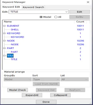
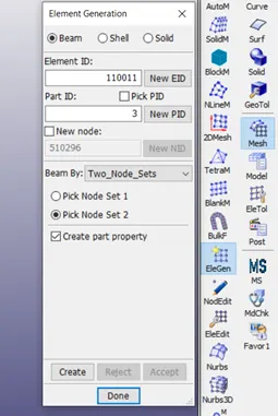
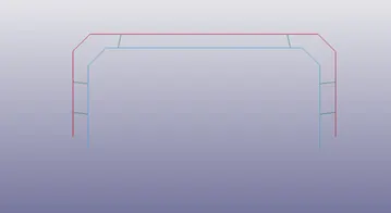
We need to create beam elements and solid elements in the model for the spotweld
Mesh->EleGen->Beam/Solid
Material model:
Two material cards are required. One for sheet metal and other for spotweld
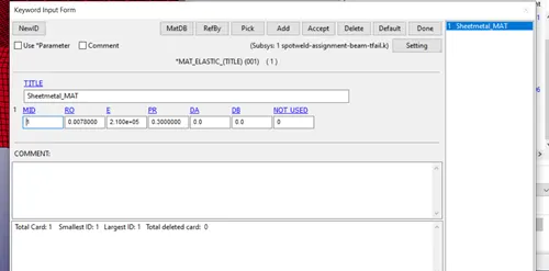
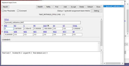
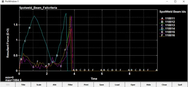
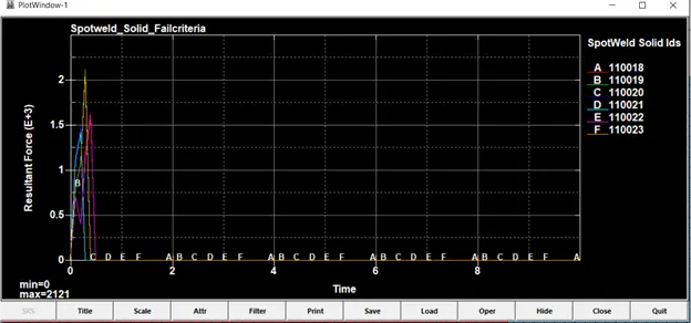
This is the material data used to get failure forces NRR, NRS and NRT. This is done by specifying value for TFAIL (half the termination time). So, the model fails at the middle of the simulation and the forces at that time of failure can be used to build the material failure data for both the models.
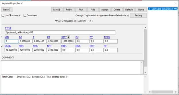
This is the failure material data obtained from the trial run using TFAIL. We can use the value at the time of failure for axial, shear and resultant (NRR, NRS and NRT) and can omit TFAIL.
Section:
We need to create two sections. One for sheetmetal and one for spotweld
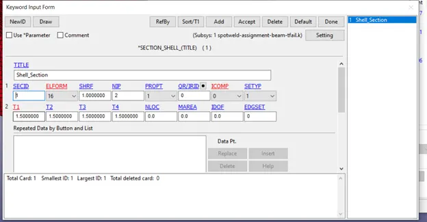
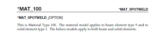
While creating section for spotweld Beam, only Type 9 should be used. Likewise, for solids, only Type 1 should be used for MAT_Spotweld material.
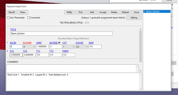
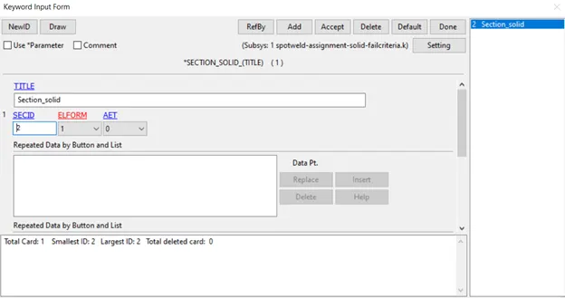
Now assign material and section to respective parts
Boundary Creation:
Create 2 nodesets with the far end nodes of top and bottom part. .
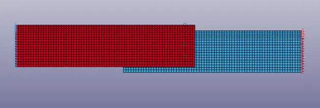
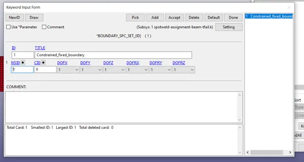
and create Boundary SPC Set to fix all DOF on one end
Create Boundary Prescribed motion set on another end
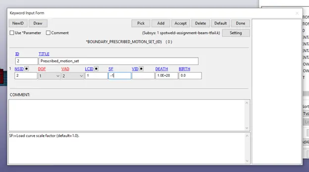
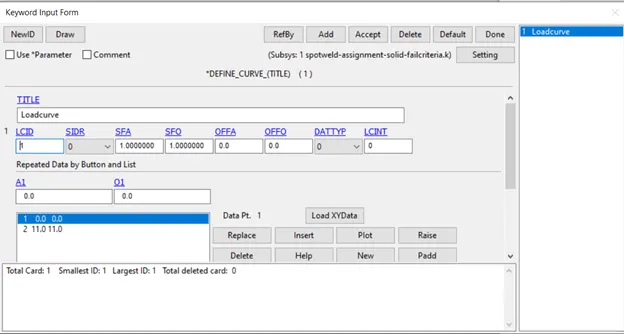
We can also use LCID and define a curve to ramp up the speed from 0 rather than having a constant speed from start.
Contact Creation:
We need to create 2 contacts. One for Sheetmetal top and bottom part interaction (Automatic Single Surface)
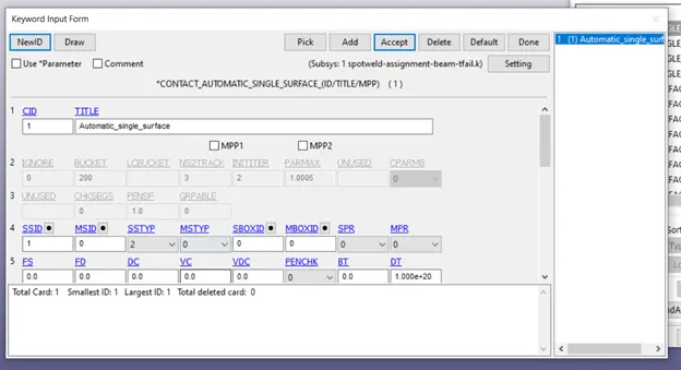
and another for spotweld. Contact for Spotweld can be created using
- Contact Tied shell Edge to Surface
- Contact Spotweld
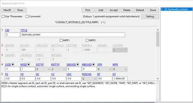
We will use the Contact Tied shell Edge to surface here with beam nodes as slaves and sheetmetal parts as master.
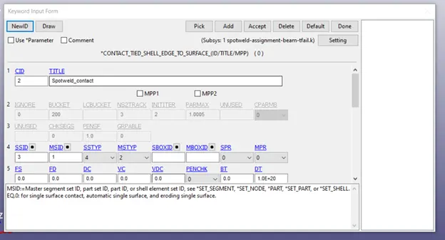
Likewise for solid spotweld, we will use CONTACT_SPOTWELD with solids spotwelds as slave and all shell elements as master.
Control cards:
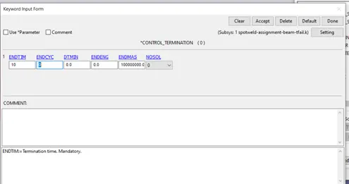
Termination time is given as 10ms
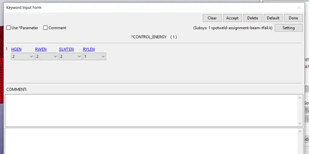
HGEN, RWEN and SLNTEN are activated in control energy
Database cards:
ASCII option cards namely ELOUT, GLSTAT, MATSUM, NODOUT, RCFORC, RWFORC, SECFORC, SLEOUT, SWFORC are selected with 0.01 as DT
Binary D3Plot is used with 0.5 DT
Cross section plane Create Entity -> Database -> Cross Section Plane or Cross section set. Cross section set needs a nodeset and a shell set attached to those nodes.
History node Create Entity -> Database -> History -> Node. Select a node in the bottom part
History shell Create Entity -> Database -> History -> Shell. Select a shell in the bottom part
POST PROCESSESSING
Cross sectional forces at the centre of the crashbox
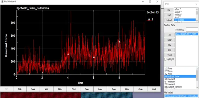
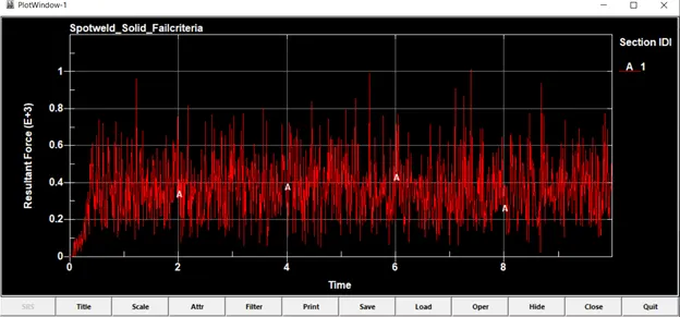
This is the force acting on the cross section of the bottom part which will be travelling across the entire length of the part. This force is generated due to the pulling action on one end of the part and is responsible for the spotweld breakage. The force is resisted by the spotweld and the resultant force (pulling force and spotweld reaction force) which is a non-zero value makes the part move in one direction. When the spotweld breaks, resultant spikes as there is no spotweld reaction force.
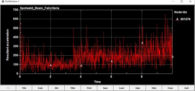
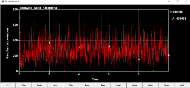
Acceleration plot of a node at the middle of the crashbox
Once the spotweld breaks (around 4ms in beam and around 0.4ms in solid spotweld) the vibration in the shell parts amplify which is logical considering small shell thickness.
Plot of energies
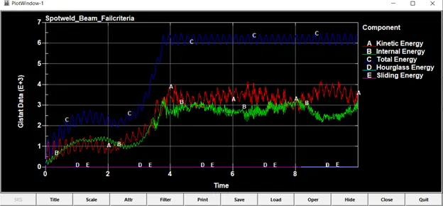
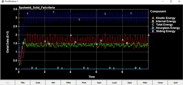
Both Hourglass and Sliding energy are minimum in both the cases. Both internal energy and kinetic energy increases till the point of spotweld breakage (around 4ms in beam and around 0.4ms in solid spotweld) and then oscillates about a constant value. Oscillation in energies is due the sides of the shell parts which move in and out of phase, creating oscillations.
Directional stress and strains
The element-shell is selected near the spotweld for plotting directional stresses and strains.
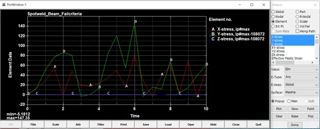
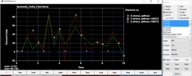
Z stress is zero in both the cases.
|
Beam |
Solid |
|
|
X stress max |
80.6 |
82.8 |
|
Y stress max |
147.35 |
85.7 |
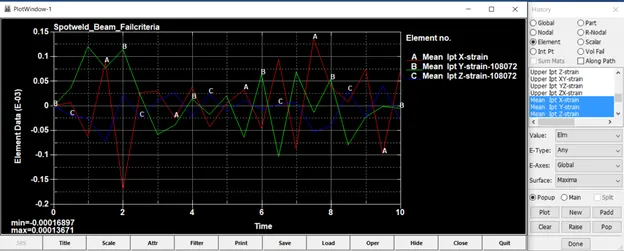
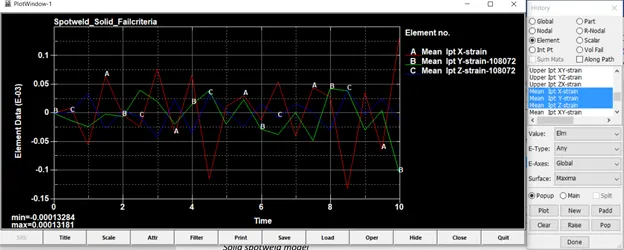
|
Beam |
Solid |
|
|
X Strain max |
-0.000169 |
-0.000133 |
|
Y Strain max |
0.0000121 |
-0.000105 |
|
Z Strain max |
-0.0000715 |
-0.0000421 |