Week - 5 - Modelling Spotwelds
OBJECTIVE:
- To model spotwelds for the given assembly and to perform a crash test.
- To understand the failure behaviour of the spotwelds modelled using beam and solid elements.
- To compare the axial and shear force among beam and solid elements.
- CASE 1: Spotwelds using beam elements.
- CASE 2: Spotwelds using solid elements.
GIVEN MODEL:
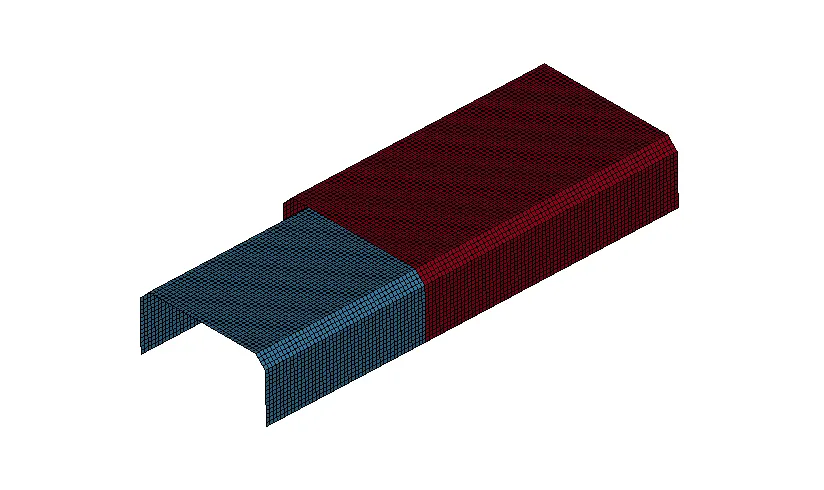
UNIT SYSTEM USED: gm mm ms
INITIAL AND BOUNDARY CONDITIONS:
- The initial velocity of the assembly is 50kmph.
- The rigid wall is 15mm away from the assembly.
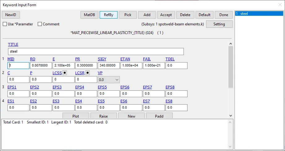
- Steel material data is used for modelling the shell and spotweld elements.
- The simulation time is 2.5ms.
- The number of spotwelds used for case 1 and 2 is four.
MATERIAL PROPERTIES OF THE SHELL ELEMENTS:
CASE 1: SPOTWELDS USING BEAM ELEMENTS.
For spotwelds are modeled using beam elements.
Steel material data is used for the spotweld-beam elements.
Element formulation is set to ELFORM=9 for beam elements and ELFORM=16 for shell elements.
The thickness defined for the beam element is 3mm and 1.2mm for the shell element.
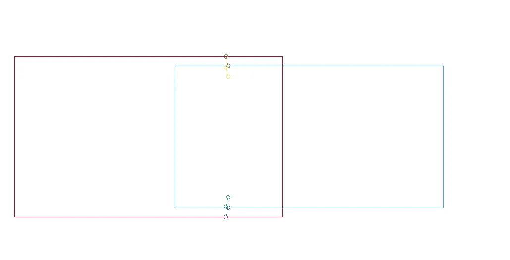
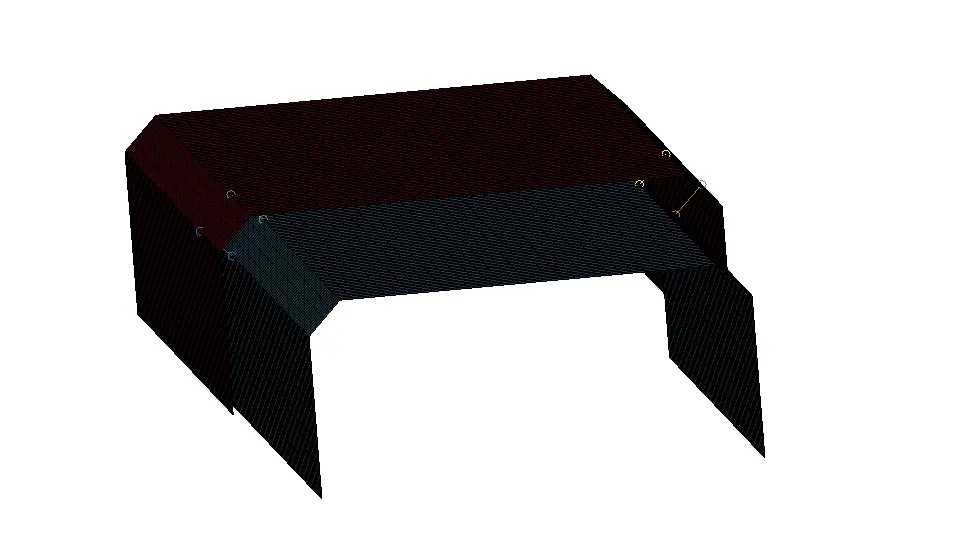
BEAM ELEMENTS:
There are totally 4 beam elements modeled for the analysis:
MATERIAL PROPERTIES OF THE BEAM ELEMENTS:
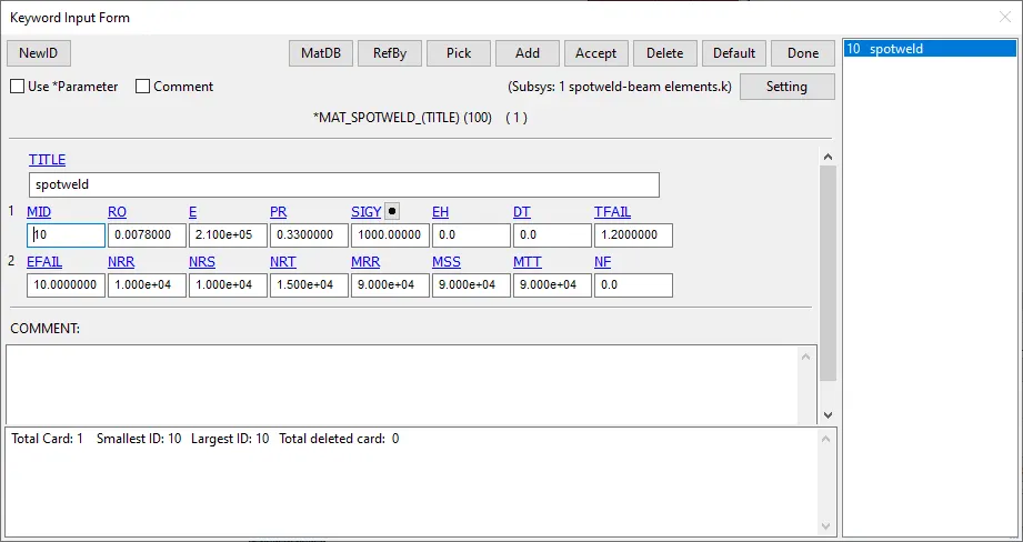
RESULTS:
Animation of the spotweld failure: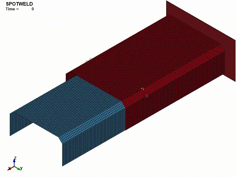
ENERGIES PLOT:
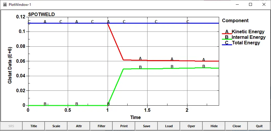
As expected the internal energy increased and the kinetic energy dropped during the impact.
ACCELERATION IN X DIRECTION:
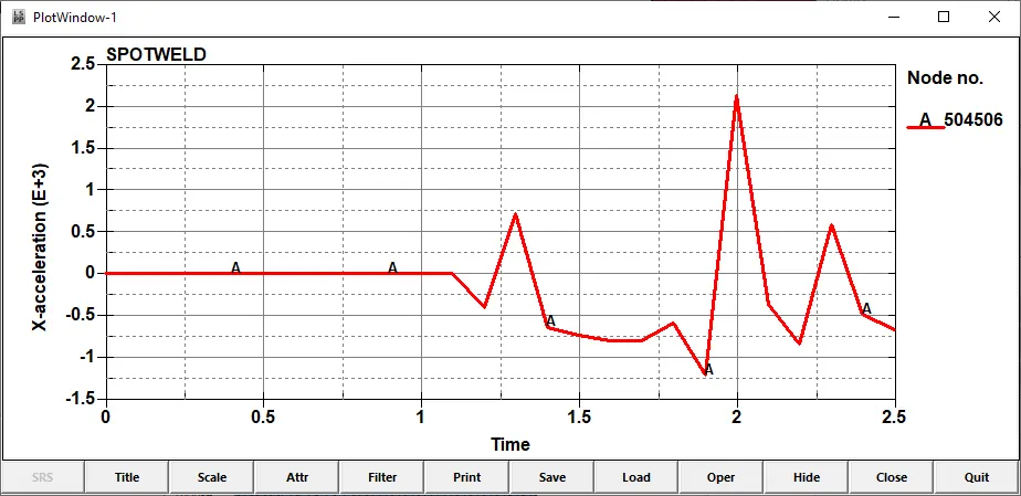
The maximum value for acceleration in x direction is 2200 mm/ms^2.
AXIAL FORCE ON THE WELDS:
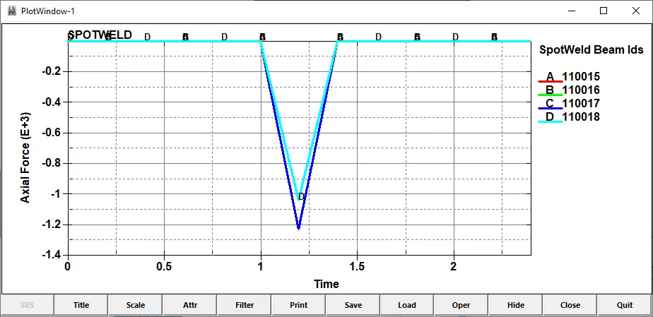
From the plot, it is clear that the spotwelds failed as soon as the collision impact took place.
The negative value of the axial force indicates compressive forces. Modelling the spotwelds in an inclined manner can result in positive value of axial force.
All the spotwelds failed at the same time.
The maximum axial force is around 1250N.
SHEAR FORCE
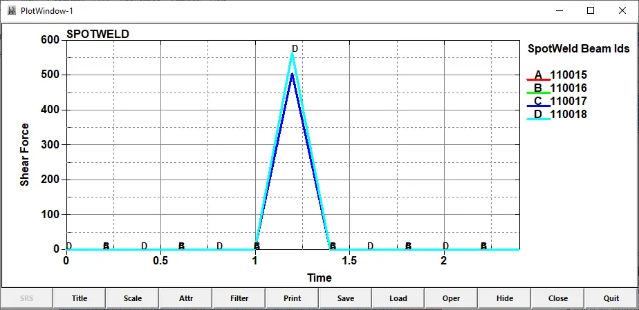
Since the spotwelds are modelled in a straight line, the shear forces are almost same.
The maximum shear force is around 560N.
RESULTANT FORCE:
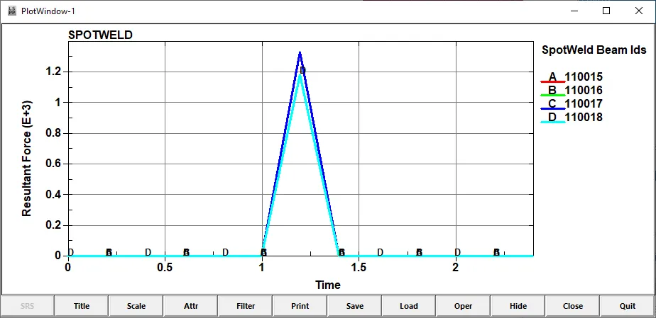
The maximum value for the resultant force is around 1200N.
CASE 2: Spotwelds using Solid Elements.
MODELLING SOLID ELEMENTS:
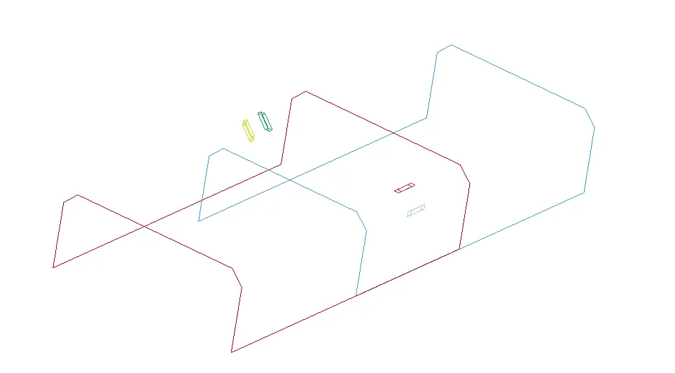
There are totally 4 solid spotweld elements modeled for the analysis:
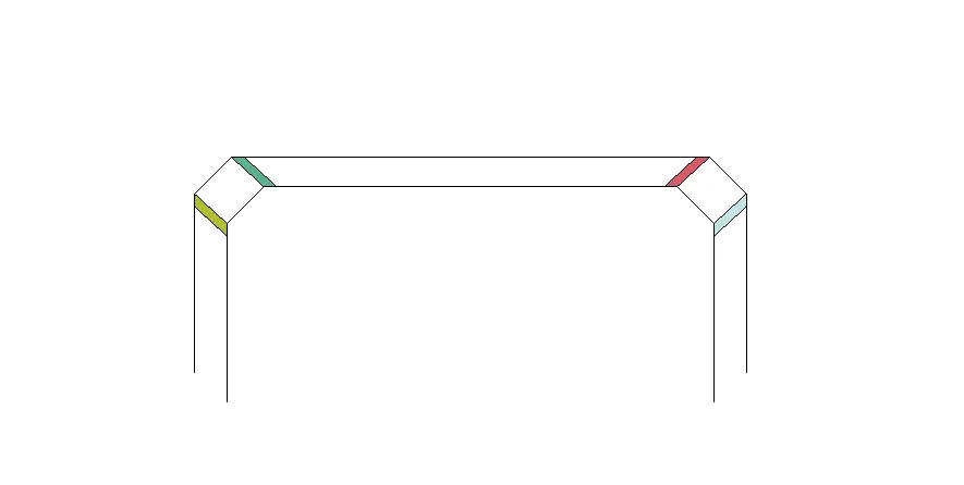
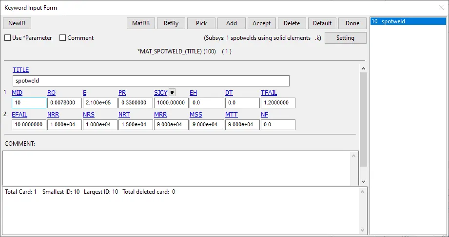
MATERIAL PROPERTIES OF THE SOLID SPOTWELD ELEMENTS:
RESULTS:
Animation of the spotweld failure: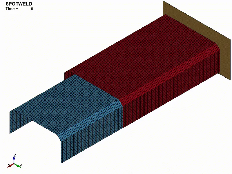
ENERGIES PLOT:
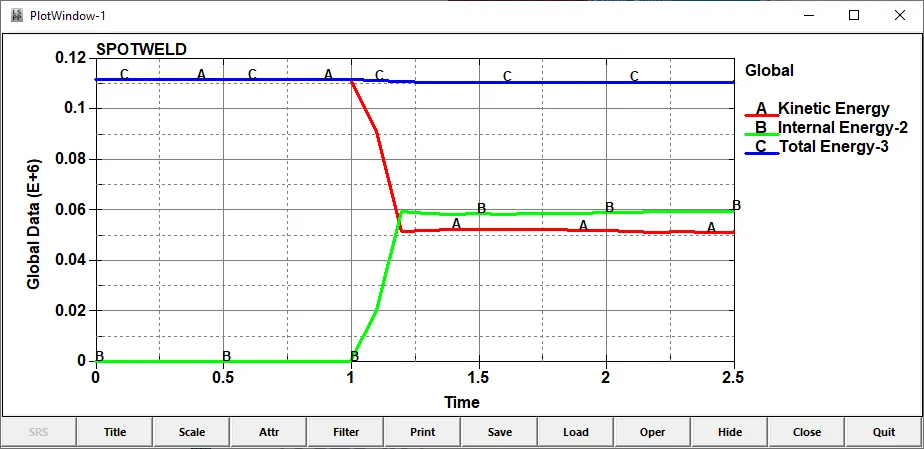
The value of internal energy is little higher than that of beam elements. More energy is absorbed by the solid elements.
ACCELERATION IN X DIRECTION:
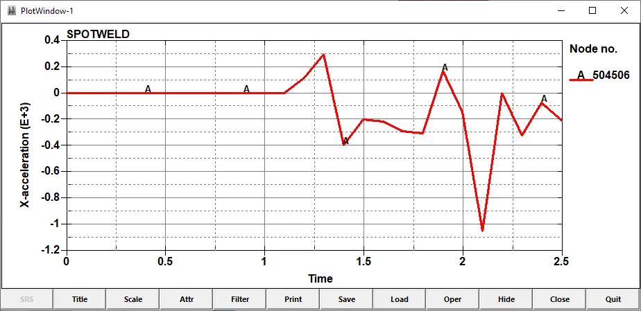
The maximum value of x acceleration is -1000mm/ms^2.
AXIAL FORCE ON THE WELDS:
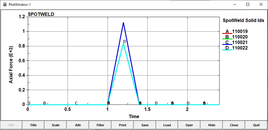
The maximum value of axial force is 1100N, which is slightly lesser than that of beam elements.
SHEAR FORCE
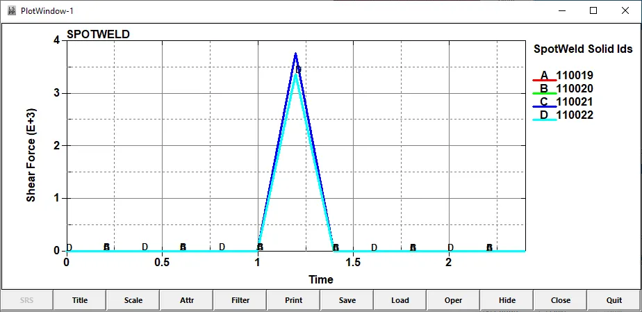
The maximum value of shear force is around 3700N, which is higher than that of beam elements.
RESULTANT FORCE:
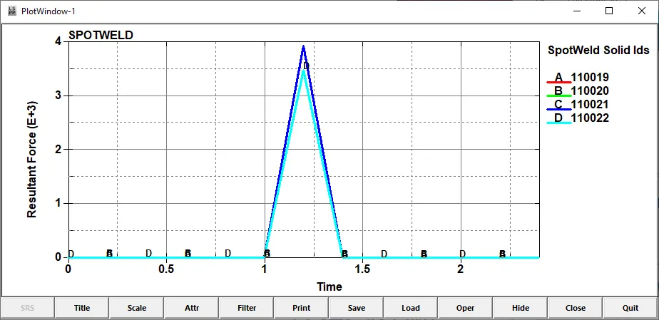
The maximum value of resultant force is around 3900N, which is higher than that of beam elements.
COMPARISON BETWEEN CASE 1 AND CASE 2
- The resultant force and shear force at the time of failure of the solid elements are higher than that of beam elements indicating that the solid elements are more stiffer than the beam elements.
- The run time for case 2 (solid elements) is more than that of case 1.
- The axial force required for the failure of beam elements is higher than that of solid elements.
CONCLUSION:
- The use of beam elements instead of solid elements would speed up the simulation
- Beam elements are computationally more efficient than solid elements.
- Solid elements could resemble better physical properties and can also provide informations about the distribution of stresses, strains etc.,
- Solid elements are more stiffer than beam elements.
- Beam elements are like lines, they do not have physical thickness to collide to each other.
- Beam elements are more stiffer than the solid elements in their axial directions.