Week - 5 - Modelling Spotwelds
Objective:- The aim of this project is to analyse the crash analysis of given part with Beam and Solid Spotweld and to check strength of spotwelds with providing failure of it at half time of simulation and compare the different parameters as follows:
Cross sectional forces at the mid plane.
Acceleration of a node at the midplane.
Maximum directional stress and strain along the longitudinal axis.
Energy plots mentioned and Comparing acceleration and stress/strain plots for the 1.2/1.5 shell thickness box.
All the above scenarios are to be carried out by following the given instructions which include
Creating a *RIGIDWALL_PLANAR.
Considering the steel as the box material.
Assigning an Initial velocity of 50kmph = 13.888 mm/ms.
Following a (g,mm,ms) unit system
Procedure:-
Model:
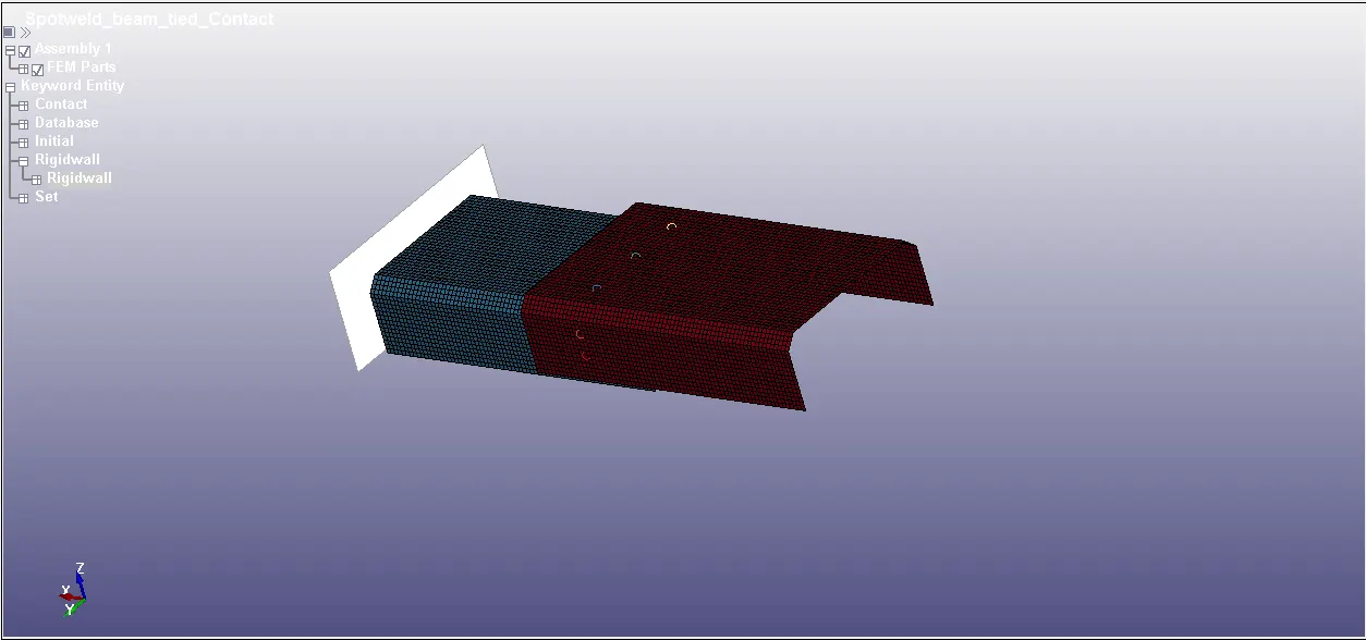
Model with Beam and Solid spotweld :
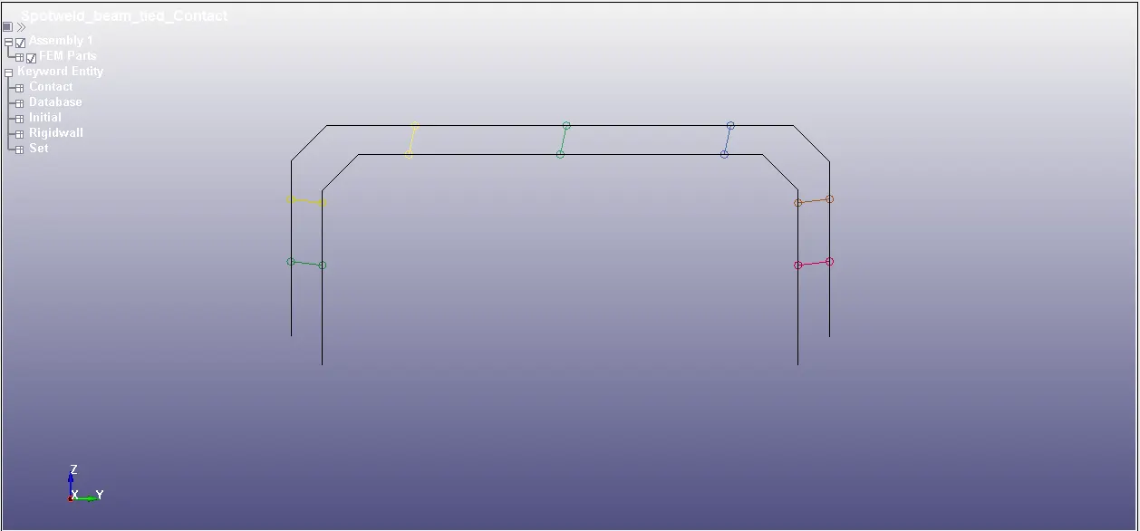
Model with Beam as Spotweld element
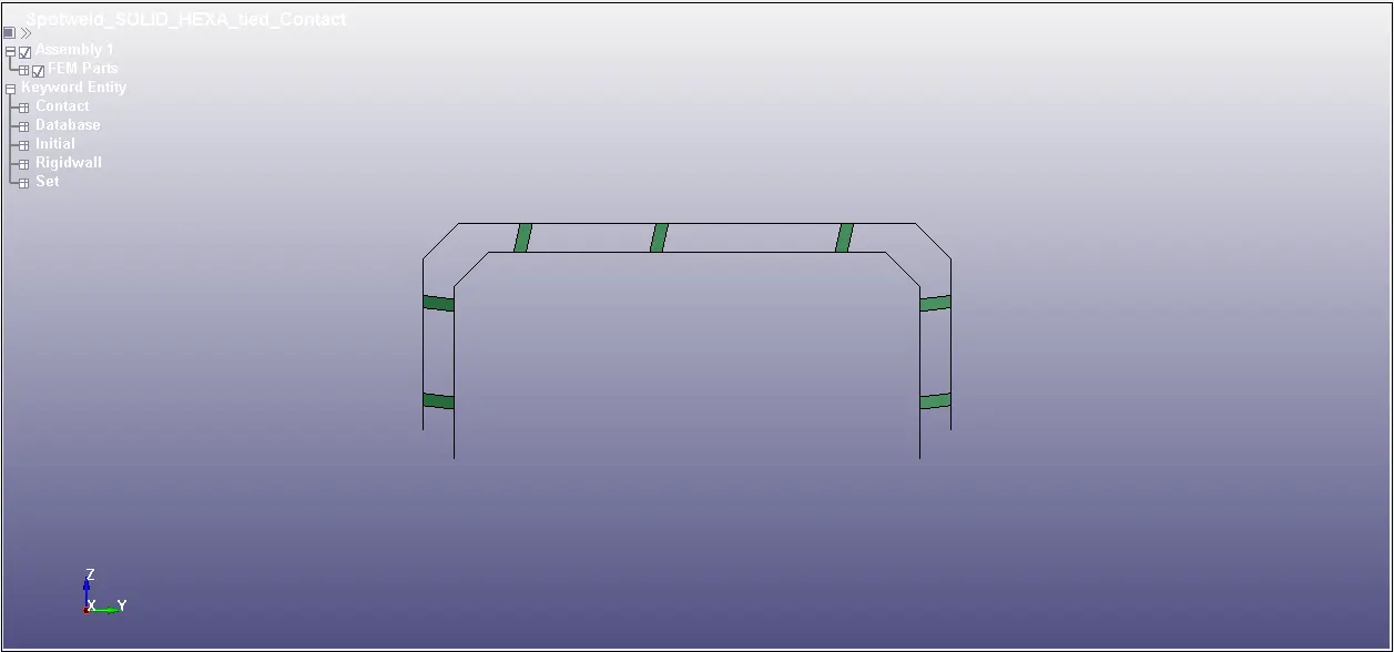
Model with Solid HEXA as spotweld element
Creation of Beam and Solid element:
Beam element is created in LS Prepost by going into Element tools> Element generation> Beam> With beam type as Two noded sets> Pick node 1 and 2 > Apply> Done
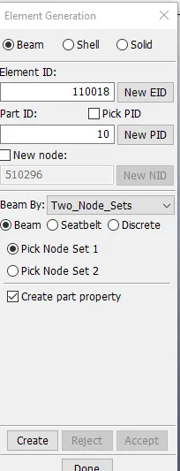
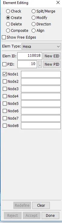
Solid element is created in LS Prepost by going into Element tools> Element edit> Create Solid> Element type HEXA> Pick 8 nodes> Apply> Done.
Section for Top and Bottom part:
Shell elements are given thickness of 1.5 mm with Element formulation ELFORM 16 fully integrated shell element.
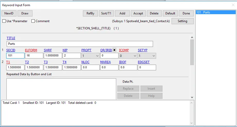
Top and Bottom part with Section as SHELL
Section for Beam Spotweld:
As we are using MAT_100 Spotweld material so we have given Element formulation for Beam as ELFORM 9 with OR=4 . This is recommended value when MAT_100 Spotweld material card is in use.
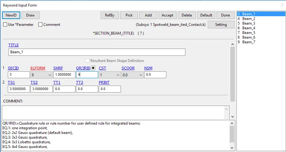
Section Beam card
Section for SOLID Spotweld:
As we are using MAT_100 Spotweld material so we have given Element formulation for SOLID as ELFORM 1 with OR=4 . This is recommended value when MAT_100 Spotweld material card is in use.
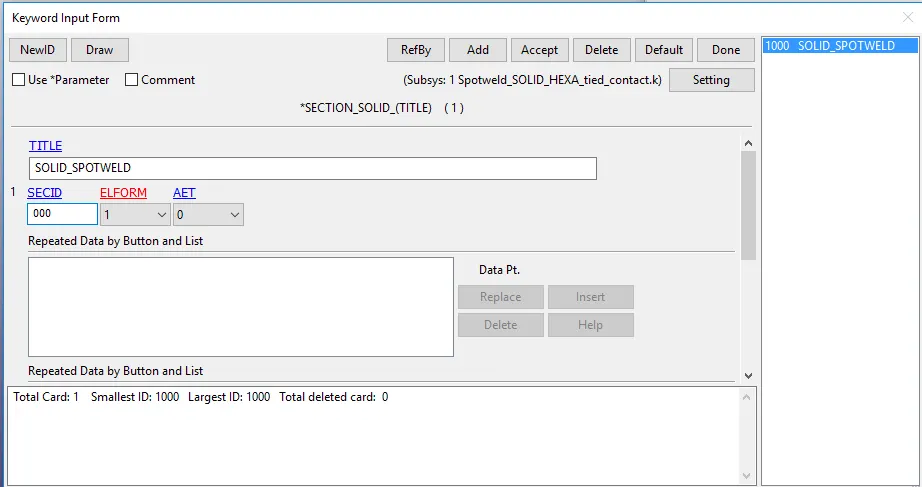
Section SOLID card
Materials:
For Top and Bottom shell parts MAT_001_Elastic with properties of Steel is used while for Spotweld , MAT_100_SPOTWELD is used. In MAT_100_SPOTWELD card we will define the types by which we want our spotweld to fail. In this simulation , we have given Time base failure TFAIL=5 ms which is half of our complete simulation time.
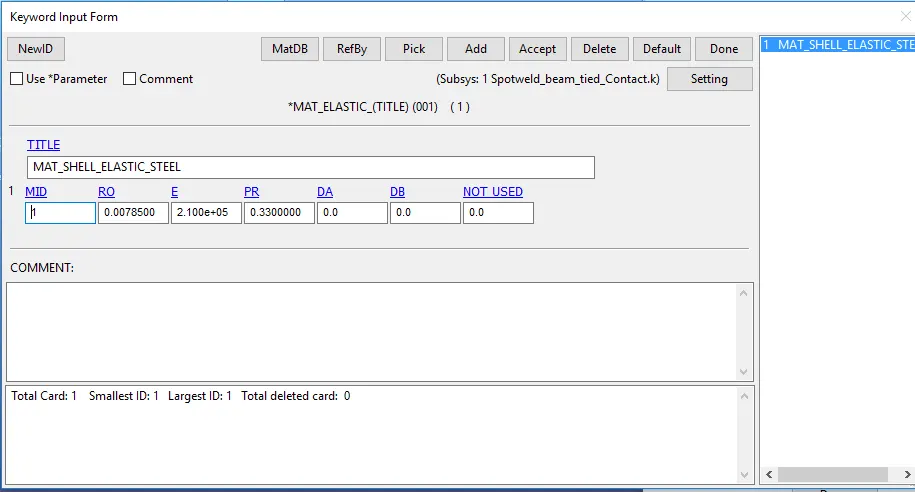
Material for Top and Bottom part
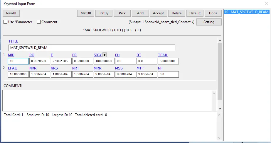
Material for Spotweld Elements
Parts:
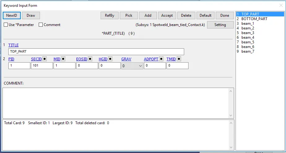
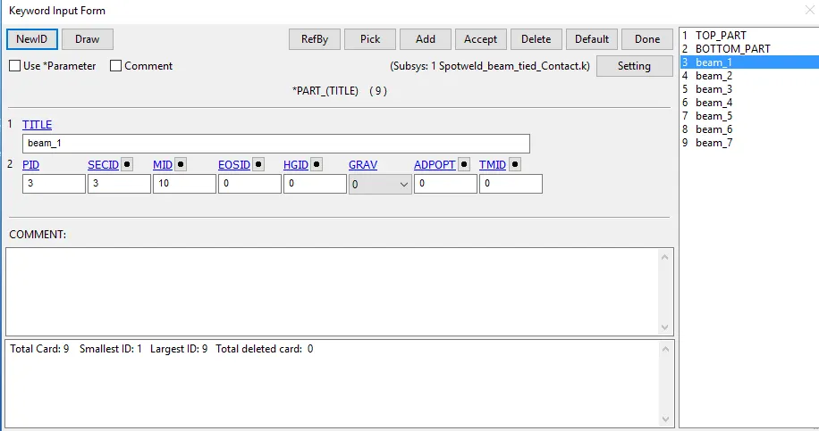
In parts , We assigned the Section and Material with its ID.
Initial Velocity:
Since it is crash simulation , all nodes of parts are selected and given velocity of 13.88 mm/ms
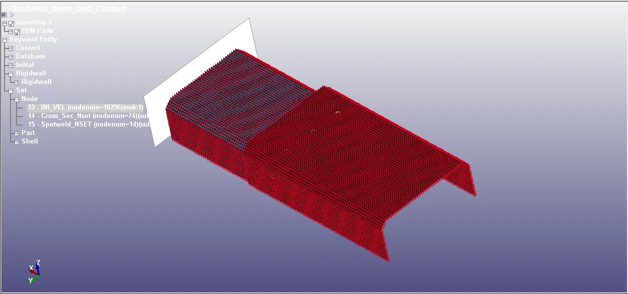
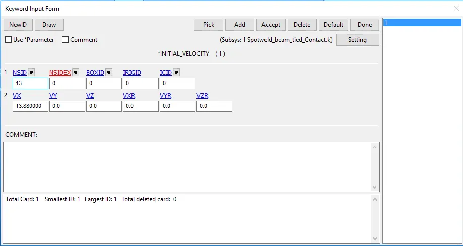
Initial velocity card
Contacts:
An AUTOMATIC_SINGLE_SURFACE contact has been defined so that the shell parts do not penetrate each other when the beam elements fail and a TIED_SHELL_EDGE_TO_SURFACE contact also has been created for the contact between edges of the beam elements and shell surfaces. In the AUTOMATIC_SINGLE_SURFACE contact both the shell parts acts as master and slave so only one slave id has been imputed. In the TIED_SHELL_EDGE_TO_SURFACE contact a Node set ID(beam elements) was applied as slave type and parts(shell parts) are masters.
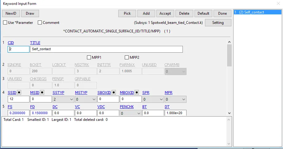
Self contact card
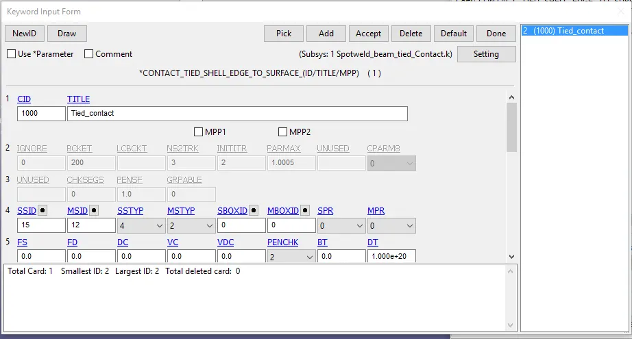
Tied_shell_edge_to_Surface contact card
Control cards:
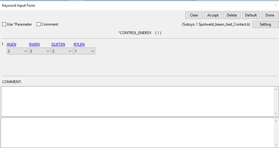
Control Energy
Control_Energy card is used for controlling hourglass energy and sliding energy
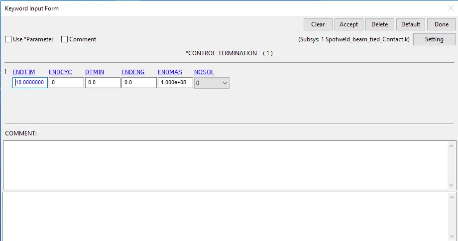
Control Termination
Control_termination is used for giving end time of simulation which in our case is 10 ms
Outputs:
Proof of Spotwelds faling at 5 ms
By opening message file in Notepad++ , we can claerly see that all spotwelds are failing at 5 ms which was given as TFAIL in our Spotweld material card.
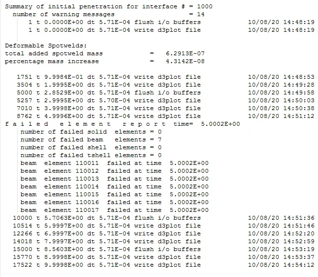
Failure of Beam element Spotweld
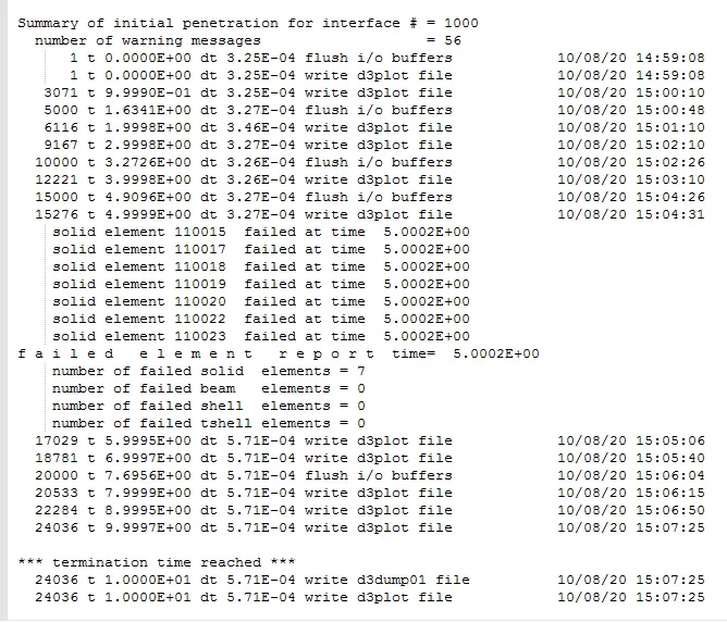
Failure of Solid element Spotweld
Animation of Simulation:
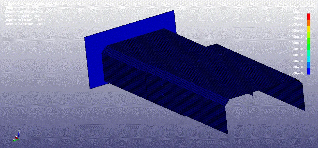
For beam spotweld
For Solid Spotweld
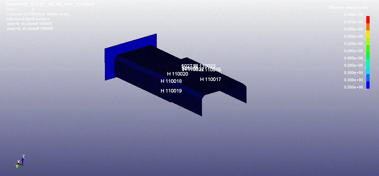
From the simulation , it can be seen that all the spotwelds are failing around 5 ms which was given as spotweld failure time.
Acceleration along X direction of two nodes at mid plane:
The values of accelerations are obtained for two nodes at middle during point of impact with rigid wall , failure of beam spotweld and at end of simulation.
For Beam spotweld,
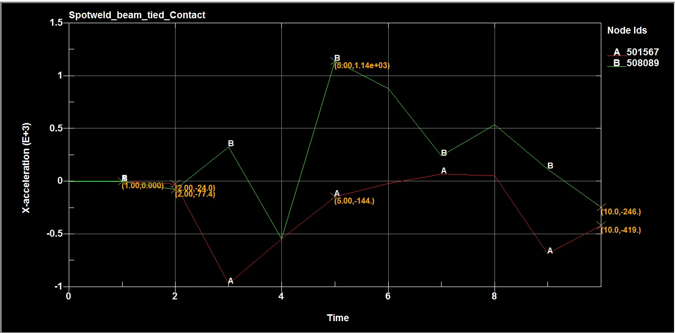
The value of acceleration along X direction for NODE 508089 and 501567 at instant of impact (2 ms) are -24 mm/ms2 and -77.4 mm/ms2 , at failure of spotwelds (5 ms) are 1.14e+03 mm/ms2 and -144 mm/ms2 , at end of simulation (10 ms) are -246 mm/ms2 and -419 mm/ms2 respectively.
For Solid spotweld,
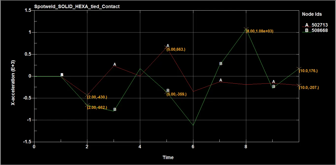
The value of acceleration along X direction for NODE 502713 and 508668 at instant of impact (2 ms) are -430 mm/ms2 and -662 mm/ms2 , at failure of spotwelds (5 ms) are 663 mm/ms2 and -359 mm/ms2 , at end of simulation (10 ms) are -207 mm/ms2 and 176 mm/ms2 respectively.
Resultant Acceleration of two nodes at mid plane:
The values of accelerations are obtained for two nodes at middle during point of impact with rigid wall , failure of beam spotweld and at end of simulation.
For Beam spotweld,
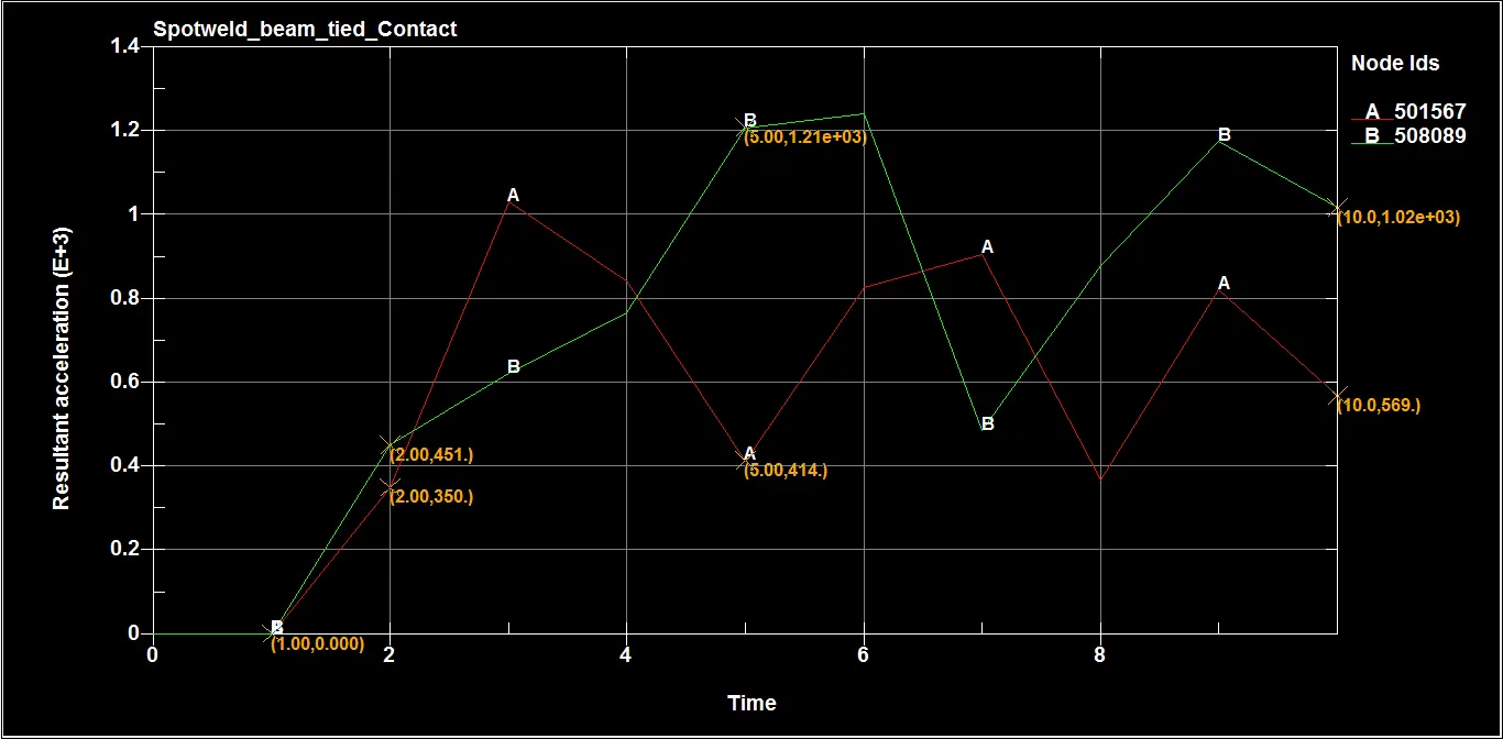
The value of resultant acceleration for NODE 508089 and 501567 at instant of impact (2 ms) are 350 mm/ms2 and 451 mm/ms2 , at failure of spotwelds (5 ms) are 414 mm/ms2 and 1.21e+03 mm/ms2 , at end of simulation (10 ms) are 569 mm/ms2 and 1.02e+03 mm/ms2 respectively.
For Solid spotweld,
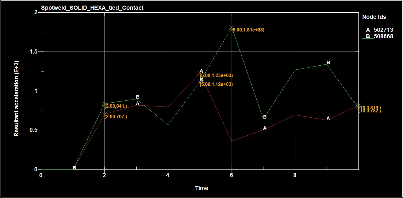
The value of resultant acceleration for NODE 502713 and 508668 at instant of impact (2 ms) are 707 mm/ms2 and 841 mm/ms2 , at failure of spotwelds (5 ms) are 1.23e+03 mm/ms2 and 1.12e+03 mm/ms2 , at end of simulation (10 ms) are 819 mm/ms2 and 782 mm/ms2 respectively.
Cross sectional force at mid plane:
For Beam spotweld,
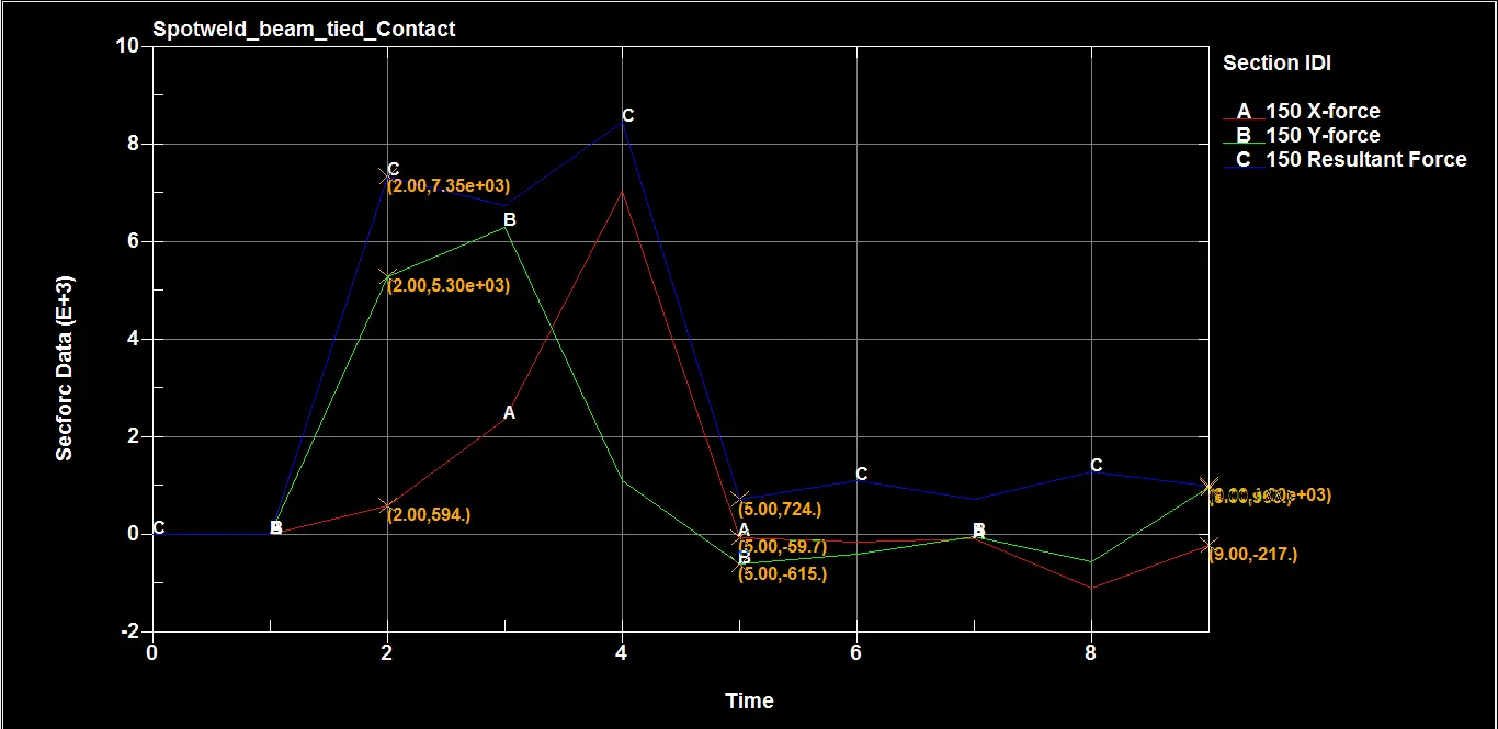
Table with data:
| Parameters | At instant of impact 2 ms | At failure of spotwelds 5 ms | At end of simulation 10 ms |
| Cross-sectional force along X (N) | 594 | -615 | 966 |
| Cross-sectional force along Y (N) | 5.30e+03 | -59.7 | -217 |
| Resultant cross sectional force (N) | 7.35e+03 | 724 | 1e+03 |
For Solid spotweld,
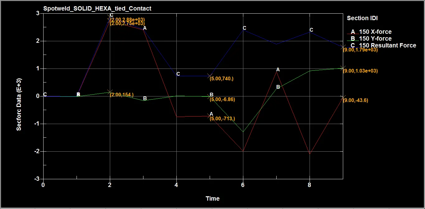
| Parameters | At instant of impact 2 ms | At failure of spotwelds 5 ms | At end of simulation 10 ms |
| Cross-sectional force along X (N) | 2.75e+03 | -713 | -43.6 |
| Cross-sectional force along Y (N) | 154 | -6.86 | 1.03e+03 |
| Resultant cross sectional force (N) | 2.88e+03 | 740 | 1.79e+03 |
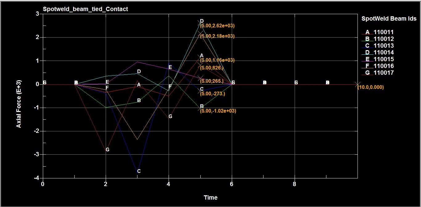
Axial Force obtained by Spotwelds:-
For beam spotweld
For Solid spotweld
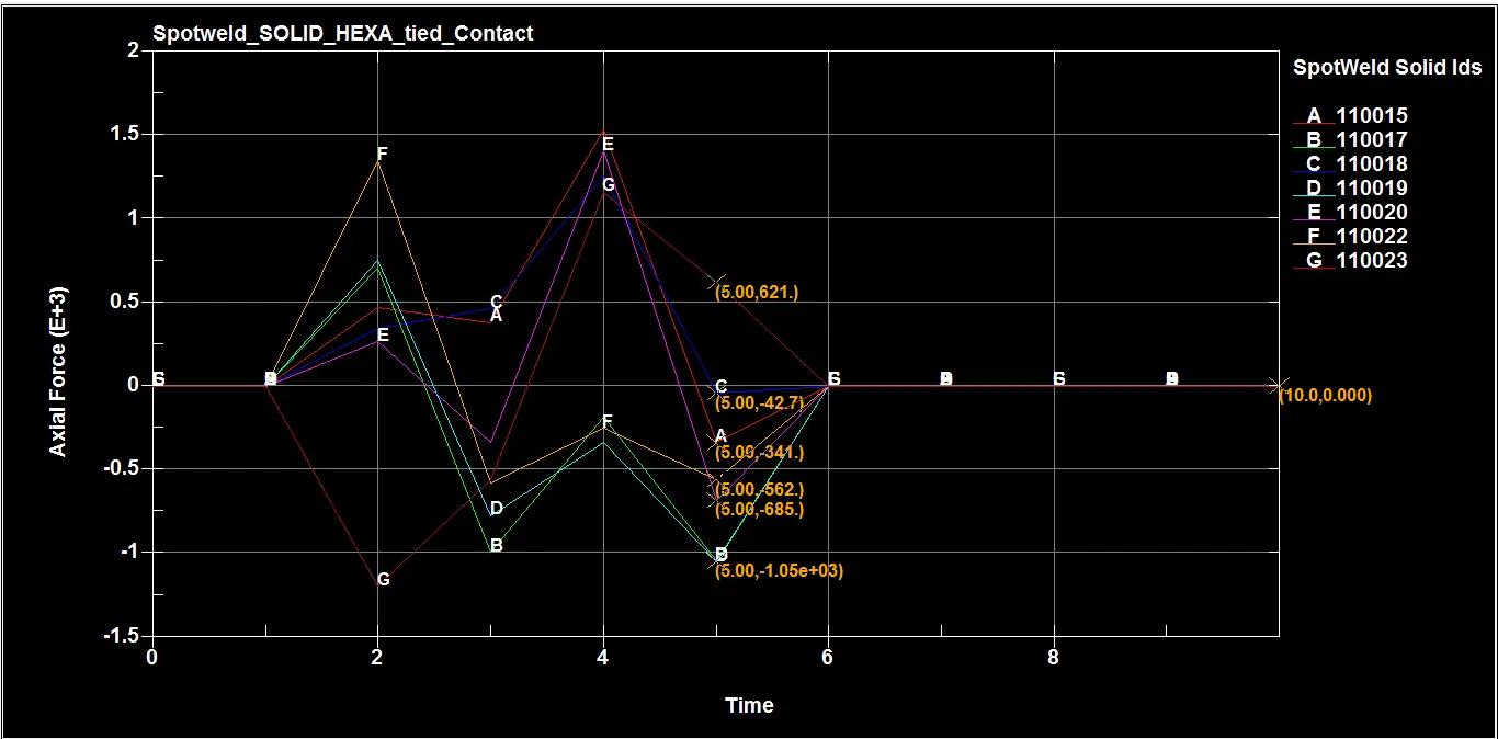
Maximum Axial force obtained by Beam and Solid spotwelds is 2.62e+03 N and 621 N neglecting the negative directional values . From the plot , we can see that spotweld has failed after 5 ms and at the end of simulation the value of it is 0 which clearly indicates that all the spotwelds have failed.
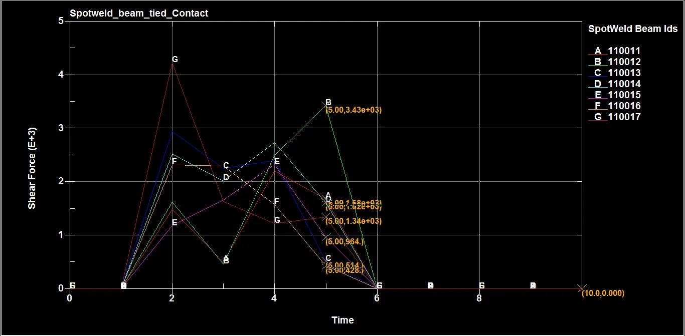
Axial Force obtained by Spotwelds:-
For beam spotweld
For Solid spotweld
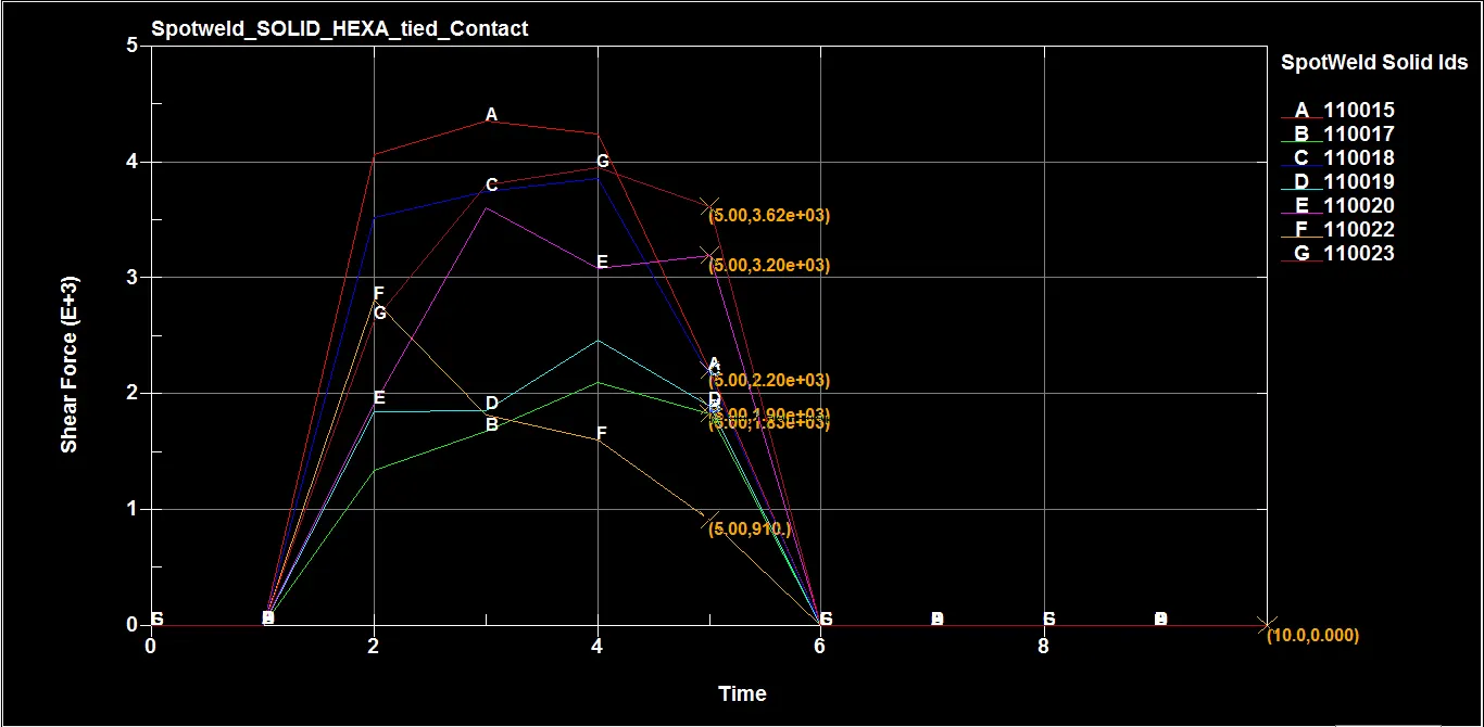
Maximum Shear force obtained by Beam and Solid spotwelds is 3.43e+03 N and 3.62e+03 N respectively at time of failure of spotwelds.
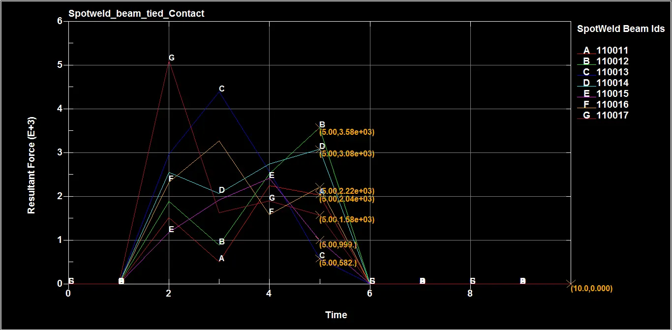
Resultant Force obtained by Spotwelds:-
For beam spotweld
For Solid spotweld
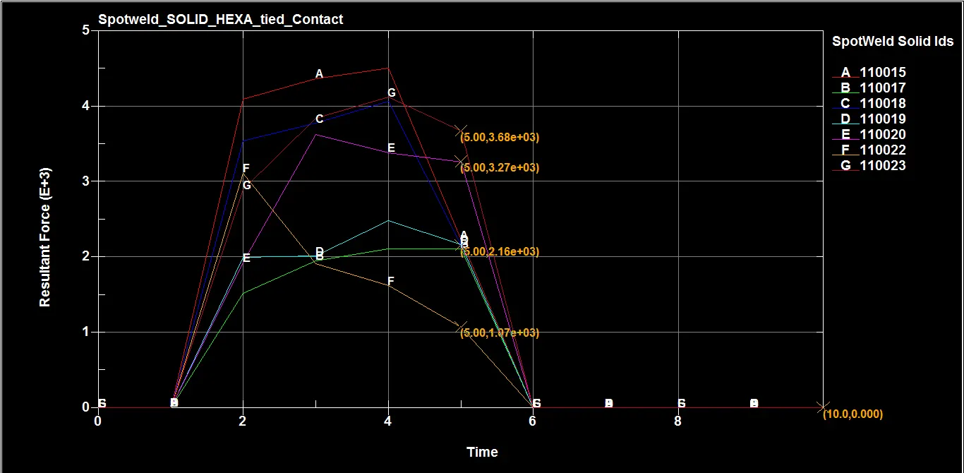
Maximum Resultant force obtained by Beam and Solid spotwelds is 3.58e+03 N and 3.68e+03 N respectively at time of failure of spotwelds.
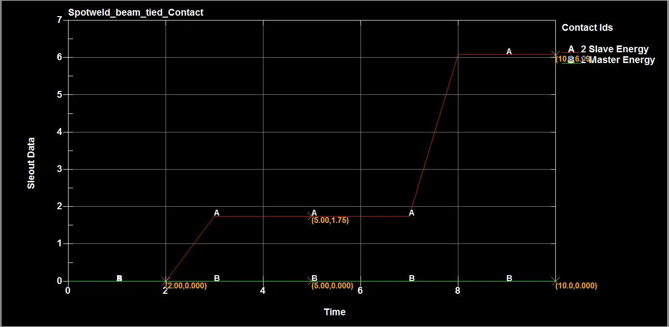
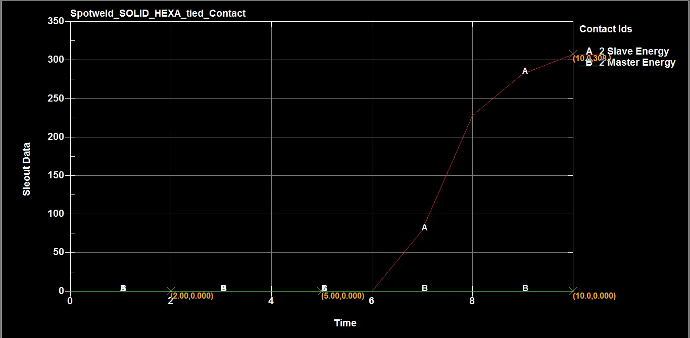
SLEOUT data :
SLEOUT card is generally use for obtaining data related with Sliding energy present in Contacts.
SLEOUT data for Automatic single surface to surface contact
For Beam spotweld,
For Solid spotweld,
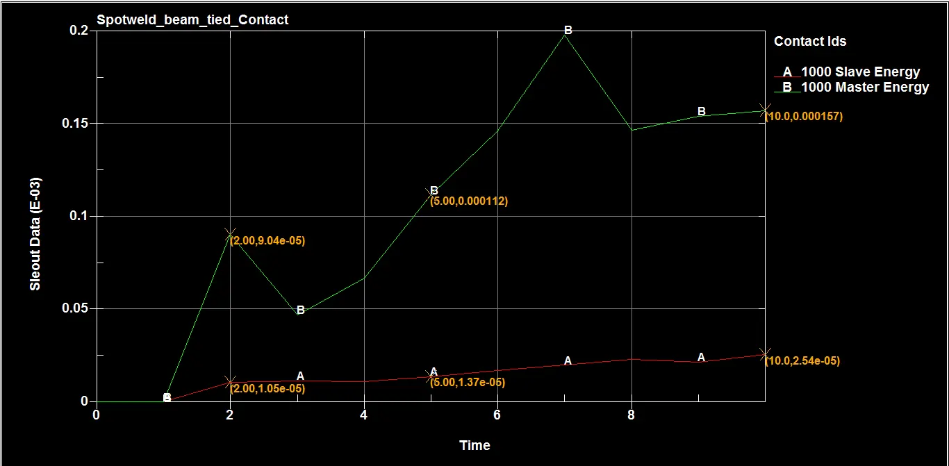
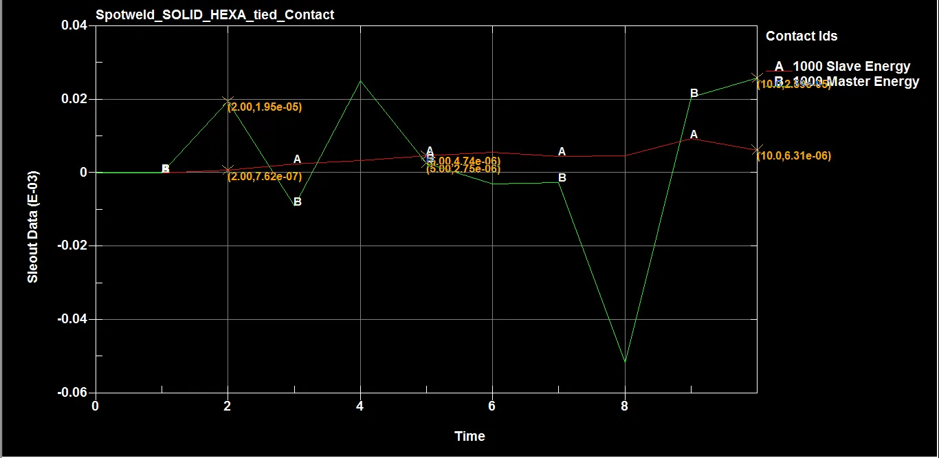
SLEOUT data for Tied shell edge to surface contact
For Beam spotweld,
For Solid spotweld,
Contact force:-
For automatic single surface , contact force of both slave and master are zero. But for Tied shell edge to surface contact , it consists of Slave and Master contact forces. Slave part is taken by all the spotwelds while master part is taken by Top and Bottom part as an set.
Slave Contact force
For Beam spotweld,
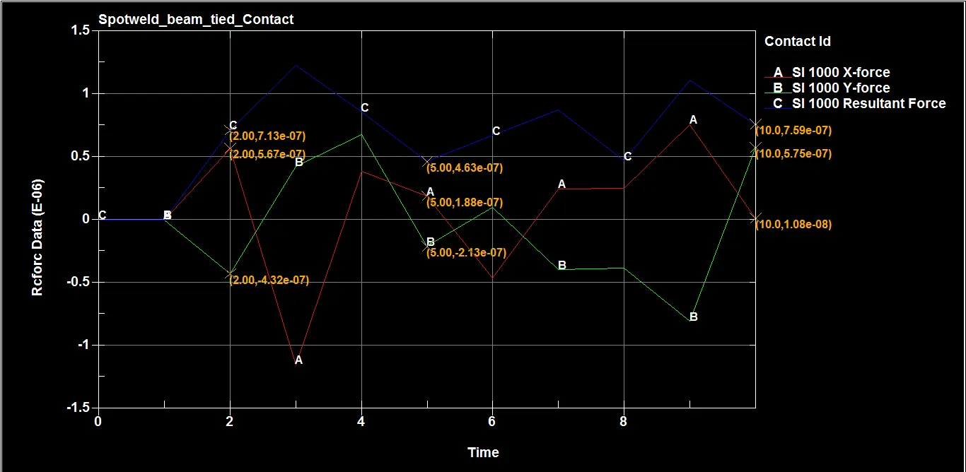
Table with data:
| Parameters | At instant of impact 2 ms | At failure of spotwelds 5 ms | At end of simulation 10 ms |
| Contact force along X (N) | 5.67e-07 | 1.88e-07 | 1.08e-08 |
| Contact force along Y (N) | -4.32e-07 | - 2.13e-07 | 5.75e-07 |
| Resultant contact force (N) | 7.13e-07 | 4.63e-07 | 7.59e-07 |
For Solid spotweld,
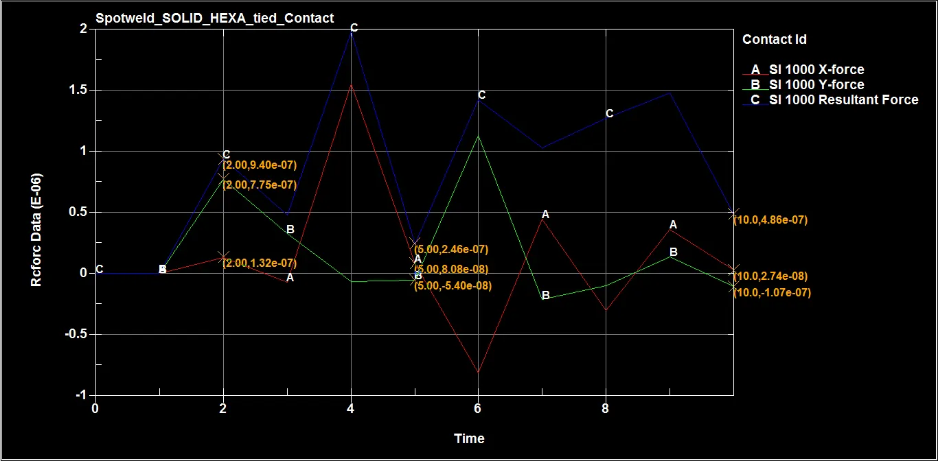
Table with data:
| Parameters | At instant of impact 2 ms | At failure of spotwelds 5 ms | At end of simulation 10 ms |
| Contact force along X (N) | 1.32e-07 | 8.08e-08 | 2.74e-08 |
| Contact force along Y (N) | 7.75e-07 | - 5.40e-08 | - 1.07e-07 |
| Resultant contact force (N) | 9.40e-07 | 2.46e-07 | 4.86e-07 |
Master Contact force
For Beam spotweld,
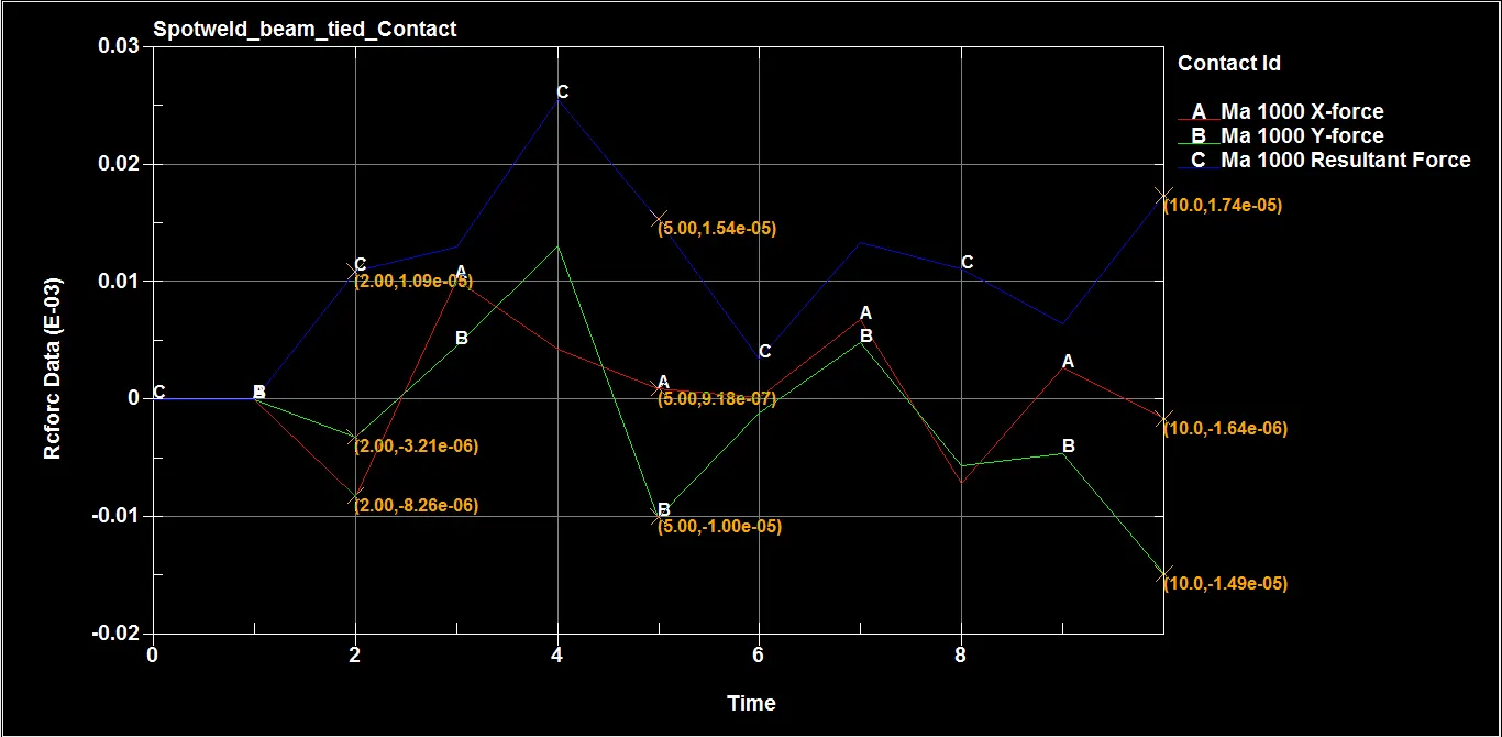
Table with data:
| Parameters | At instant of impact 2 ms | At failure of spotwelds 5 ms | At end of simulation 10 ms |
| Contact force along X (N) | -8.26e-06 | 9.18e-07 | -1.64e-06 |
| Contact force along Y (N) | -3.21e-06 | - 1.00e-05 | -1.49e-05 |
| Resultant contact force (N) | 1.09e-05 | 1.54e-05 | 1.74e-05 |
For Solid spotweld,
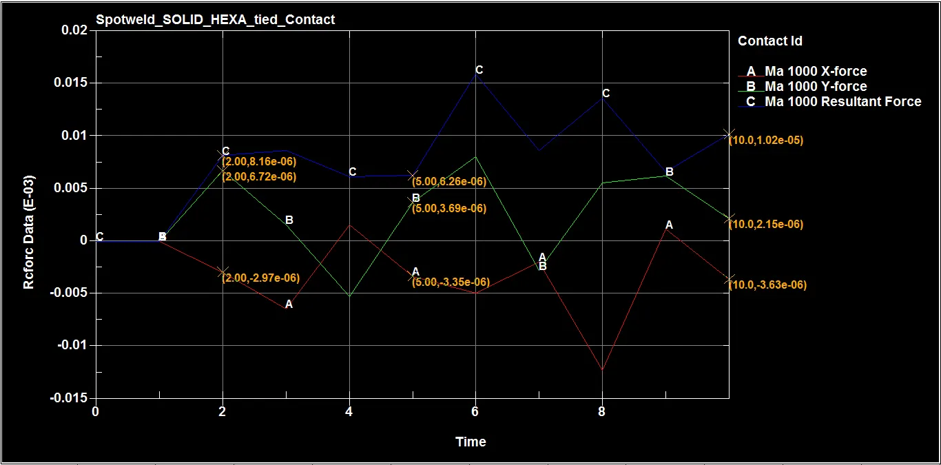
Table with data:
| Parameters | At instant of impact 2 ms | At failure of spotwelds 5 ms | At end of simulation 10 ms |
| Contact force along X (N) | -2.97e-06 | -3.35e-06 | -3.63e-06 |
| Contact force along Y (N) | 8.16e-06 | 3.69e-06 | 2.15e-06 |
| Resultant contact force (N) | 6.72e-06 | 6.26e-06 | 1.02e-05 |
Directional stress:
Stress along X direction
During impact at 2 ms,
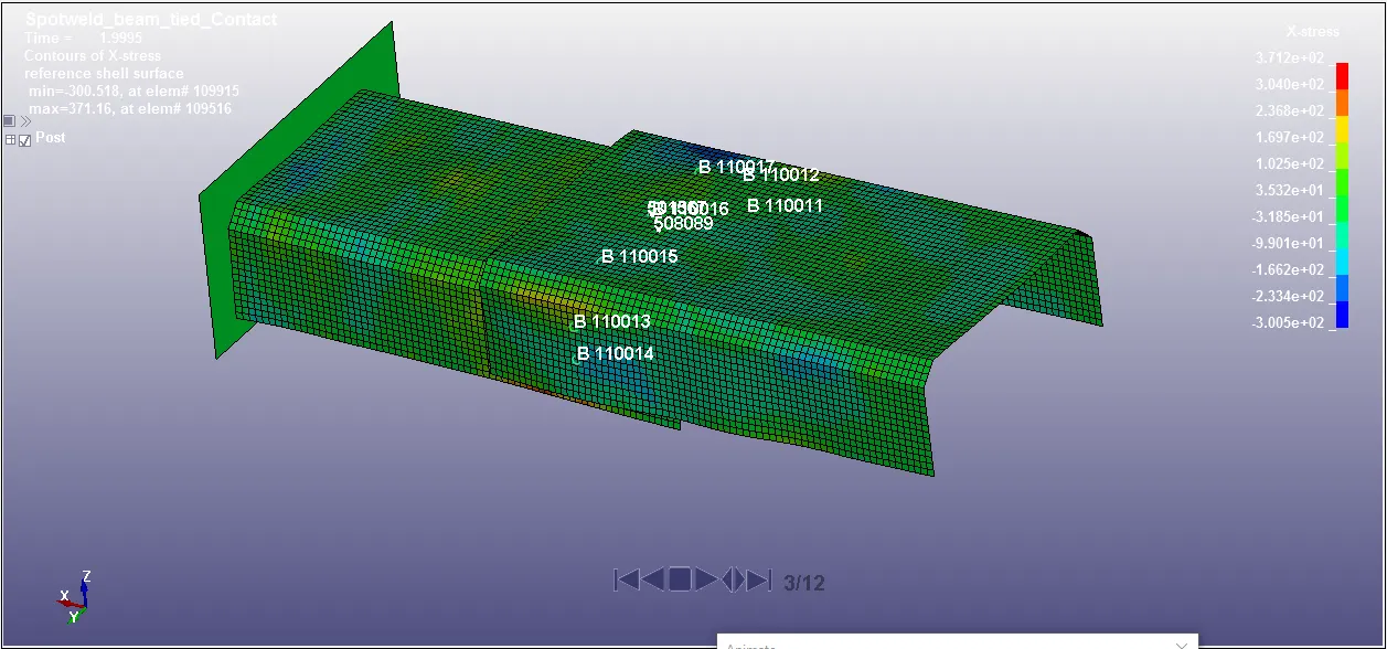
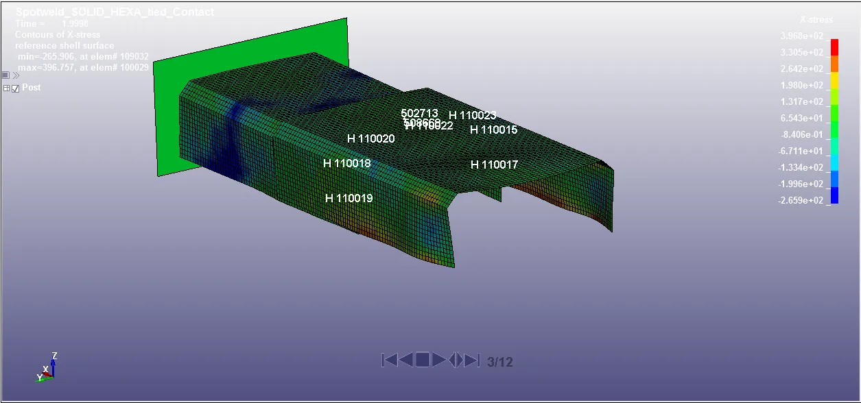
Maximum X- directional stress obtained by beam and solid spotweld at instant of impact 2 ms is 371.2 MPa and 396.8 MPa.
Just before failure of spotweld at 4.99 ms,
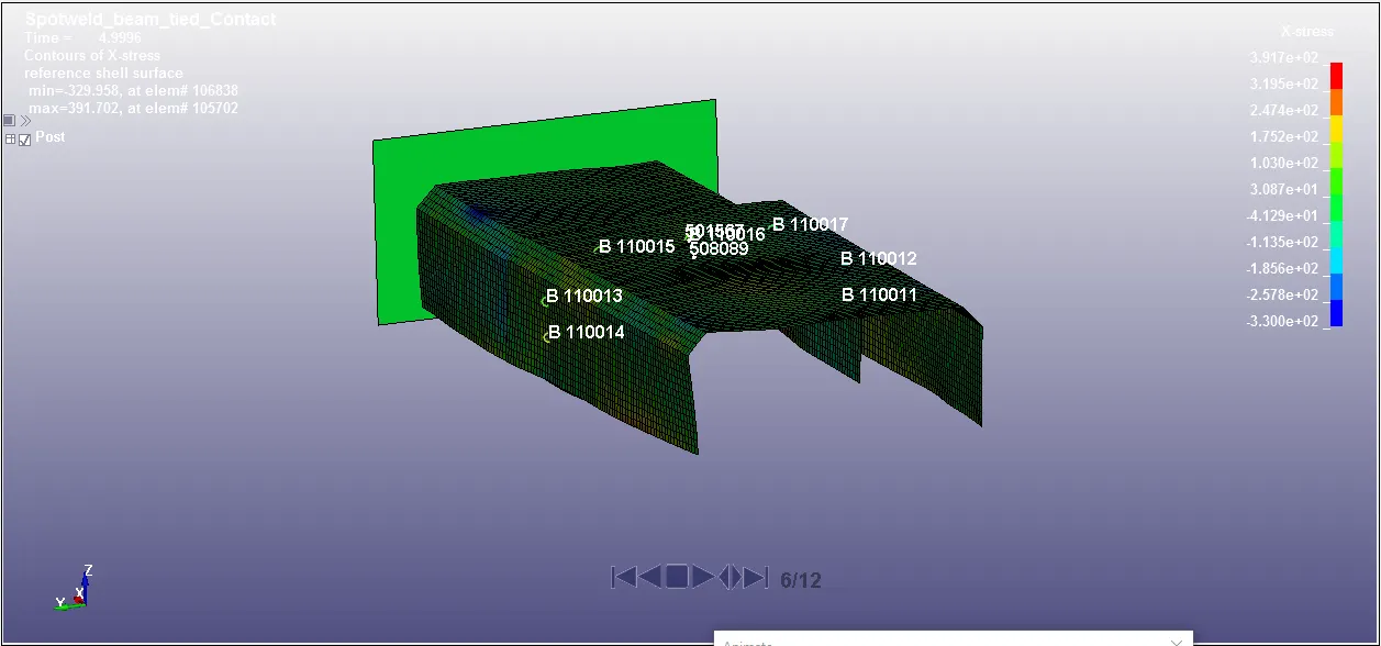
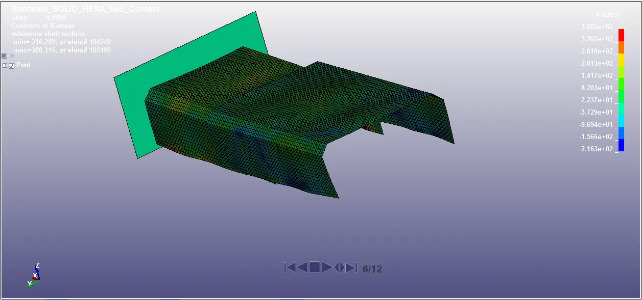
Maximum X- directional stress obtained by beam and solid spotweld at just before spotweld failure 4.99 ms is 391.7 MPa and 380.3 MPa.
Just after failure of spotweld at 5.99 ms,
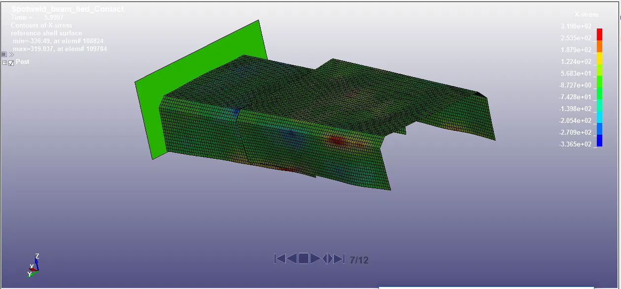
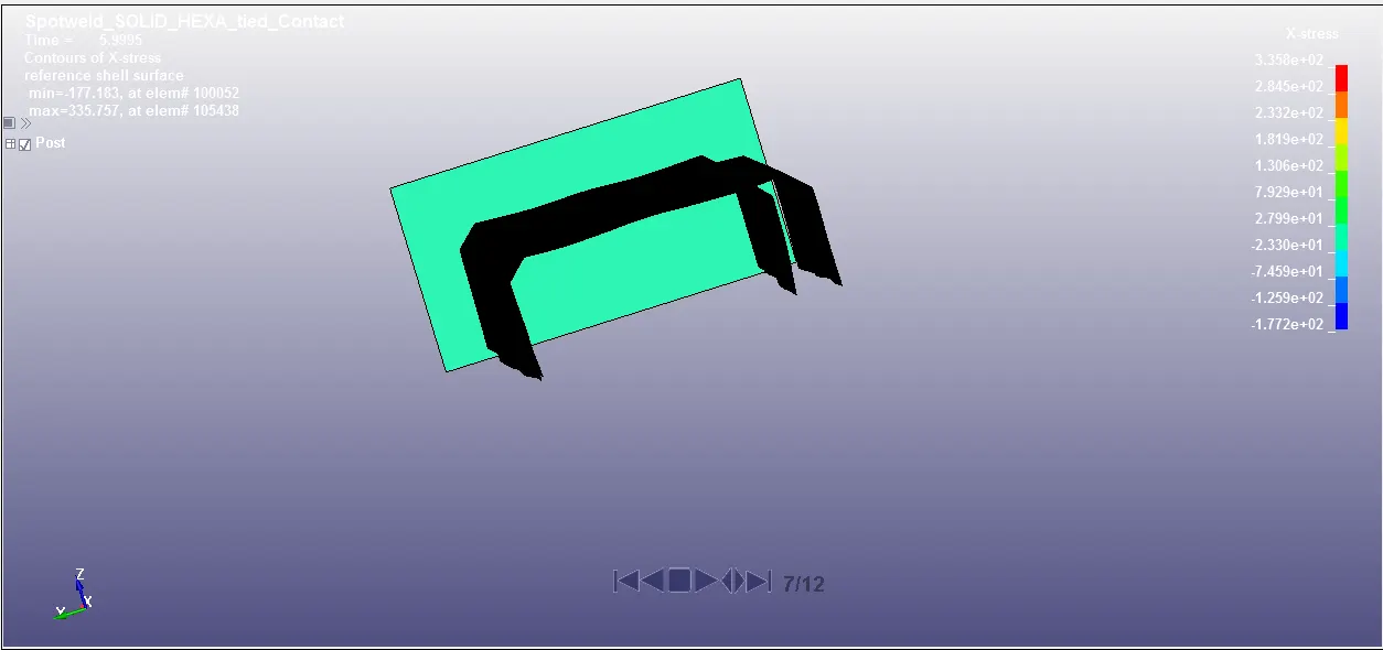
Maximum X- directional stress obtained by beam and solid spotweld at just after spotweld failure 5.99 ms is 319.0 MPa and 335.8 MPa.
At the end of simulation at 10 ms,
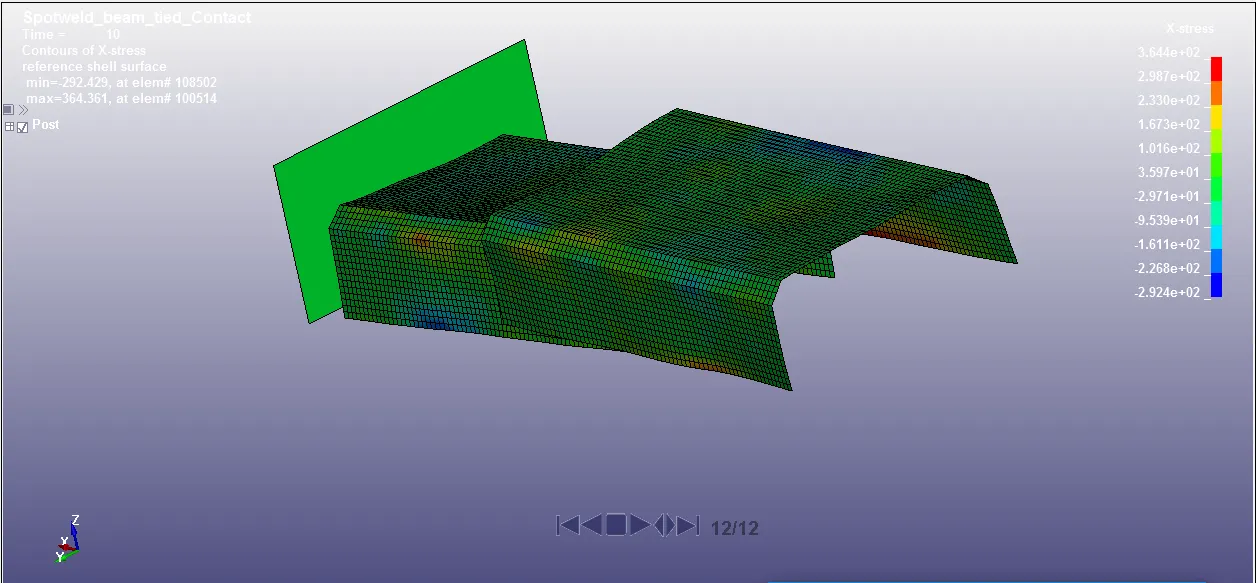
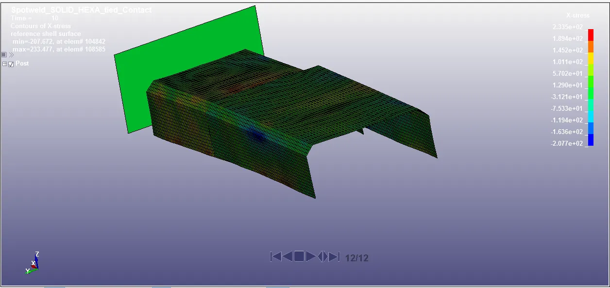
Maximum X- directional stress obtained by beam and solid spotweld at end of simulation 10 ms is 364.4 MPa and 233.5 MPa.
Stress along Y direction
During impact at 2 ms,
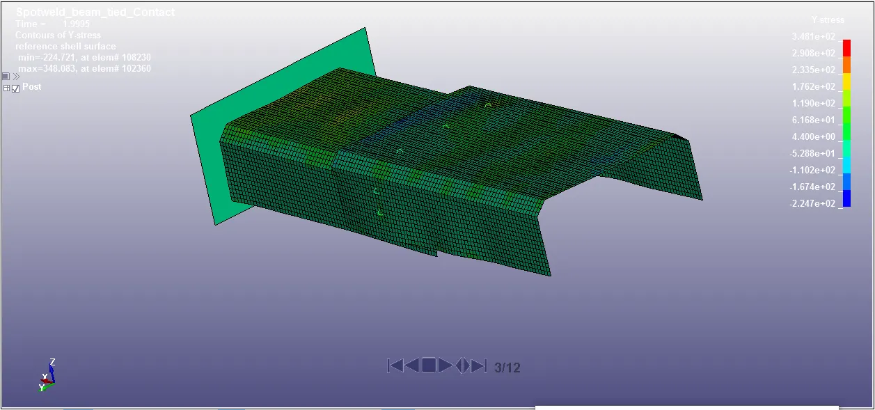
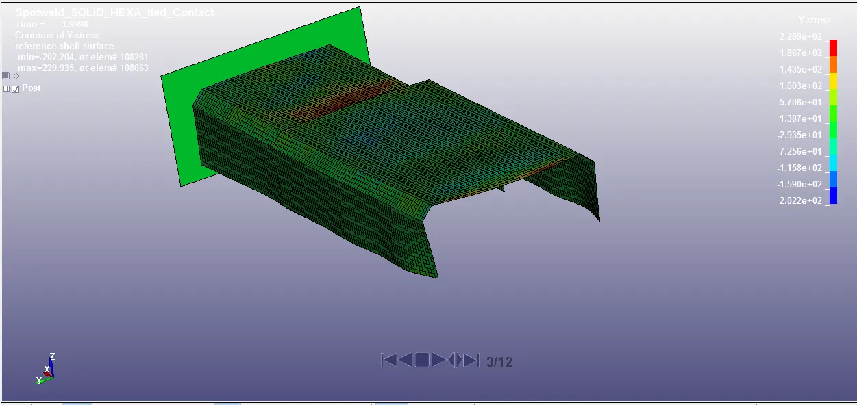
Maximum Y- directional stress obtained by beam and solid spotweld at instant of impact 2 ms is 348.1 MPa and 229.9 MPa.
Just before failure of spotweld at 4.99 ms,
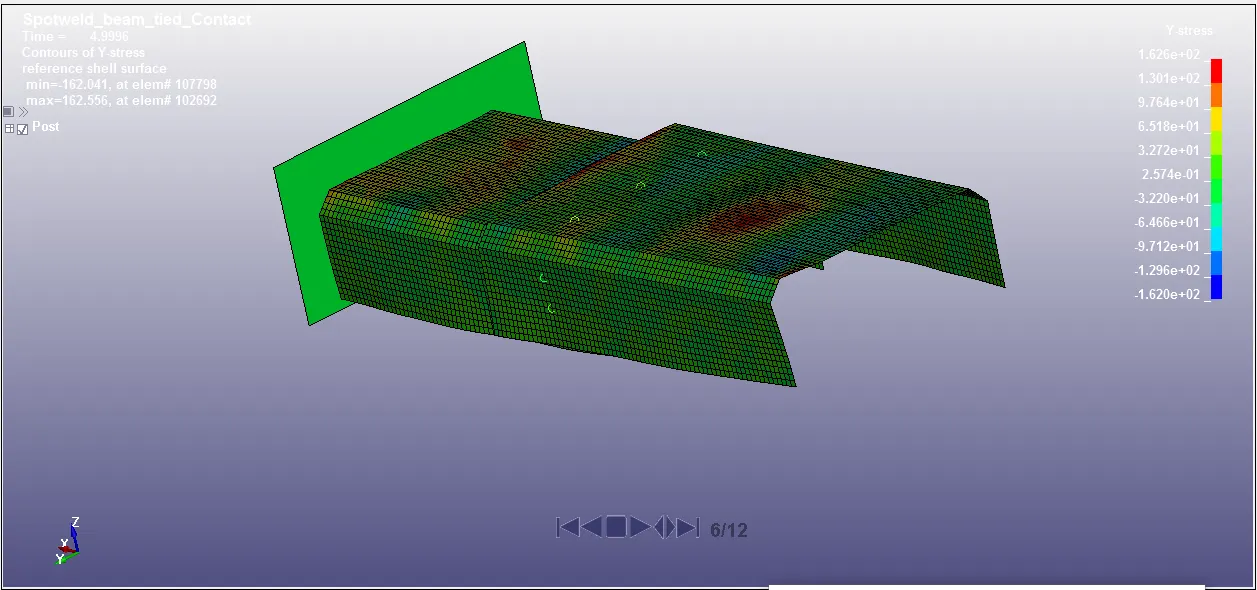
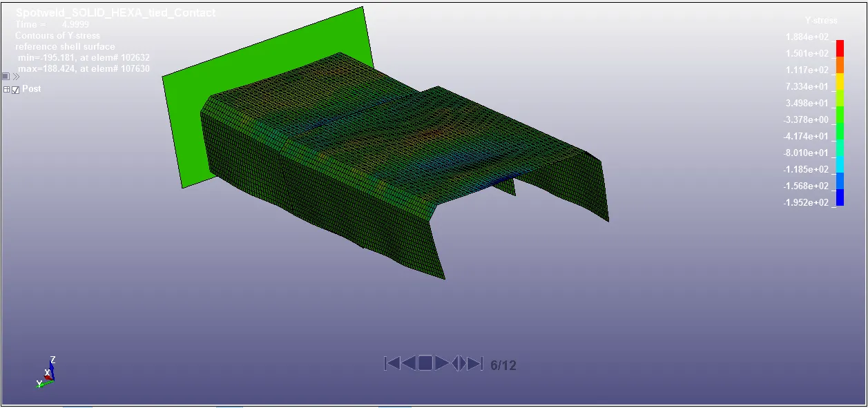
Maximum Y- directional stress obtained by beam and solid spotweld at just before spotweld failure 4.99 ms is 162.6 MPa and 188.4 MPa.
Just after failure of spotweld at 5.99 ms,
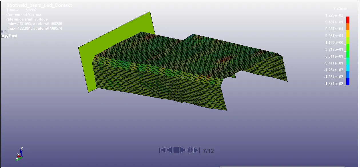
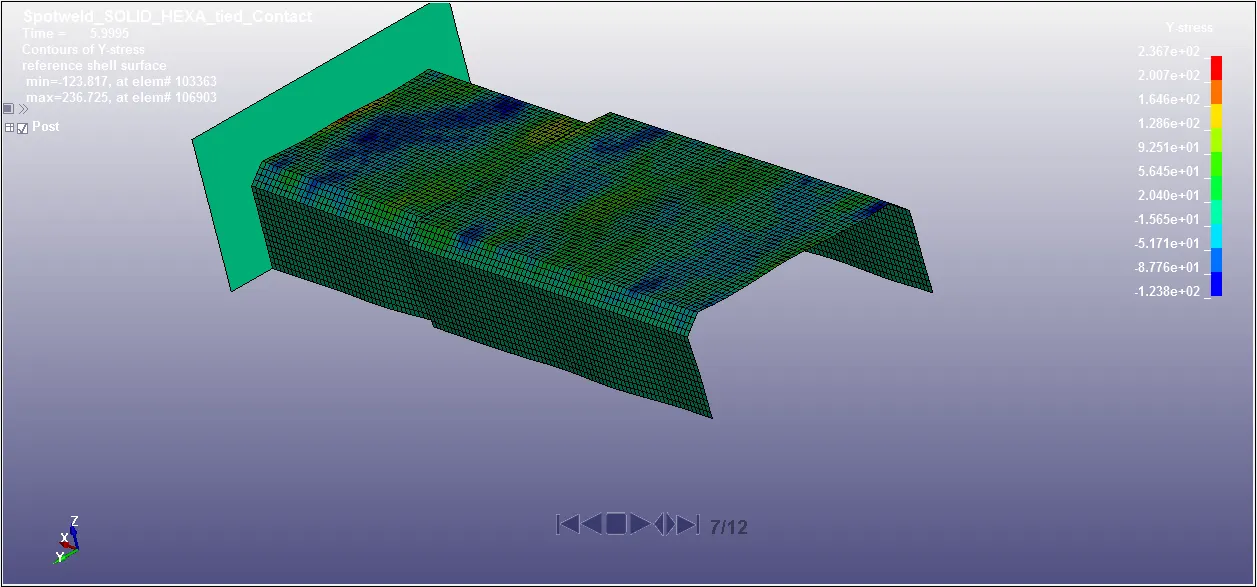
Maximum Y- directional stress obtained by beam and solid spotweld at just after spotweld failure 5.99 ms is 122.9 MPa and 236.7 MPa.
At the end of simulation at 10 ms,
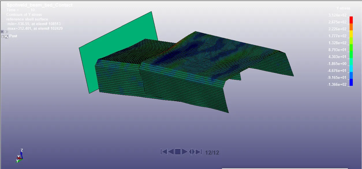
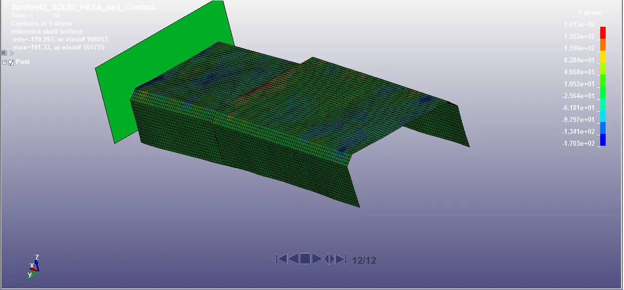
Maximum Y- directional stress obtained by beam and solid spotweld at end of simulation 10 ms is 312.4 MPa and 191.3 MPa.
Strain along X direction
During impact at 2 ms,
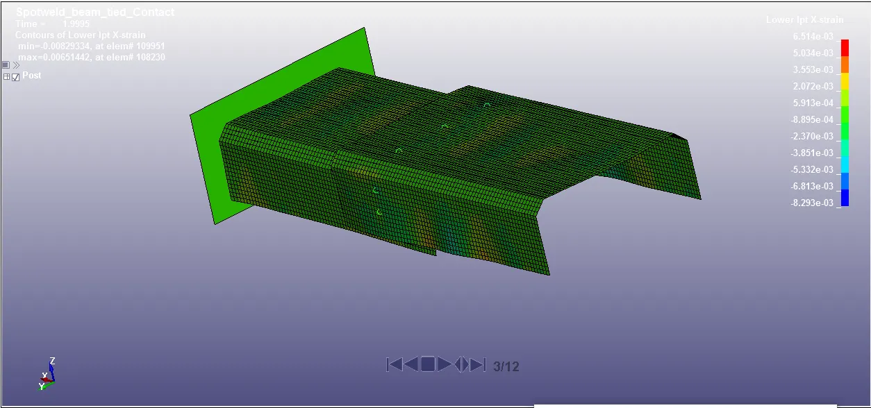
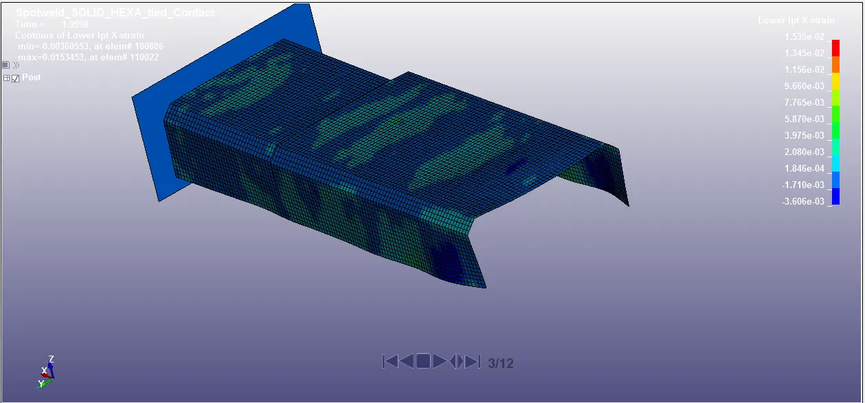
Maximum X- directional strain obtained by beam and solid spotweld at instant of impact 2 ms is 0.00651 and 0.001535 .
Just before failure of spotweld at 4.99 ms,
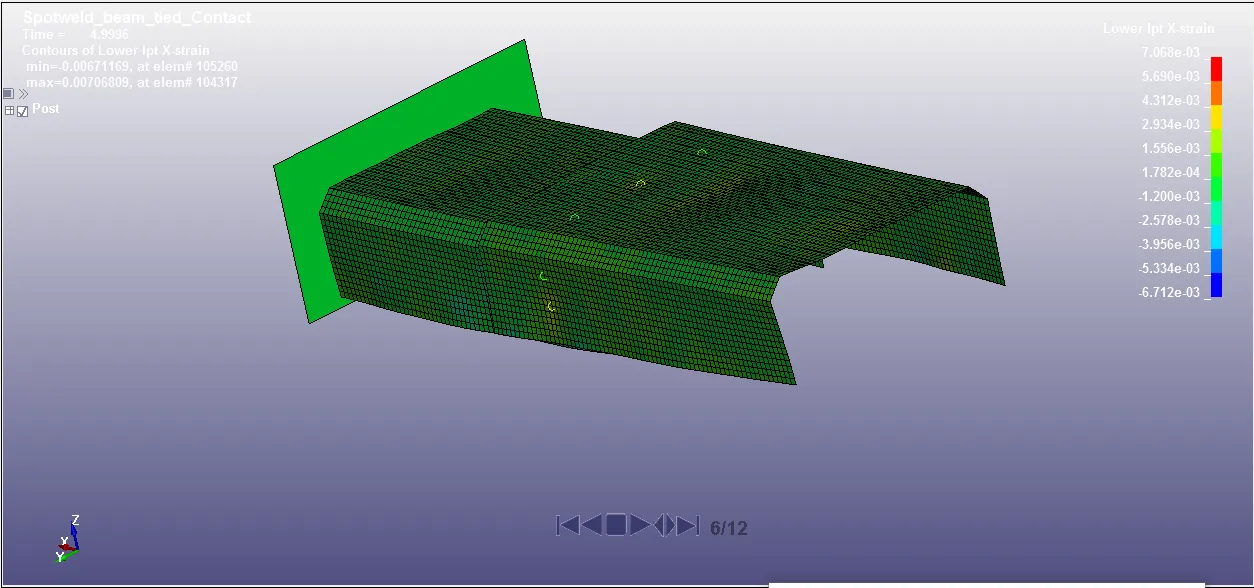
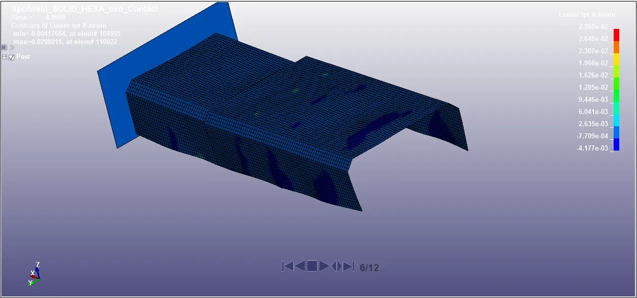
Maximum X- directional strain obtained by beam and solid spotweld at just before spotweld failure 4.99 ms is 0.007068 and 0.02988 .
Just after failure of spotweld at 5.99 ms,
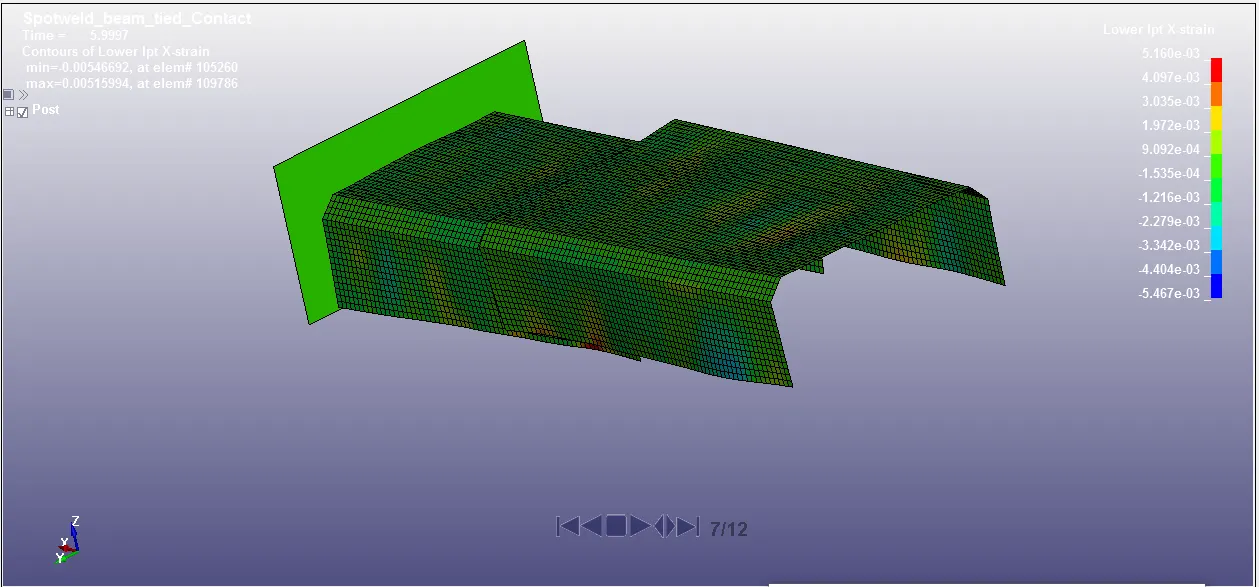
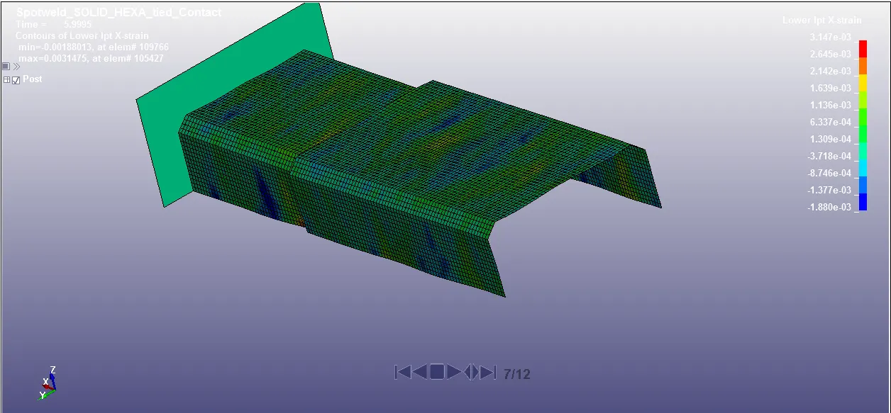
Maximum X- directional strain obtained by beam and solid spotweld at just after spotweld failure 5.99 ms is 0.00516 and 0.00314 .
At the end of simulation at 10 ms,
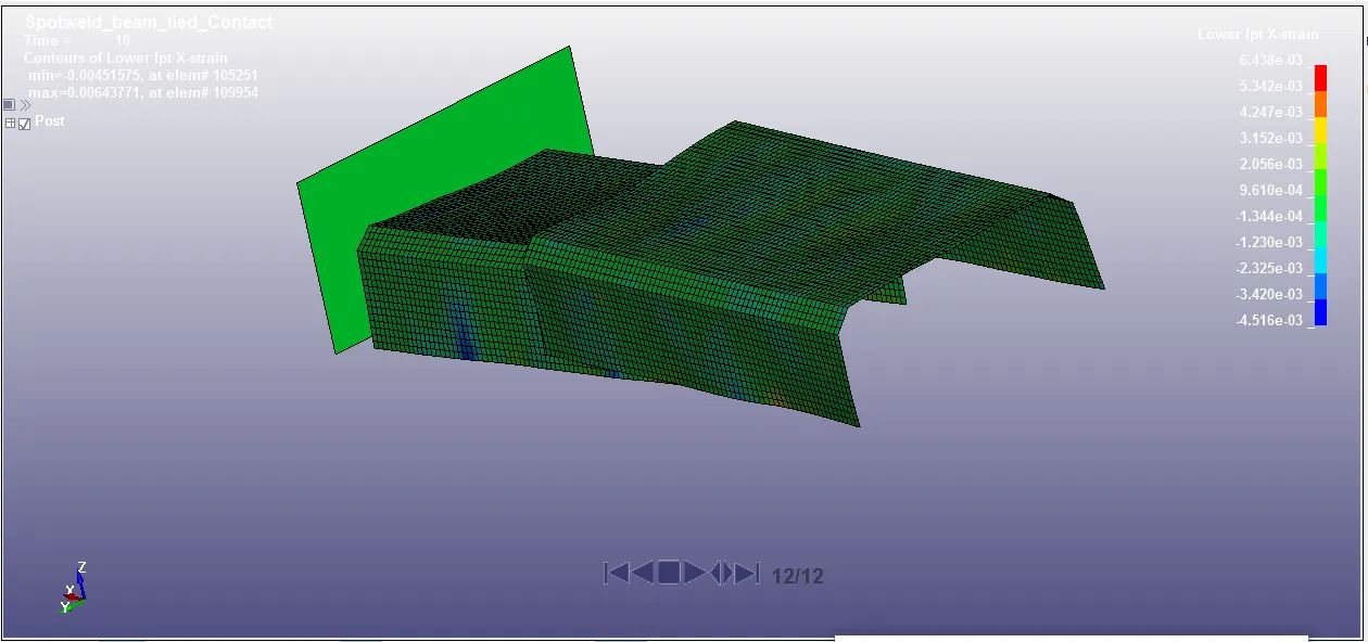
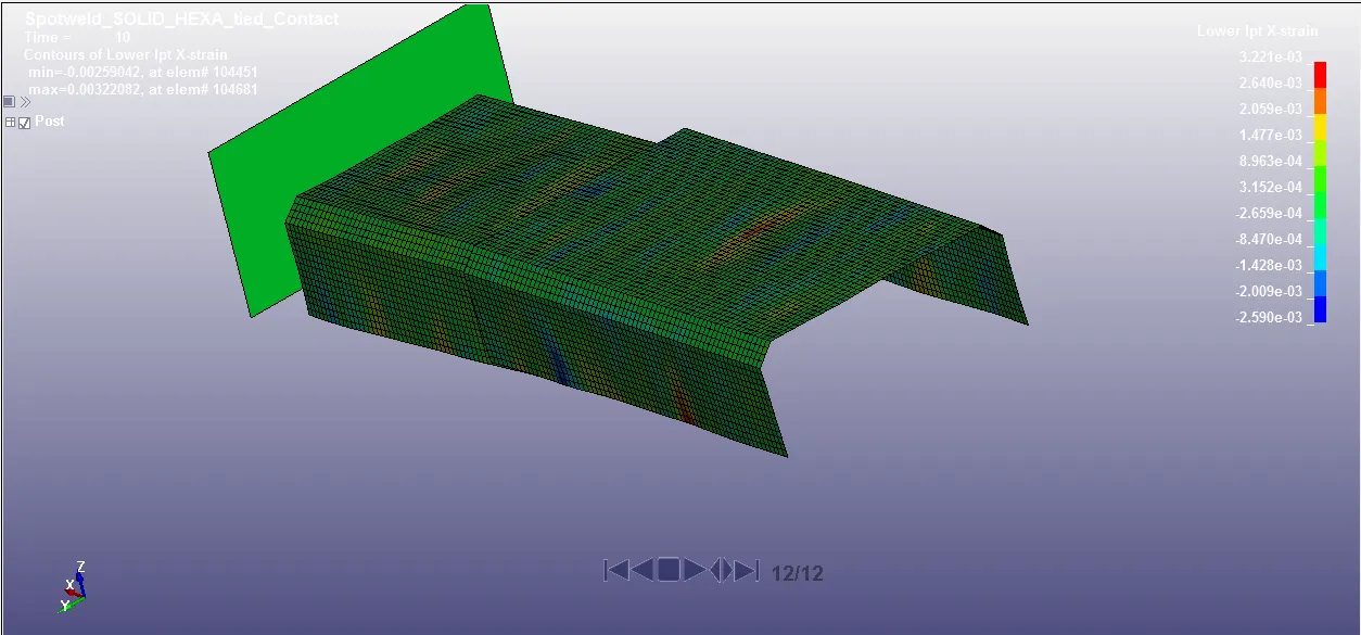
Maximum X- directional strain obtained by beam and solid spotweld at end of simulation 10 ms is 0.00643 and 0.00322 .
Strain along Y direction
During impact at 2 ms,
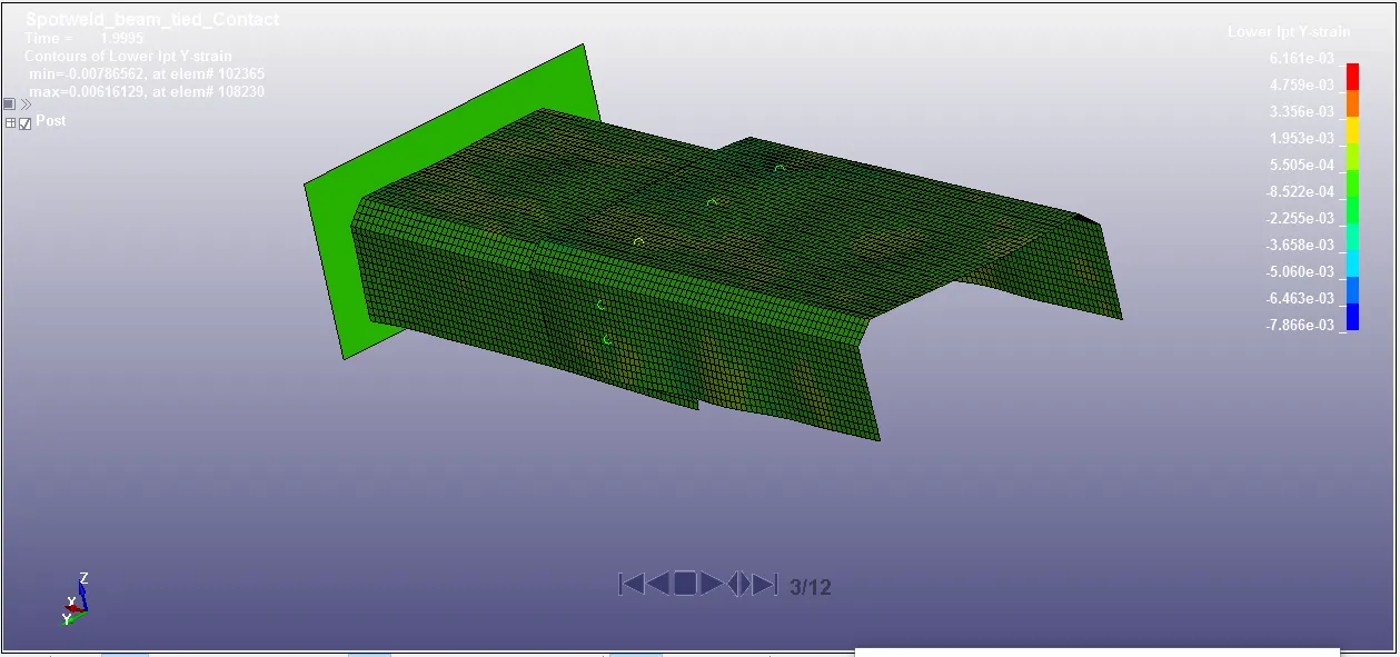
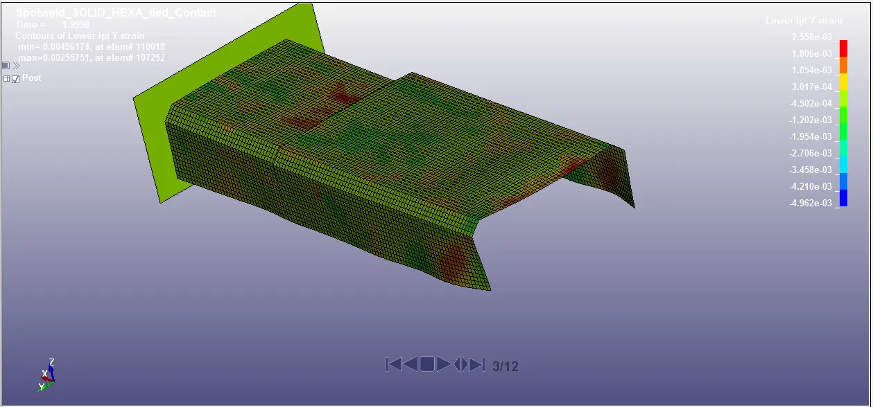
Maximum Y- directional strain obtained by beam and solid spotweld at instant of impact 2 ms is 0.006161 and 0.002558 .
Just before failure of spotweld at 4.99 ms,
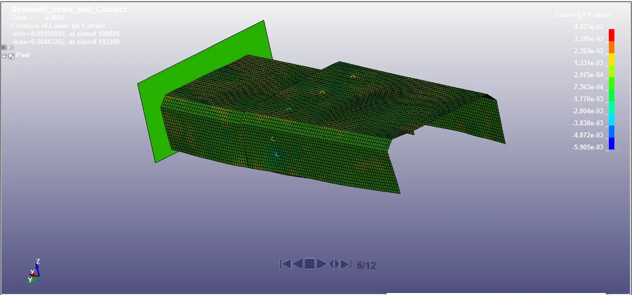
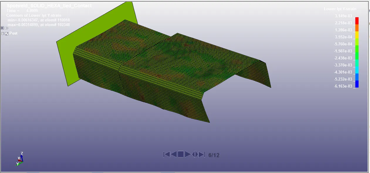
Maximum Y- directional strain obtained by beam and solid spotweld at just before spotweld failure 4.99 ms is 0.004433 and 0.003149 .
Just after failure of spotweld at 5.99 ms,
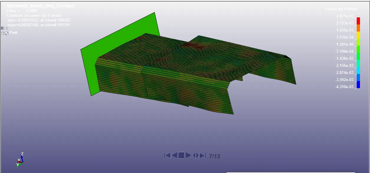
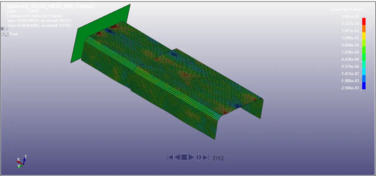
Maximum Y- directional strain obtained by beam and solid spotweld at just after spotweld failure 5.99 ms is 0.002871 and 0.002641 .
At the end of simulation at 10 ms,
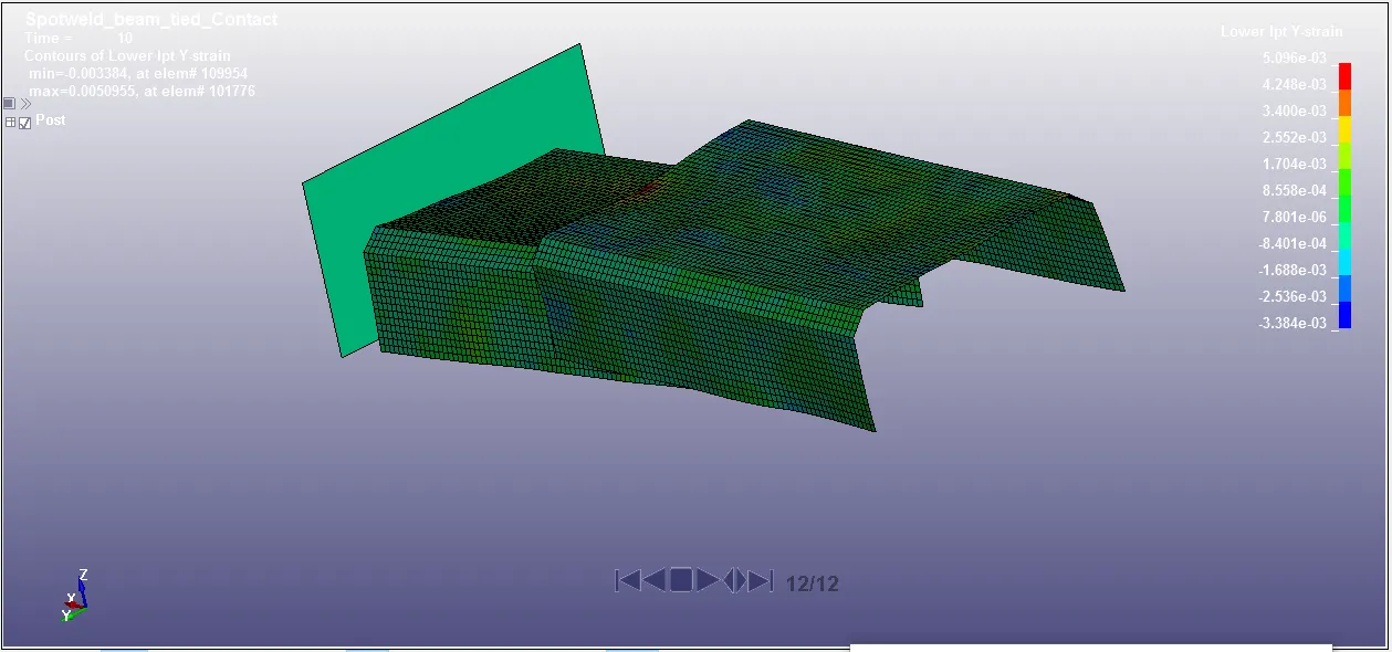
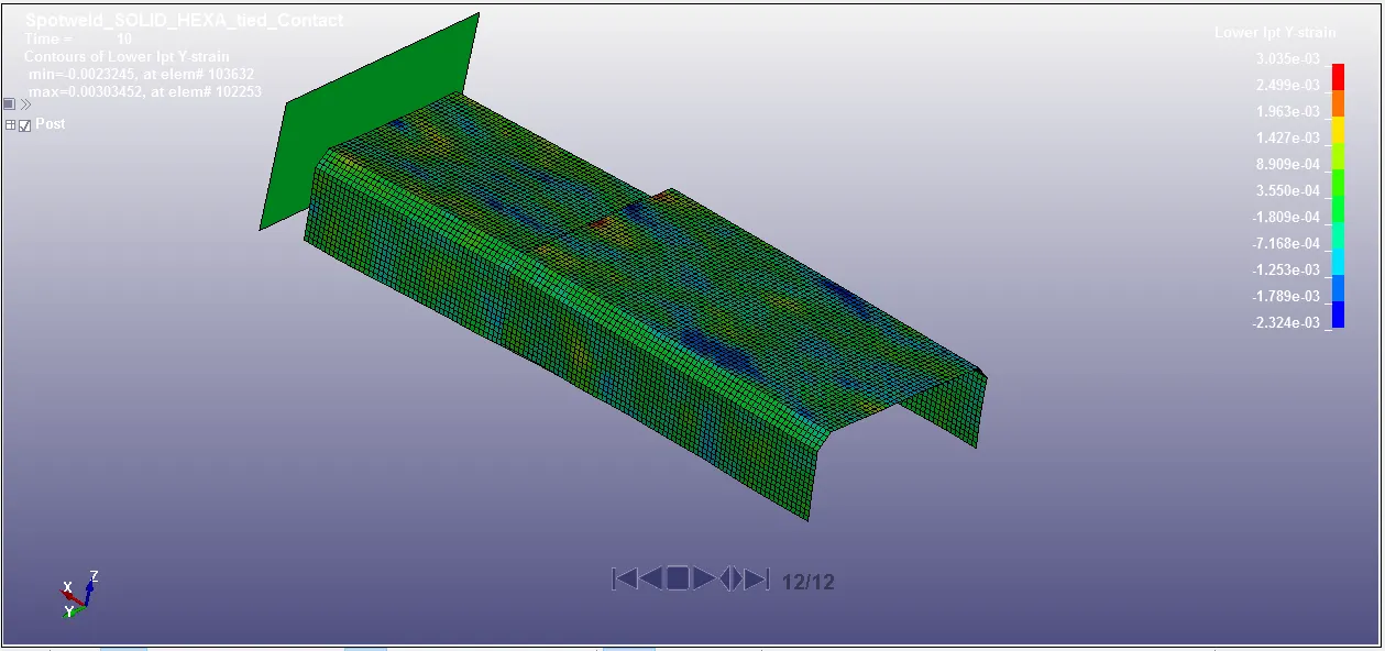
Maximum Y- directional strain obtained by beam and solid spotweld at end of simulation 10 ms is 0.005069 and 0.003035 .
GLSTAT Data:
For Beam spotweld,
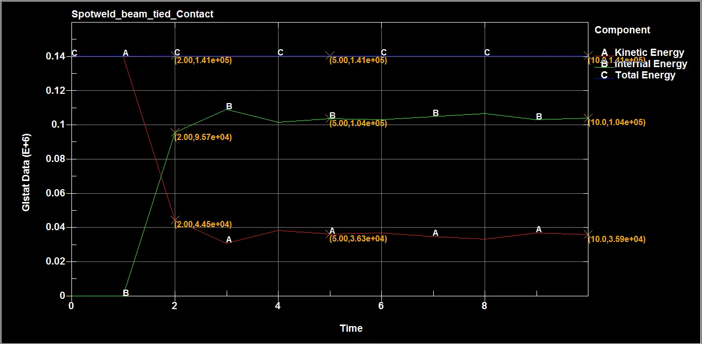
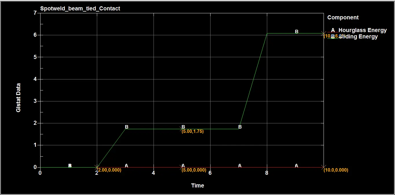
Table with data:
| Parameters | At instant of impact 2 ms | At failure of spotwelds 5 ms | At end of simulation 10 ms |
| Kinetic energy J | 4.45e+04 | 3.63e+04 | 3.59e+04 |
| Internal energy J | 9.57e+04 | 1.04e+05 | 1.04e+05 |
| Total energy J | 1.41e+05 | 1.41e+05 | 1.41e+05 |
| Hourglass energy J | 0.0000 | 0.0000 | 0.0000 |
| Sliding energy J | 0.0000 | 1.75 | 6.09 |
For Solid spotweld,
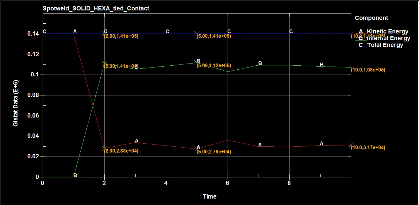
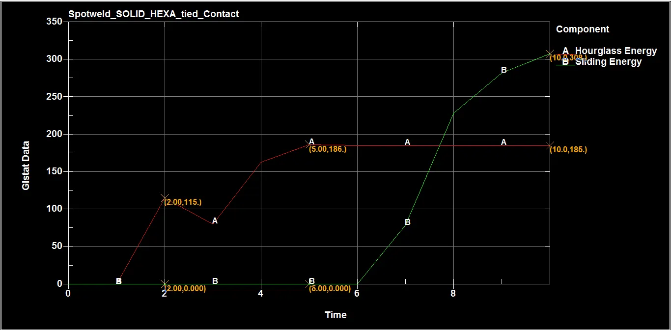
Table with data:
| Parameters | At instant of impact 2 ms | At failure of spotwelds 5 ms | At end of simulation 10 ms |
| Kinetic energy J | 2.83e+04 | 2.76e+04 | 3.17e+04 |
| Internal energy J | 1.11e+05 | 1.12e+05 | 1.08e+05 |
| Total energy J | 1.41e+05 | 1.41e+05 | 1.41e+05 |
| Hourglass energy J | 115 | 186 | 185 |
| Sliding energy J | 0.0000 | 0.000 | 308 |
The above figures are making sense,as soon as the model makes its contact with the Rigid wall , the kinetic energy is reducing to a large extent and the internal energy is rising high as the kinetic energy is converted into the internal energy. As obeyed by the Energy conservation law ,the total energy remains constant. Since we have used the fully integrated shell elements the hourglass energy is zero. The kinetic energy imparted due to the velocity of model on rigid wall got transffered to internal energy to some extent and some amount of enrgy left with the model as KE which is used for the rebounding to happen.
Conclusion:
| Parameters | Beam elements | Solid Hexa elements |
| Axial force N | 2.62e+03 | 621 |
| Shear force N | 3.43e+03 | 3.62e+03 |
The beam here is analogous with a Hair Fibre as it is very thin member (Height to diameter ratio). In here beam has been given some thickness which is less when compared to its thickness. So, it tensile resistance is maximum. That is why, the Axial force of beam elements in more than solid elements. It can also be compared to the plane stress and plane strain criteria. The ductile material is weak in shear, but it not the problem as beam and solid elements are set to 'steel'. It is the thickness that matters. The width and thickness of the solid elements are observed to be 3.5mm(approx.) which the Beam element lacks which indicates that the Solid elements are more preferable when there is any uncertainty of which element to be considered. The Failure of all the elements both beam elements and the solid elements at half the termination time i.e (5ms)