Week - 5 - Modelling Spotwelds
TITLE: MODELLING OF SPOT WELD AND RUNNING A CRASH SIMULATION.
OBJECTIVE: To run a simulation by creating spot welds between two plates and rigd wall.
SPOT WELD: Spot welding (or resistance spot welding) is a type of electric resistance welding used to weld various sheet metal products, through a process in which contacting metal surface points are joined by the heat obtained from resistance to electric current.
Spot weld can fail in two completely distinct modes, namely, nugget pullout failure and interfacial failure. These two failure mechanisms compete each other and failure of a spot weld occurs as one of the failure criterions is first satisfied.
PROCEDURE:
- UNIT USED gm mm ms
- Weld creation Beam/Solid
- Matrial assigin to the weld.
- Section created for the weld.
- Boundary conditions applied.
- contact defination.
- Assigning control cards.
- Assigning Database cards.
- At first weld is created using edit element option then using two nodes one beam element in created.Rest of the welds are also created same.
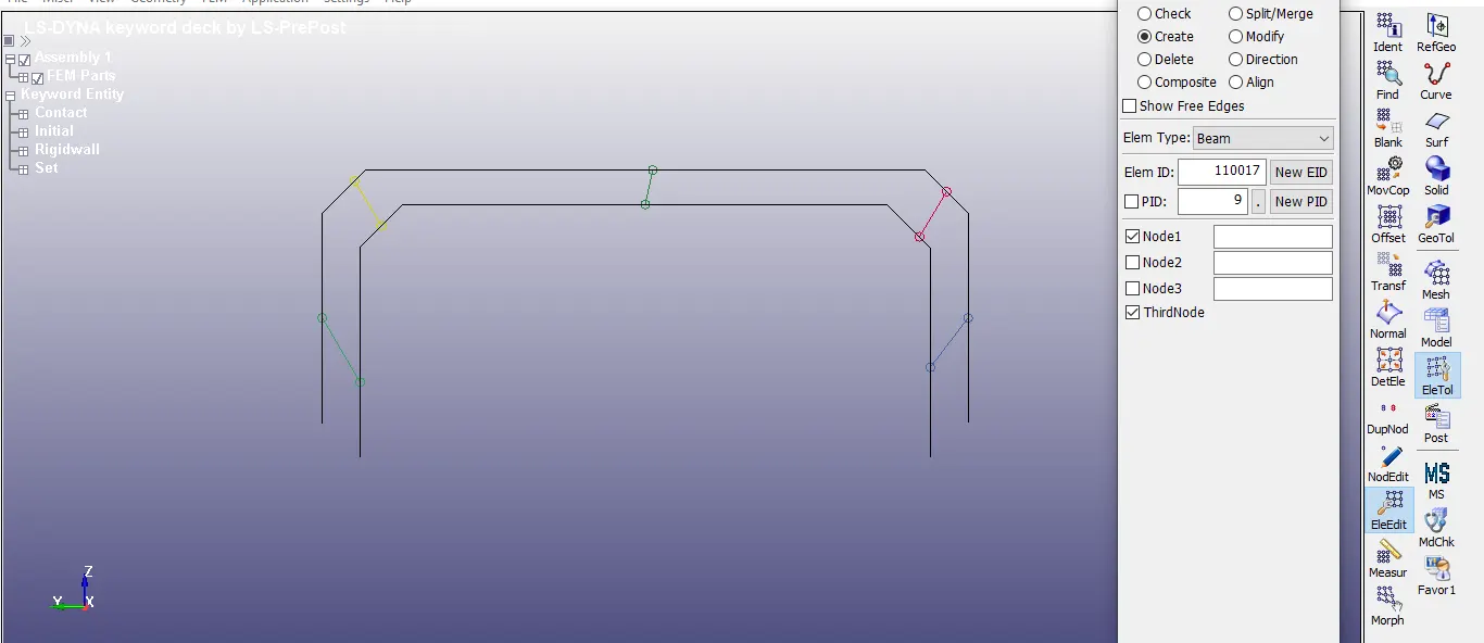
- Then Materials are assigned to the beam elements and shell parts.
- For beam element MAT100 and for Shell part MAT024 is used.
- Properties of steel are used.
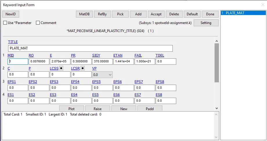
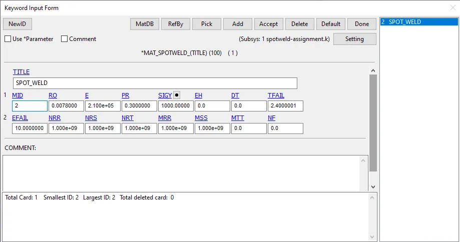
- In spot weld material failure time is mentioned for the spot weld as 2.4ms(TFAIL).
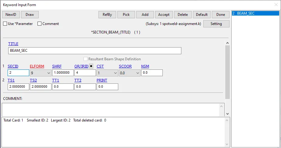
- Now defined the section card.
- For shell part element formulation used is ELFORM16 and for the beam part ELFORM 9 is used as section.
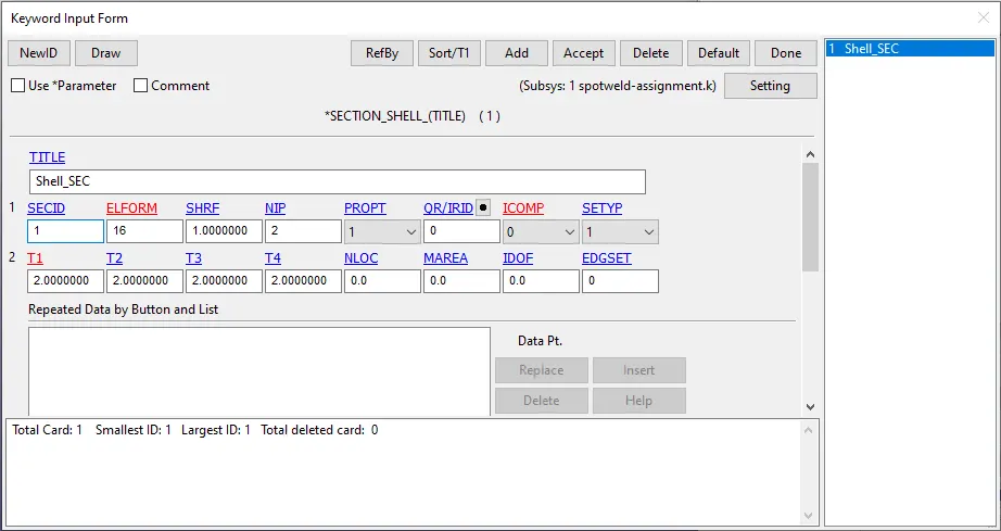
- Now boundary conditions are defined.
- Rigid wall is created at a distance of 30mm in global x direction.
- Initial velocity of 13.8889 mm/ms given to the shells in global x direction.
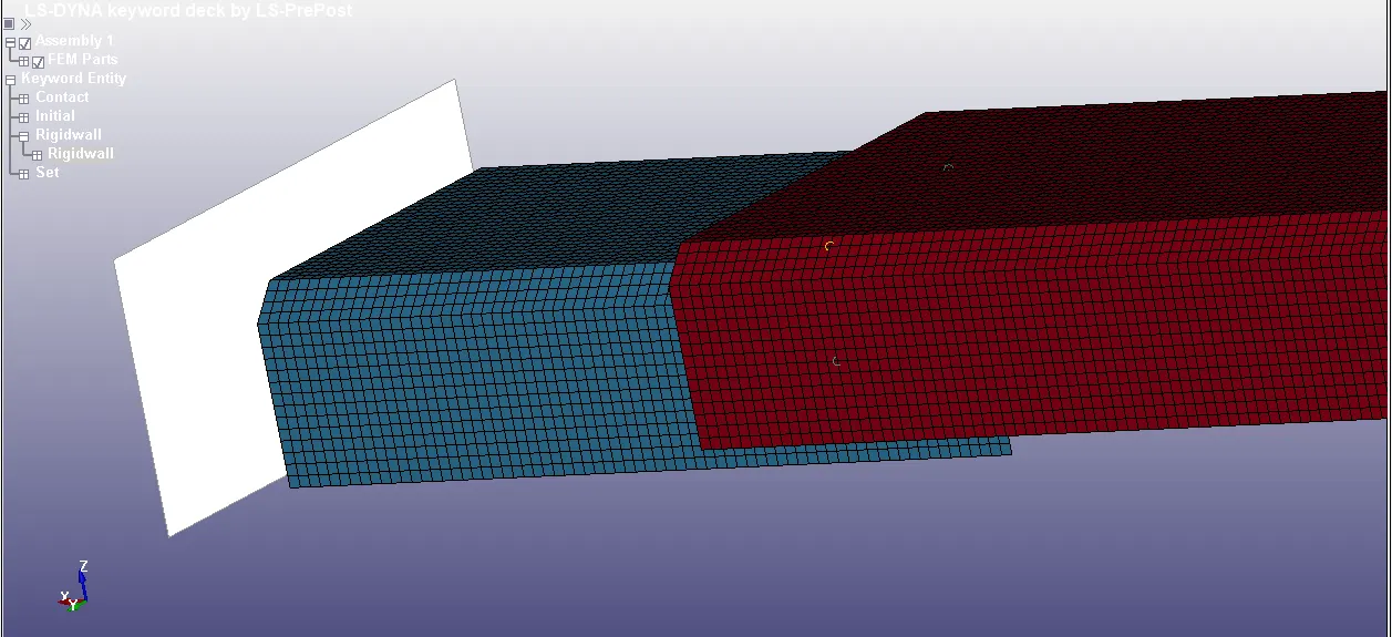
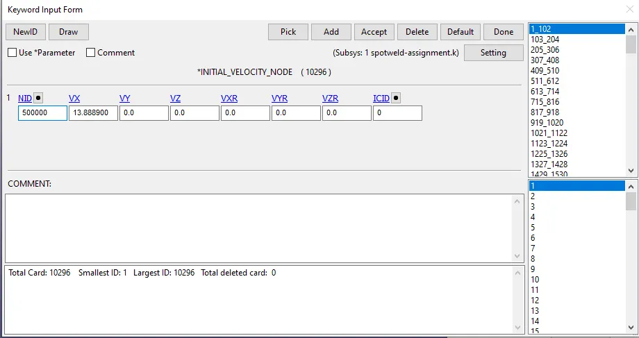
- Contacts are defined between the beam and shell elements.
- Self contact is defined between two shell elemts.
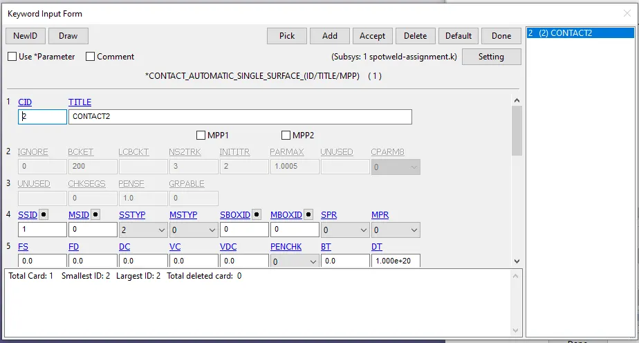
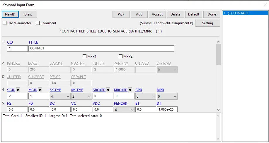
- Here contact between shell and beam elements are defined so that after failure no elemts penetrates other.
- To define the contacts set of nodes and part are to be difined and MSTYP is given as 2.So that master id is given as set of part id.
- Here master is given to shells and slave is given to the beam node set.
- Now control cards are defined.
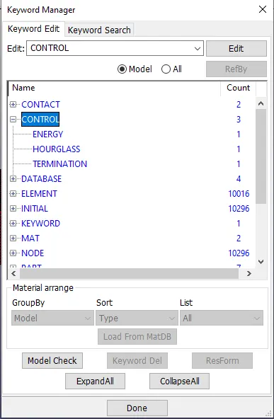
- Here control energy is used so that it conclude the hourglass in final result.
- Hourglass control is used in this simulation.
- Here terimaton time is used as 3.5ms.
- Data base cards are defined.
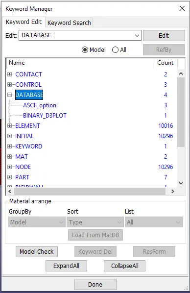
- Here ASII card is use to define the GLSTAT , SWFORC, SLEOUT.
- BINARY_D3PLOT is used to define the final results at a time interval of 0.05ms.
SOLID SPOT WELD:
In solid splot weld solid elemts are used and only there is change in contact and section card all other parametrs will be same as above.
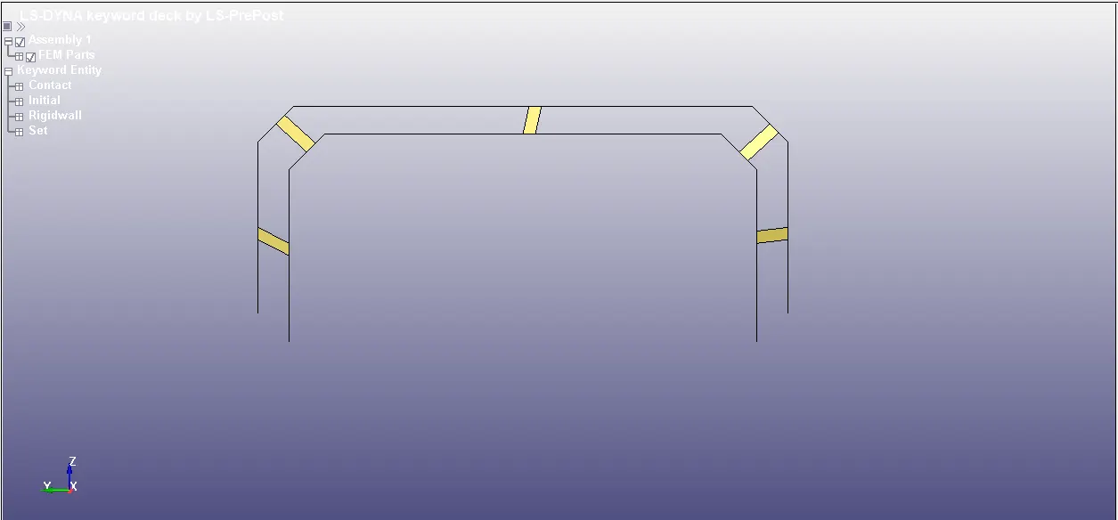
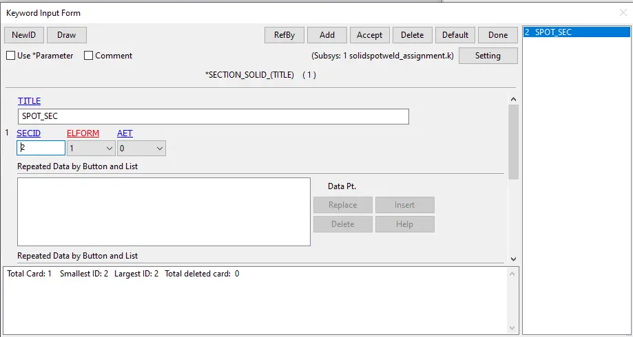
- Solid section is used with ELFORM 1.
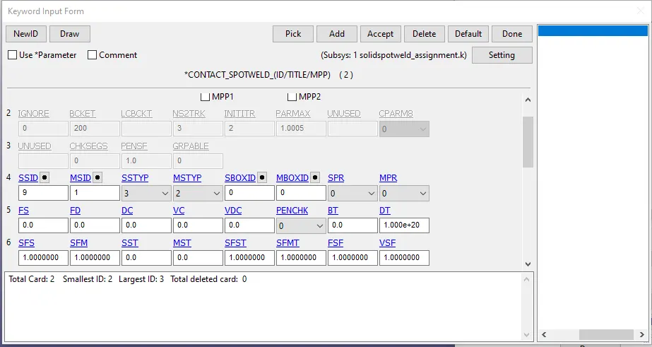
- Here contact used is spot weld contact where master is given to shell part and slave is given to solid spot welds.
RESULTS: FOR BEAM SPOT WELD.
- GLSTAT results.
- Internal energy,Kinetic energy,Total energy.
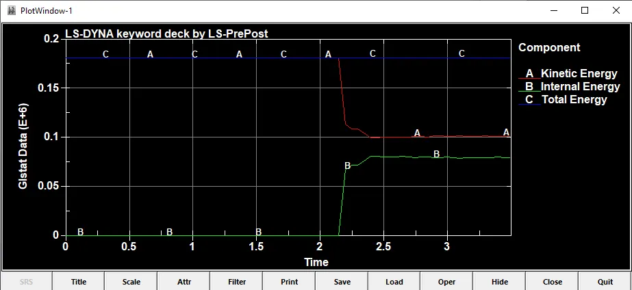
- Internal energy is assosiated with the internal molecules of the elements as we can see at 0 it is at 0 then slowly after 2ms when the crash happened its increase due to that phenomenun kinetic enegry decreases in same manner after similar time interval.Here total energy is seems to be constant.
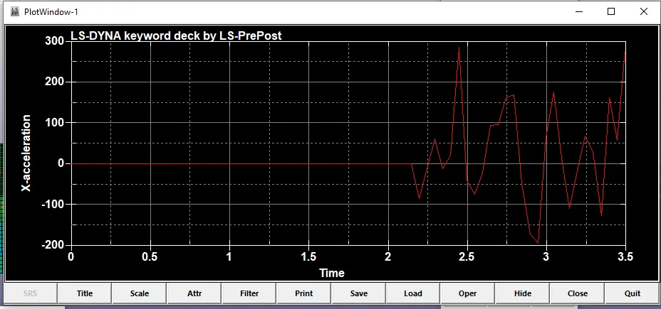
- A random node is selected at the middle point to look at the accelaration happening at that node.Therfore it was noticed that after the crash when shock waves travel after 2ms in the plates then acceleration decreases and then there is sudden increase in the slope. afterwards its fluctuating upto the end of the time interval.
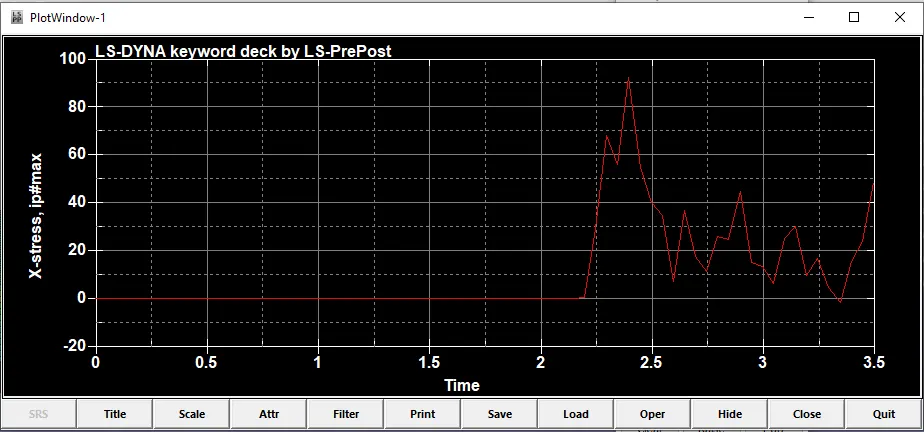
- Here x stress is seen to very high around 2.4 ms where the TFAIL is defined.So it can be seen that maximum stress on an element in seen when the spot weld is failed around 2.4ms.
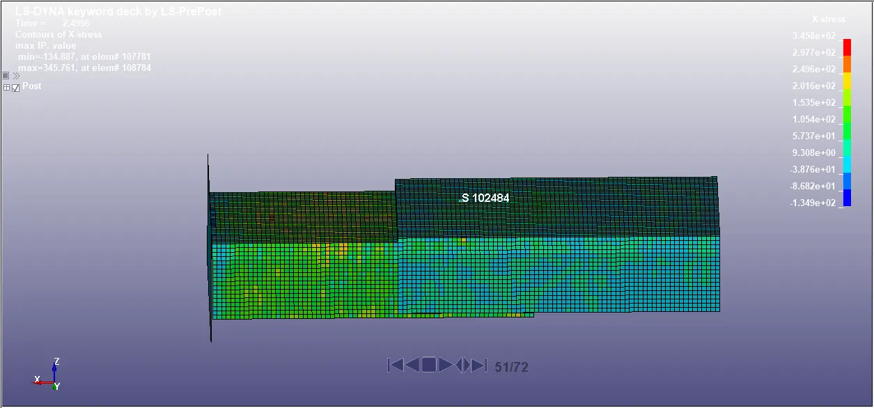
- Here we can see the contour of the model.Where x stress maximum is showing as 3.45e+02 gm.mm-1.ms-2
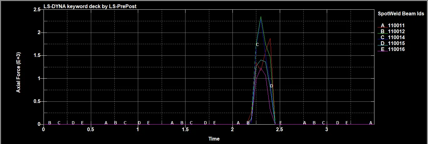
- I have defined TFAIL as 2.4ms its the time interval when the beam elements will fail.Here I can see that after 2.2ms some of elemnts are started failing and around 2.4ms maximum spotweld are failed and maximum axial force that is achived is around 2.4 e+3.There is sudden drop in the axial force due to low timestep used.Although after 2.4ms element A failed at the end of all the stop welds.
SOLID SPOT WELD RESULTS:
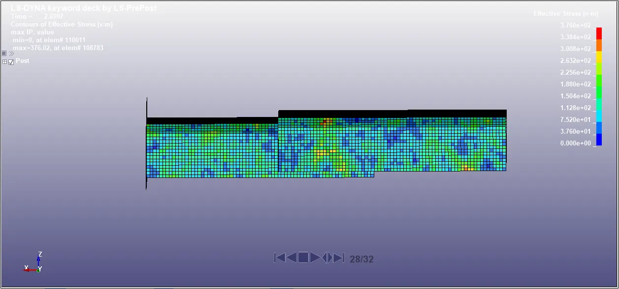
- Here we can see the contour of the model.Where x stress maximum is showing as 3.76e+02 gm.mm-1.ms-2
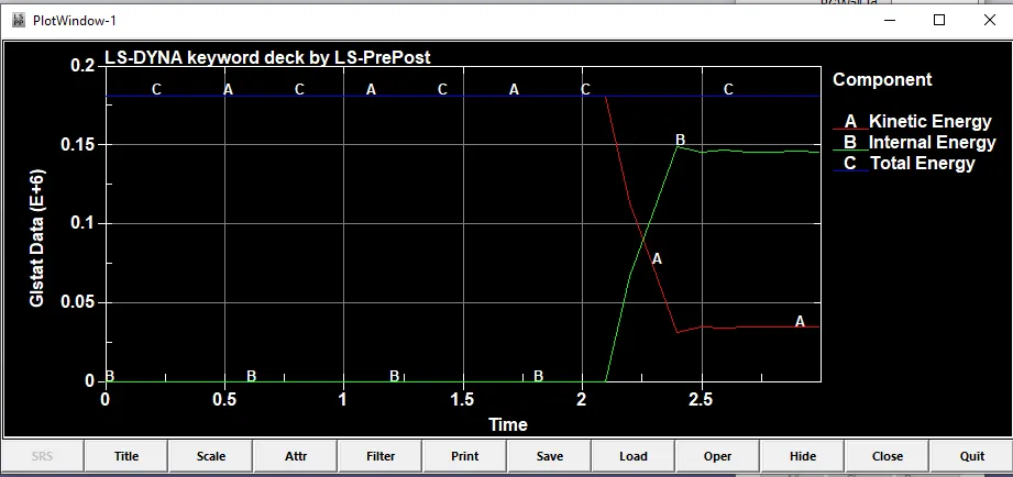
- Internal energy is assosiated with the internal molecules of the elements as we can see at 0 it is at 0 then slowly after 2ms when the crash happened its increase due to that phenomenun kinetic enegry decreases in same manner after similar time interval.Here total energy is seems to be constant.
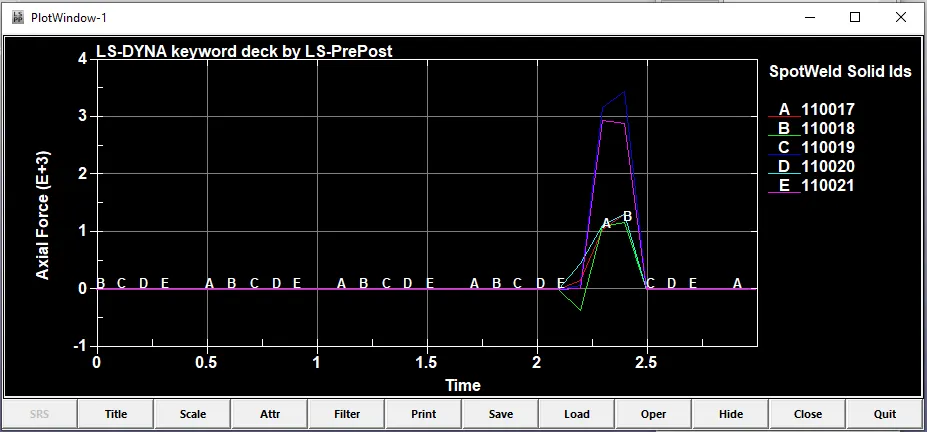
- I have defined TFAIL as 2.4ms its the time interval when the beam elements will fail.Here I can see that after 2.2ms some of elemnts are started failing but spot weld B is showing some negative force due to high impact will the rigid wall.Here the case is different then the beam spot weld as I can see elements are failing after some time and force remains due to their solid behaviour of the spot weld.Highest force is attained around 2.4ms by spotweld C.
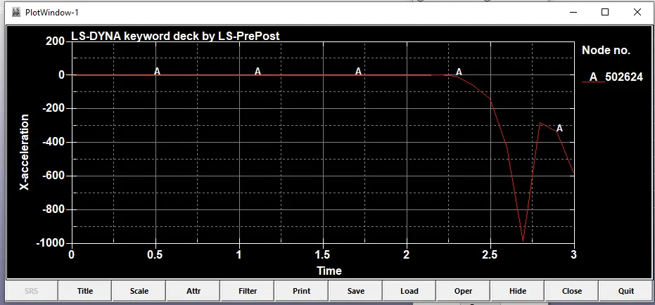
- Here the curve is going in negative accelaration as impacted by the rigid wall.
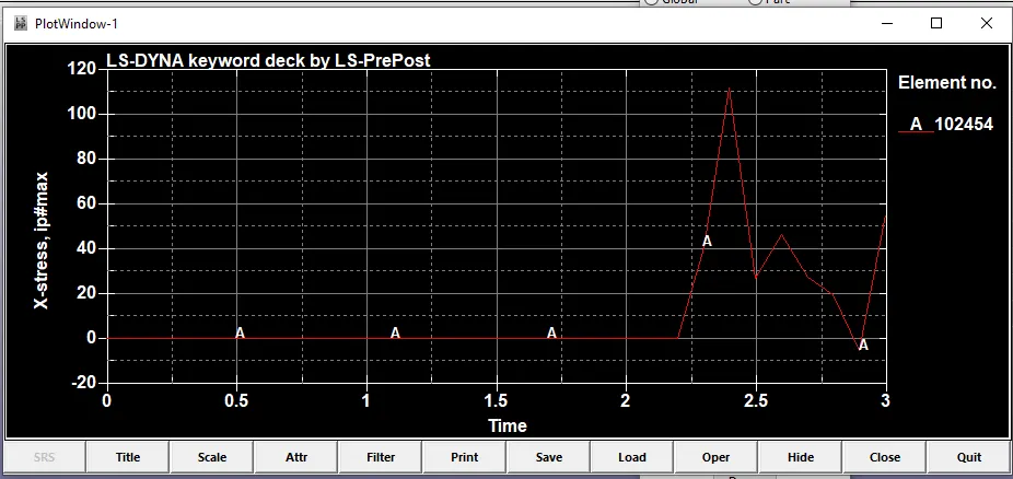
- Stress in X direction is fluctuating in nature after 2ms just after the crash as waves travels the plate all the element faces some stress on them.
CONCLUSION:
- Learnt to design the spot weld using beam and solid elements.
- Outcome as axial force is measured using a special card in ASCII i.e SWFORC.
- Time at which spot welds are failed calculated after one trial of simulation.