Week - 5 - Modelling Spotwelds
Spotweld Crash Analysis Performed with Beam and Solid Element in Ls-Dyna,
Objectives;
The main objective of the project model the spotweld with beam and solid elements, and perform the crash analysis test then compared the results in different parameters like,
1. Axial and shear forces of the beam and solid elements and Maximum directional stress and strain along the longitudinal axis.
2. Cross-sectional force at midplane and Acceleration of a node at the midplane and the Energy plots.
Procedure;
Welding is a fabrication process whereby two or more parts are fused using heat, pressure, or both forming a join as the parts cool. Welding is usually used on metals and thermoplastics but can also be used on wood. The completed welded joint may be referred to as a weldment.
Modeling the beam element,
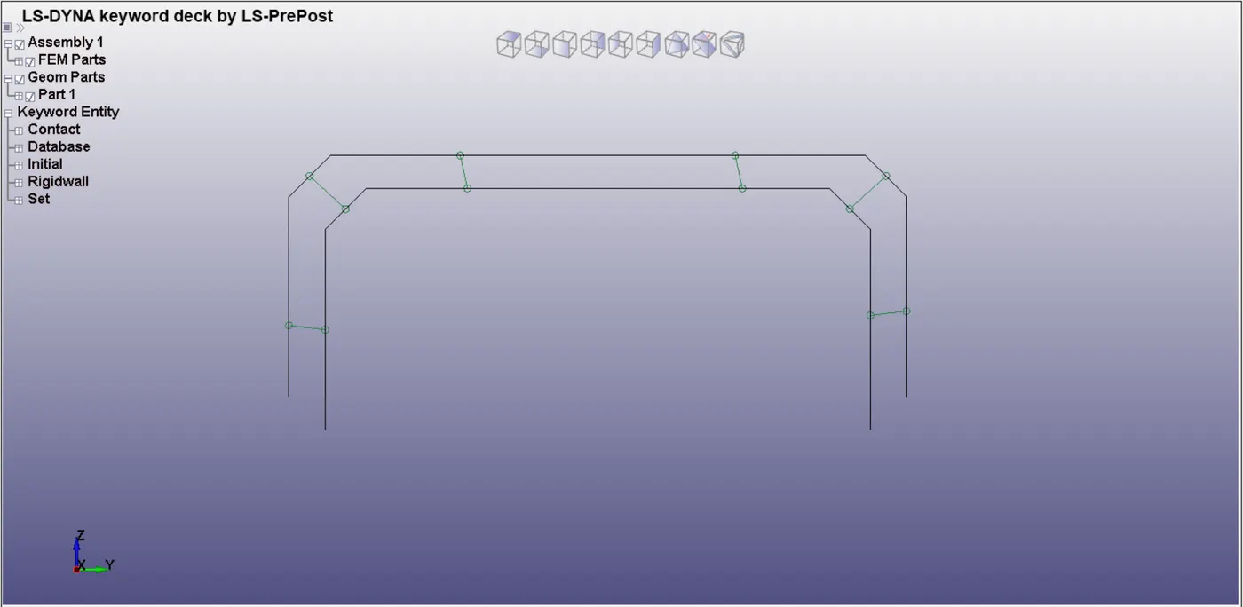
To Create the beam element by using the Element tool>Element editing. It refers to the element ID and Part Id definition.
Material Creation,
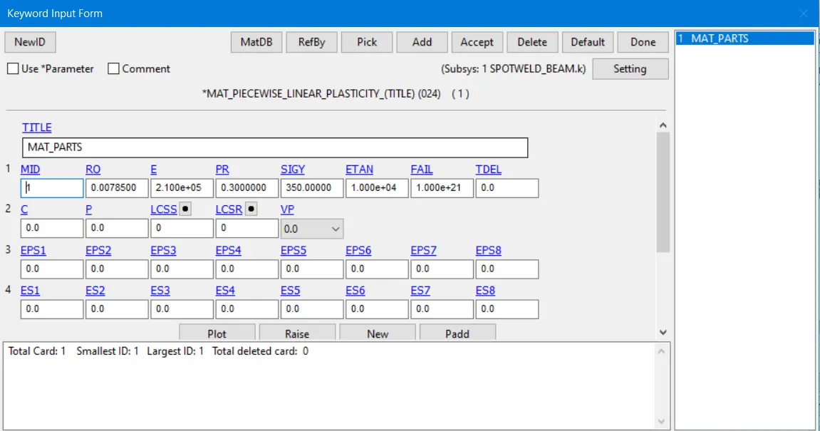
The two material cards created, where MAT024_Linear_Piecewise_Linear_Plasticity for that two parts shell elements, and MAT100_SPOTWELD for beam element.
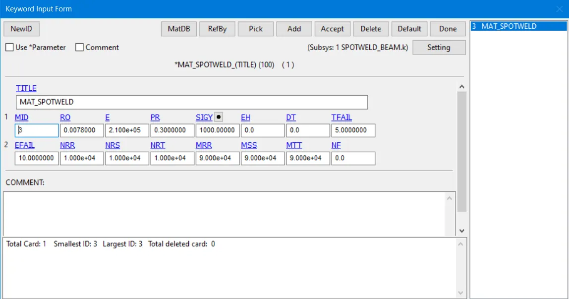
Spotweld is a steel material its base failure occurs at 5ms. It is mentioned at TFAIL=5.
Section Creation,
Two section cards were created, SECTION_BEAM this one is elements, and SECTION_SHELL this one is for shell elements.
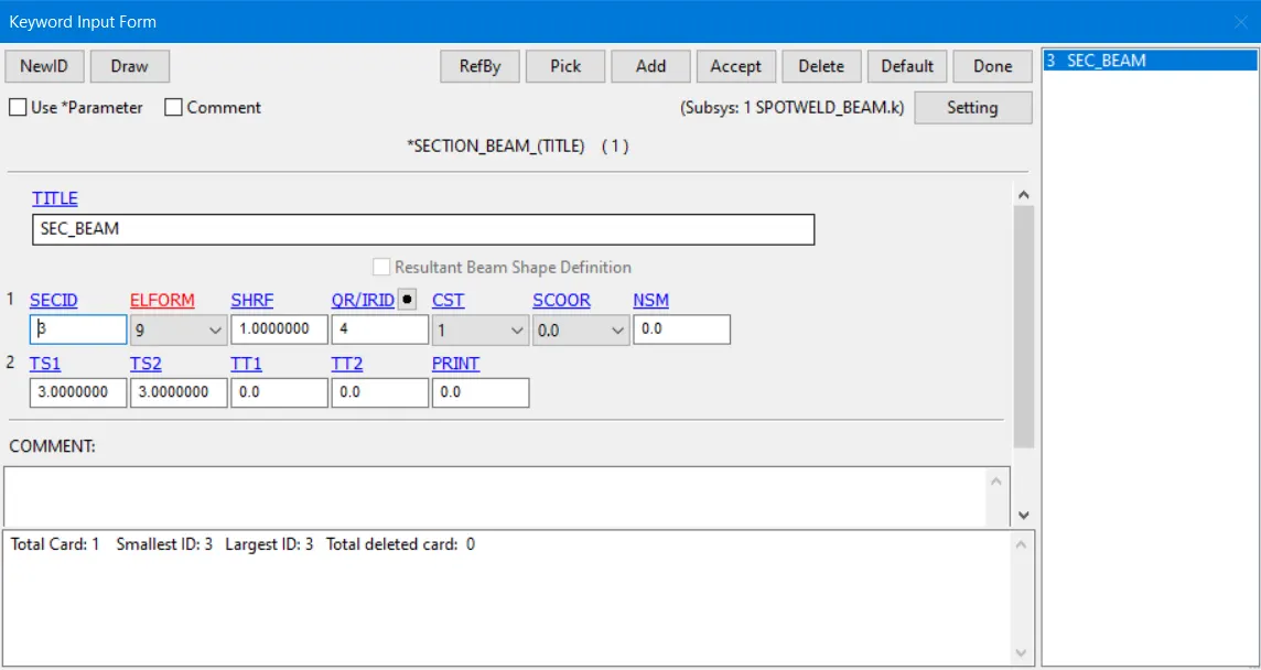
where the ELFORM is 9 for beam because the beam MATT_SPOTWELD type is 10 and QR/IRID is 4 and the thickness of the beam is 3.
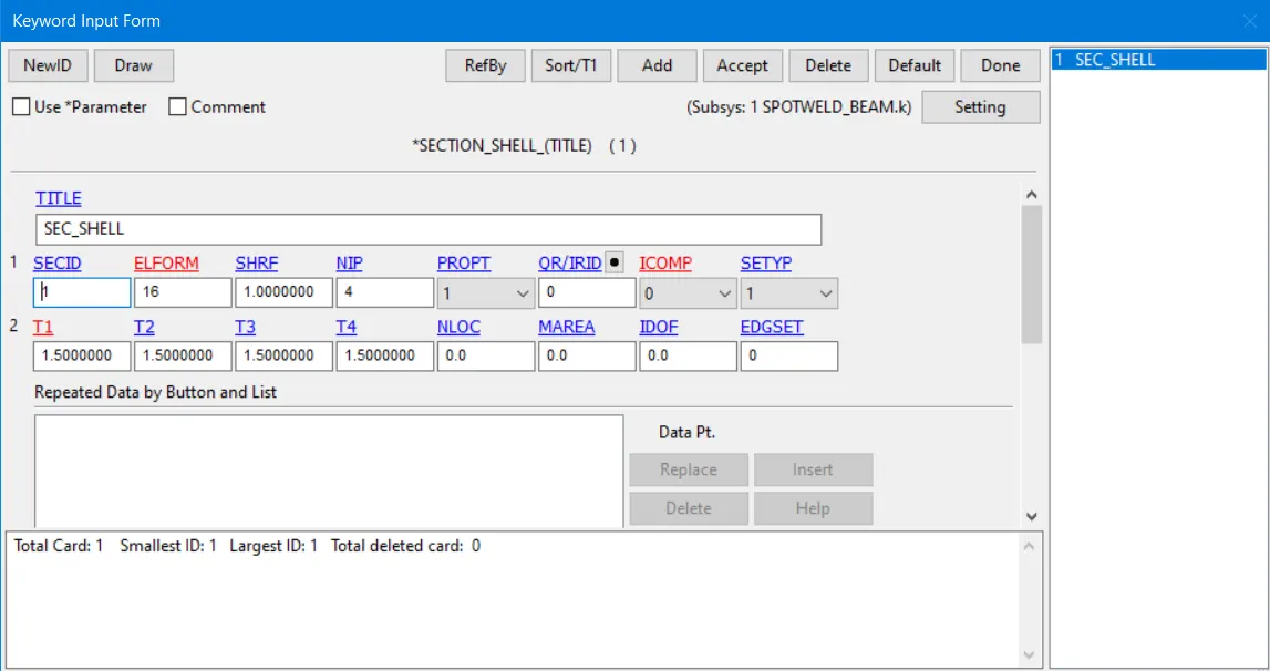
Where the ELFORM is 16 for the Shell element because formulation 16 is the fully integrated and thickness of the shell is 1.5.
Part Creation,
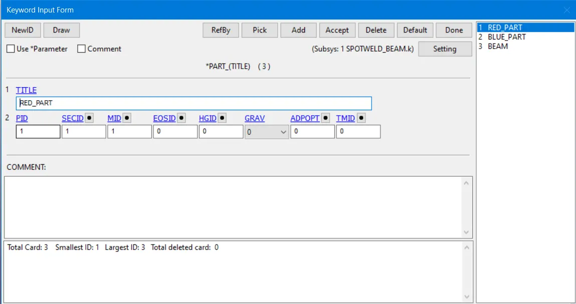
Assign the material card and section card to Pard ID.
Contact Creation,
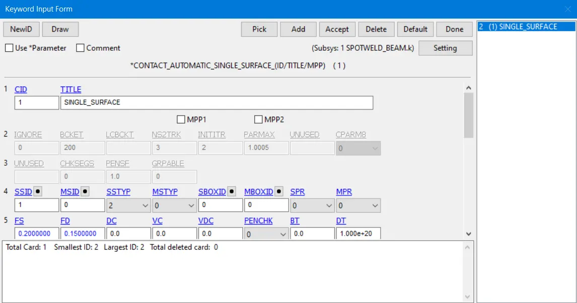
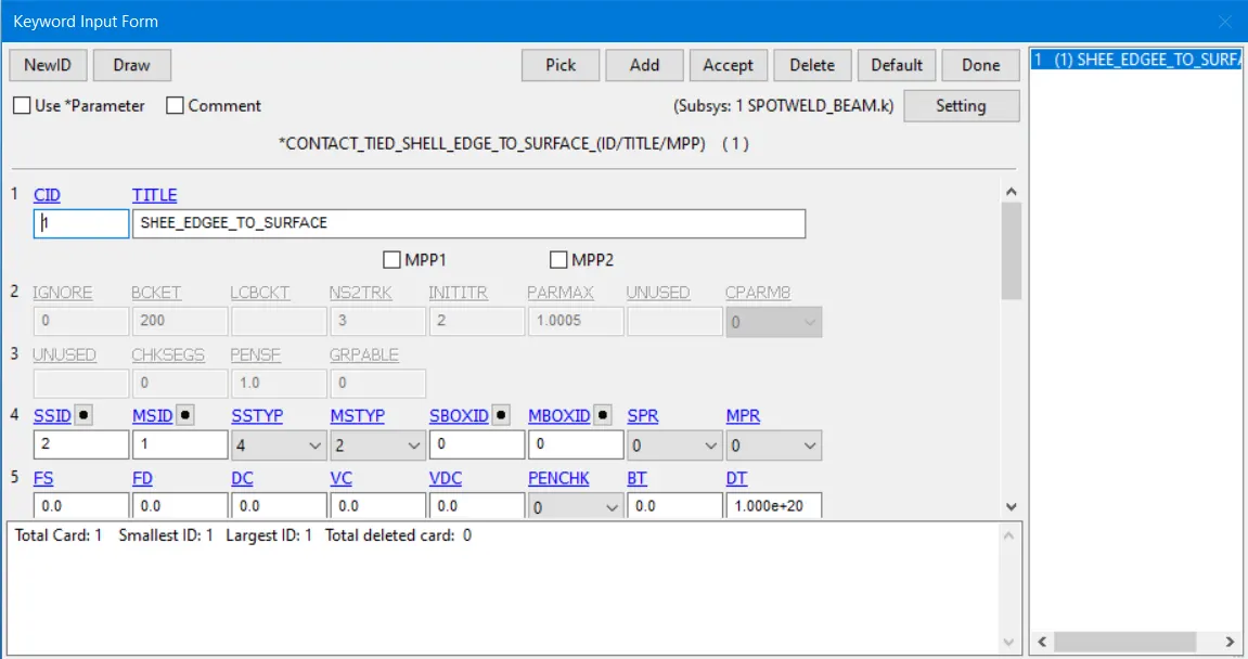
In contacts, Automatic_Single_Surface Contact for Shell parts because, when the spotweld beam fails don't penetrate to each other so this contact is used here. And the Tied_Shell_Edge_To_Surface Contact used to between the Shell parts and Beam Elements.
Beam Elements are considered the slave id and Shell pards are considered the master id.
Rigid wall,
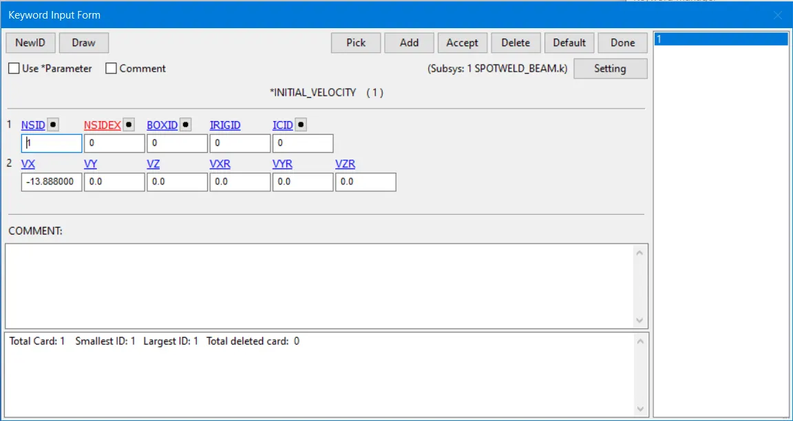
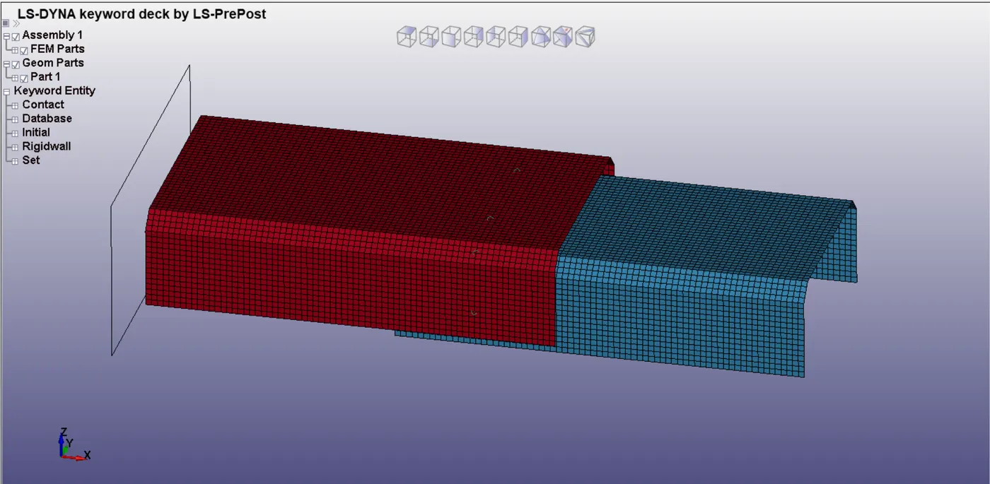
The rigid wall created some particular distance from the shell parts, and Initial velocity also gave 13.888 to shell parts towards the rigid wall.
Control Termination,
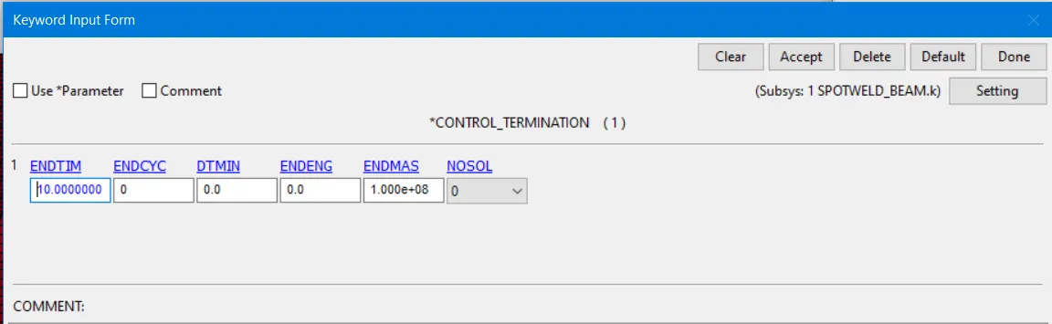
Termination time has 10ms imputed to the control card. And also mentioned the Control_Energy and Hourglass in the control card.
Database Creation,
Binary_D3 plot was created with the time interval given as 1ms.
ASCII option- GLSTAT, MATSUM, NODOUT, SECFORC, SLEFORC, SWFORC have been created at DT-1ms.
History Node of beam elements has been selected for the acceleration of nodes at the mid-plane.
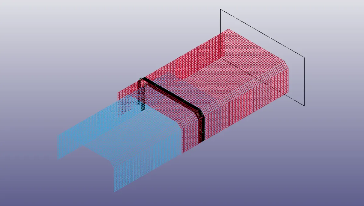
Cross-section-Set at the midplane of the cross-section and shell elements and where the nodes of the beams have an intersection between have been selected.
Here, we can find out the result of the two methods. one is the Timebase methods and another one is force base method. TFAIL= 5 (Timebase) when you create the weld sometimes its difficult that exit force required to break the weld might not generate in CAE analysis. you can give the time as the failure time. For example, If your simulation is running for 50ms. see that 50ms welds are failing so you can give the 50ms.
TFAIL = Failure time
NRR, NRS, NRT = This three-parameter is the kind of force.
MRR, MSS, MTT = This three-parameter is the kind of moment. This parameter used to show the force and moment criteria for the weld and how did it fail and real-life weld analysis used to above the six parameters.
Results;
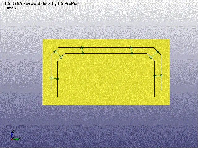
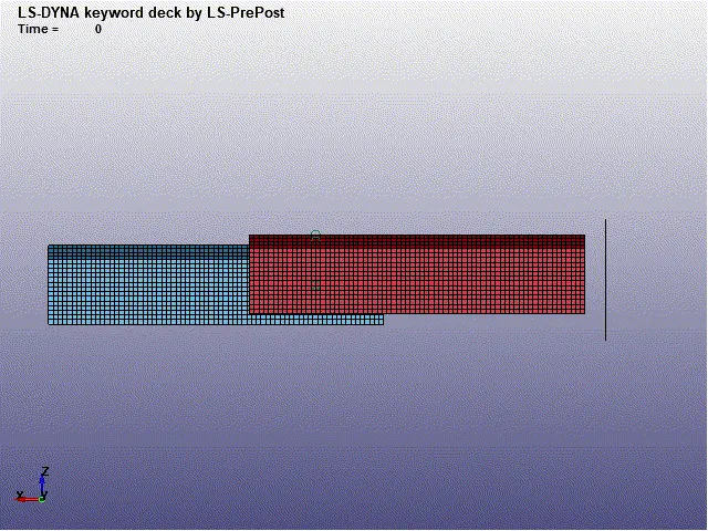
1. Axial Force of Spot weld Beam,
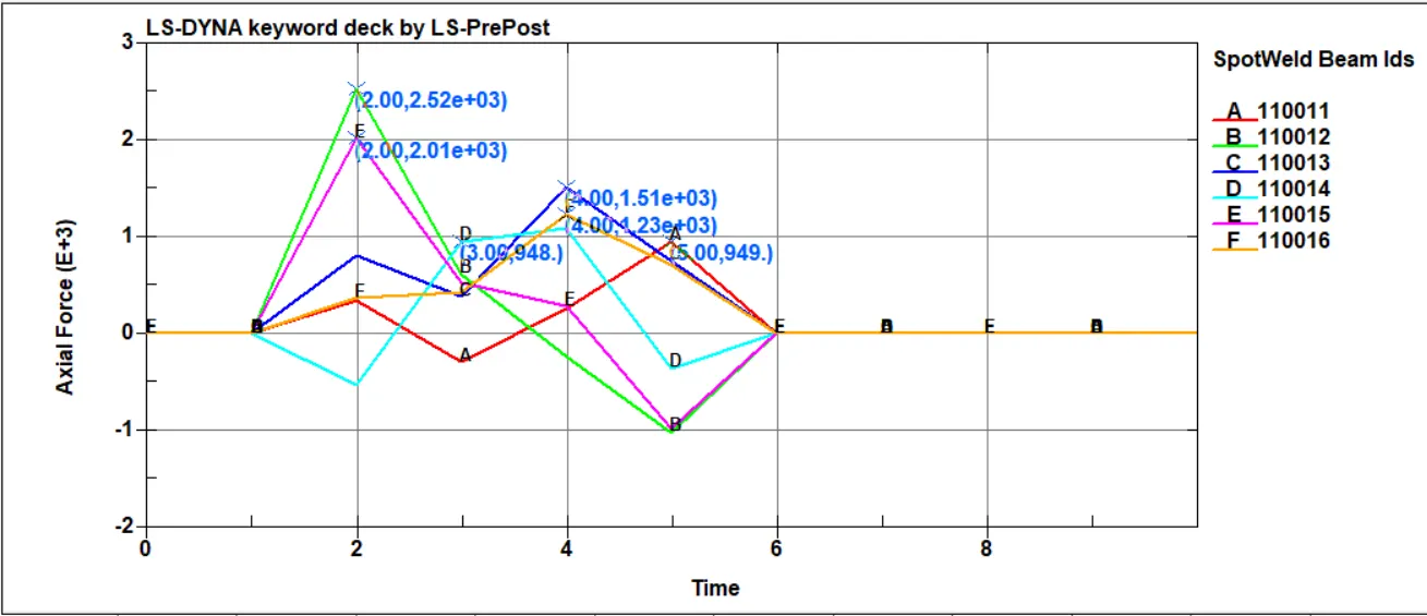
The maximum axial force identified at 110012 beam element with force 2.52e3N takes place at 2ms.
2. Shear force of Spot weld beam,
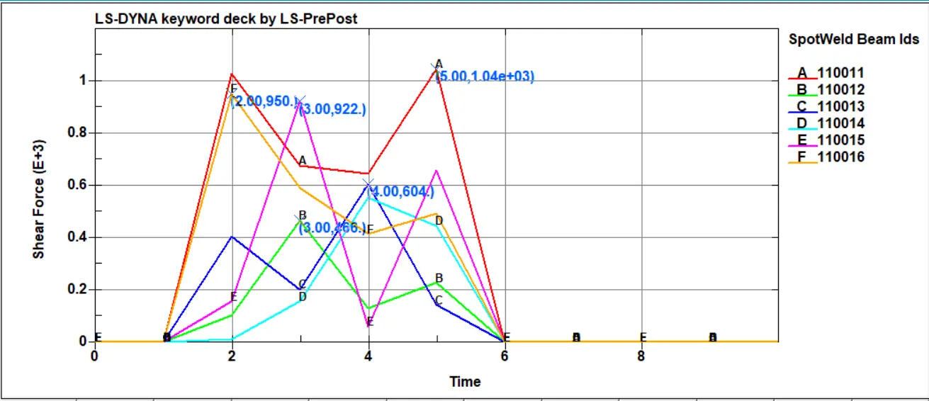
The maximum Shear force identified at 110011 beam element with force 1.04e3N take place at 5ms
3. Cross-sectional force at midplane for beam element,
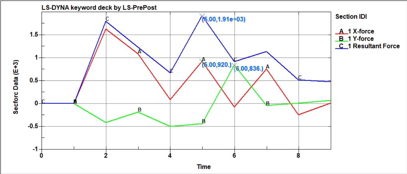
The maximum cross-sectional forces 1.913e-3N in 5ms via Resultant force, and X force and Y force occurs in the cross-sectional area.
4. Acceleration X direction of the node at midplane for beam element,
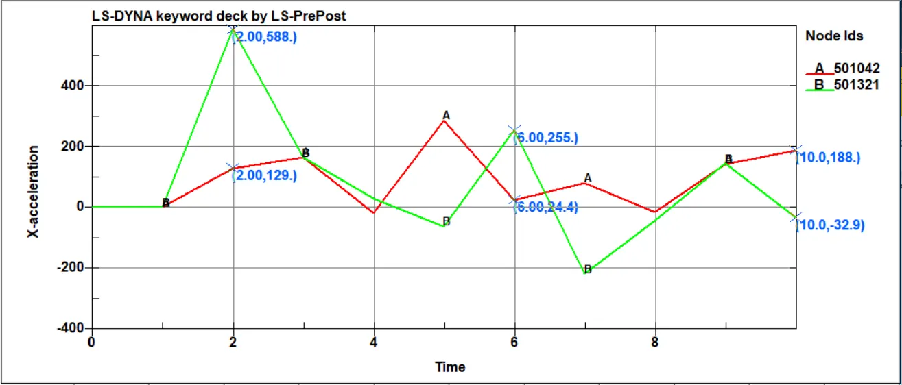
The maximum acceleration occurs in the X direction of the nodes at the midplane for beam element 24.4mm/ms2 at 6ms.
5. Acceleration Y direction of the node at midplane for beam element,
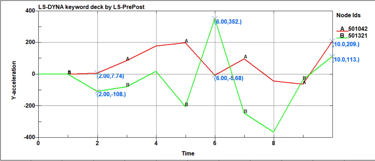
The maximum acceleration occurs in the Y direction of the nodes at the midplane for beam element 5.68mm/ms2 at 6ms.
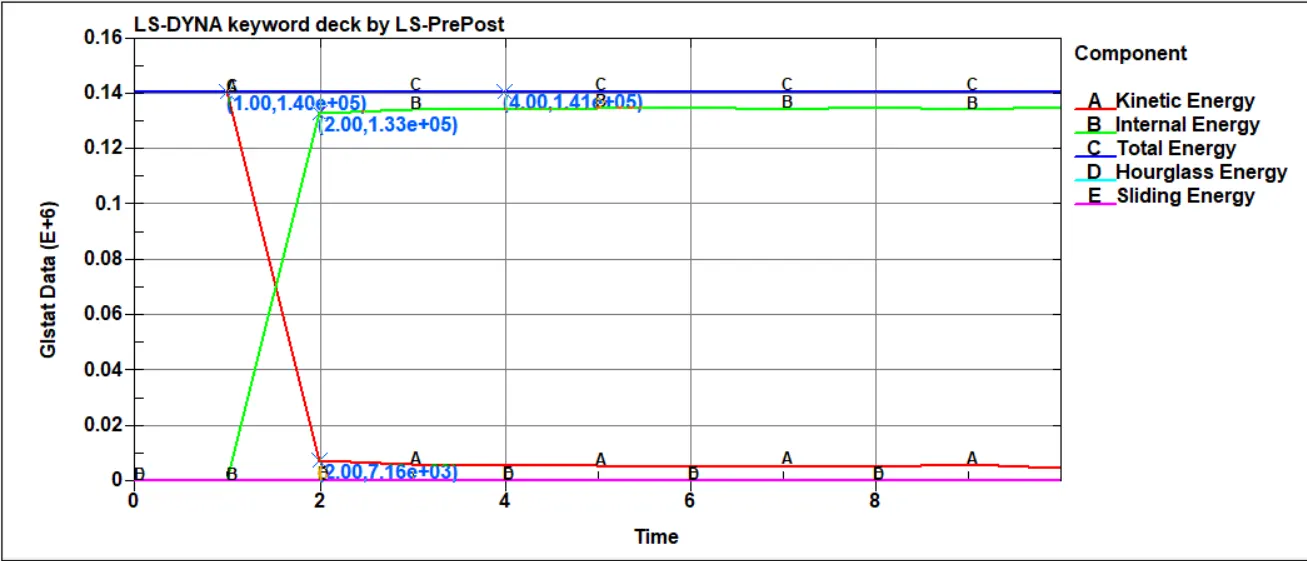
6. Energies for beam element,
7. Stress along the longitudinal axis,
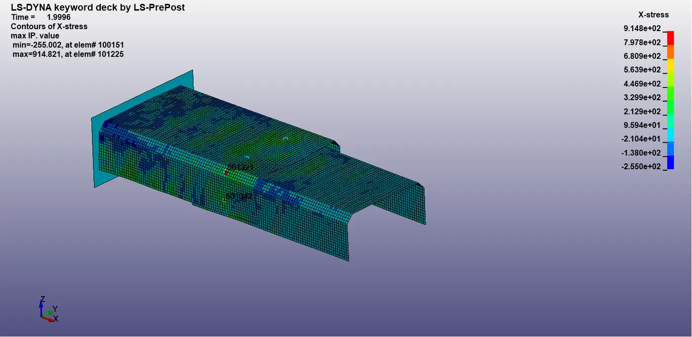
the maximum stress at the time of failure 9.148e2
8. Strain along the longitudinal axis,
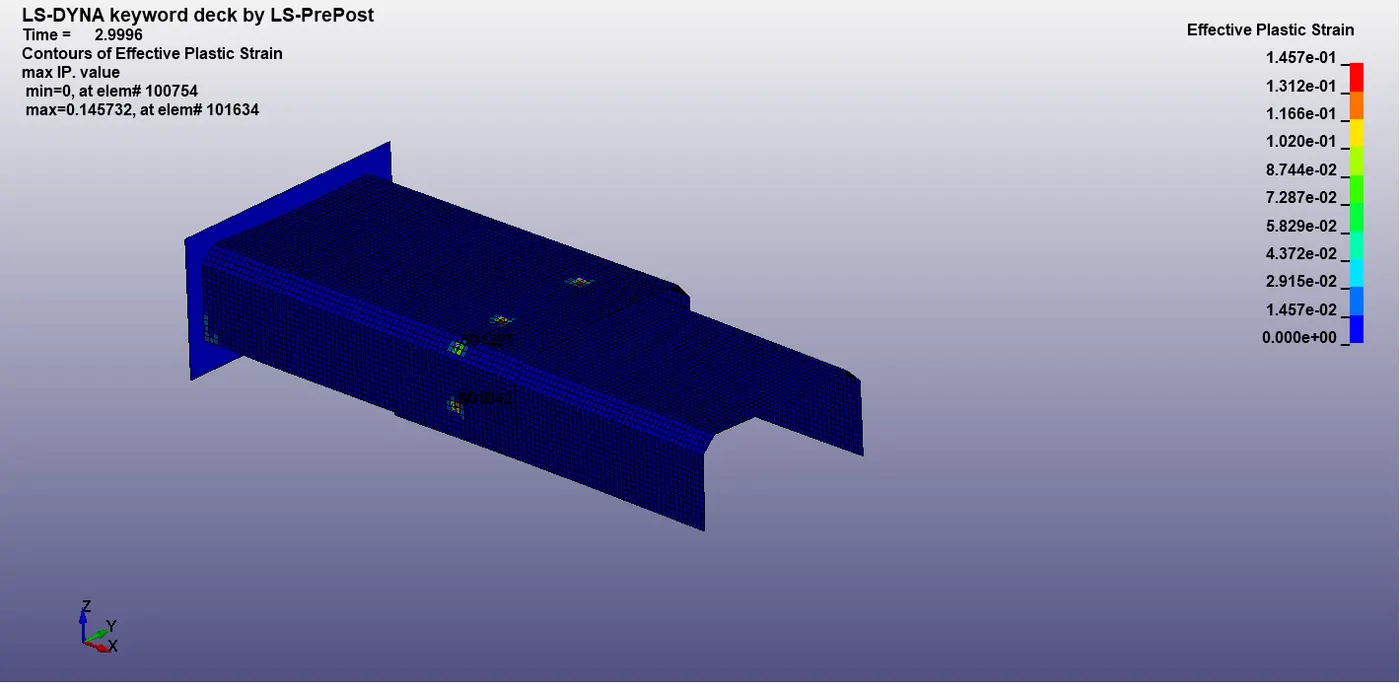
the maximum strain at the time of failure 1.45e-1
Spotweld For Beam Element;
Everything as the same as to the beam element, but change the element type to Hexa solid and select the nodes.
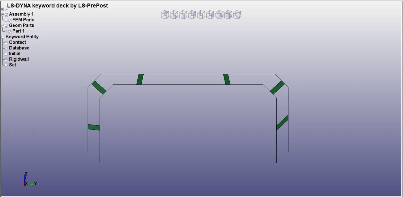
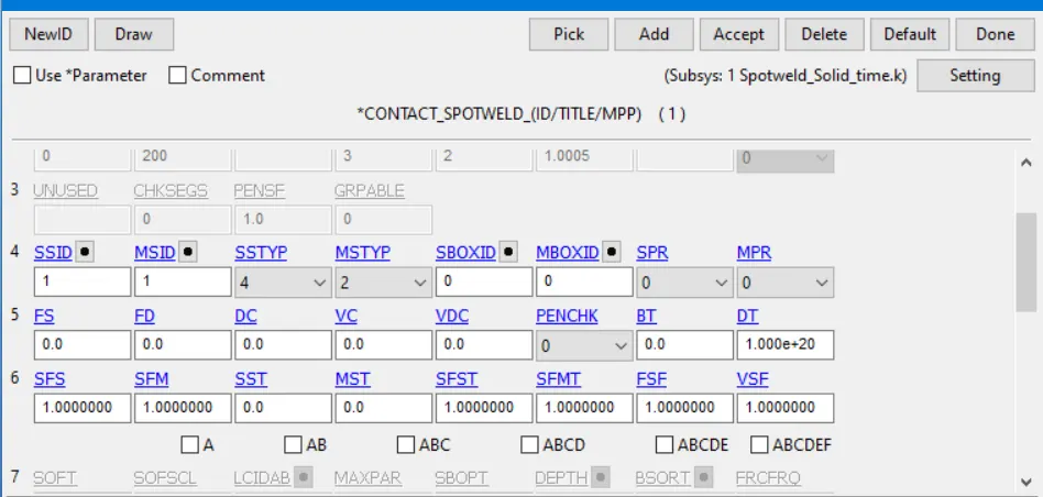
Change the section solid ELFORM is 1 and create it. And take the contact for solid elements as CONTACT_SPOTWELD and set the slave type for solid elements nodes and assign them, slave, while shell as a master type and assigning them for the master.
Node set and shell elements for the cross-section set to obtain the cross-sectional forces.
Results,
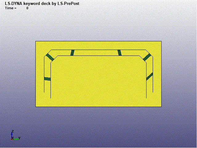
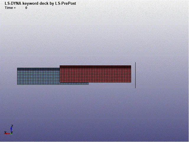
1. Axial Force of spot weld for Solid element,
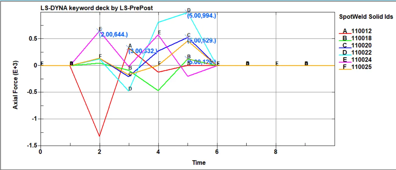
The maximum axial force identified at 110022 beam element with force 994N takes place at 5ms.
2. Shear Force of spot weld for Solid element,
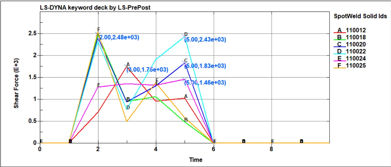
The maximum axial force identified at 110022 beam element with force 2.43e3N takes place at 5ms.
3. Cross-sectional force at the midplane for solid element,
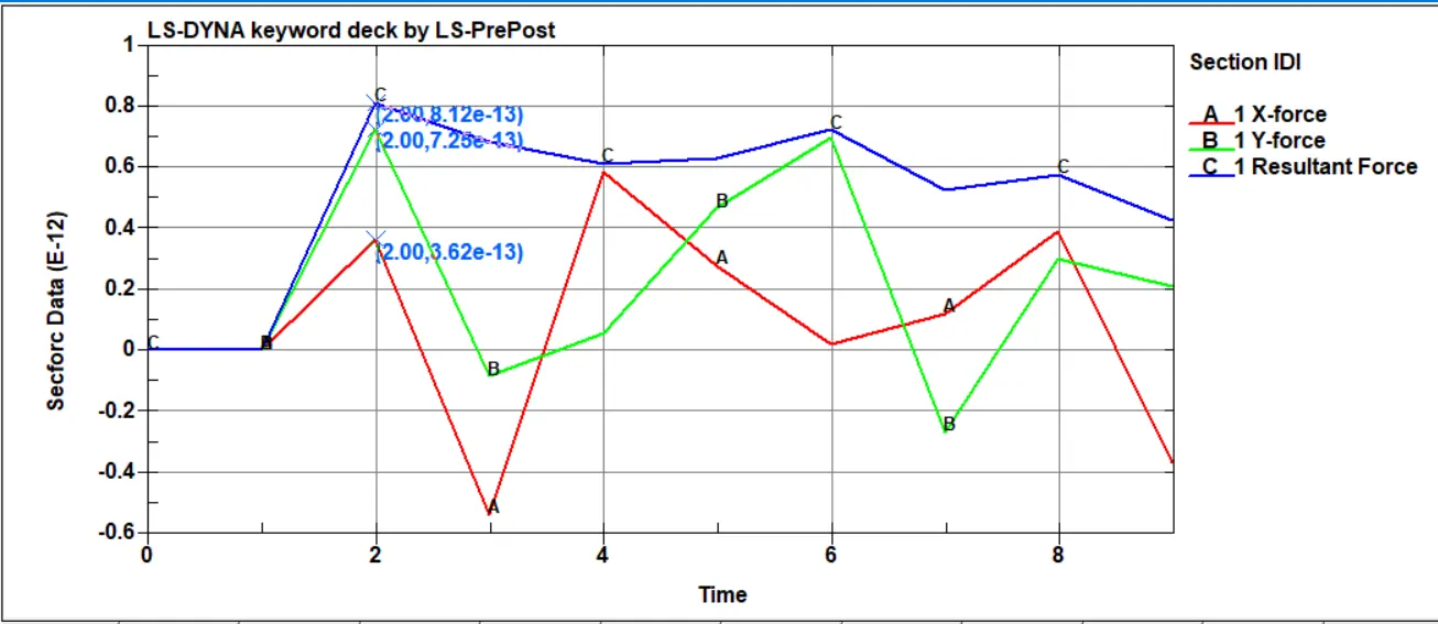
The maximum cross-sectional forces 8.12e-13N in 5ms via Resultant force, and X force and Y force occurs in the cross-sectional area.
4. Acceleration X direction of the node at midplane for beam element,
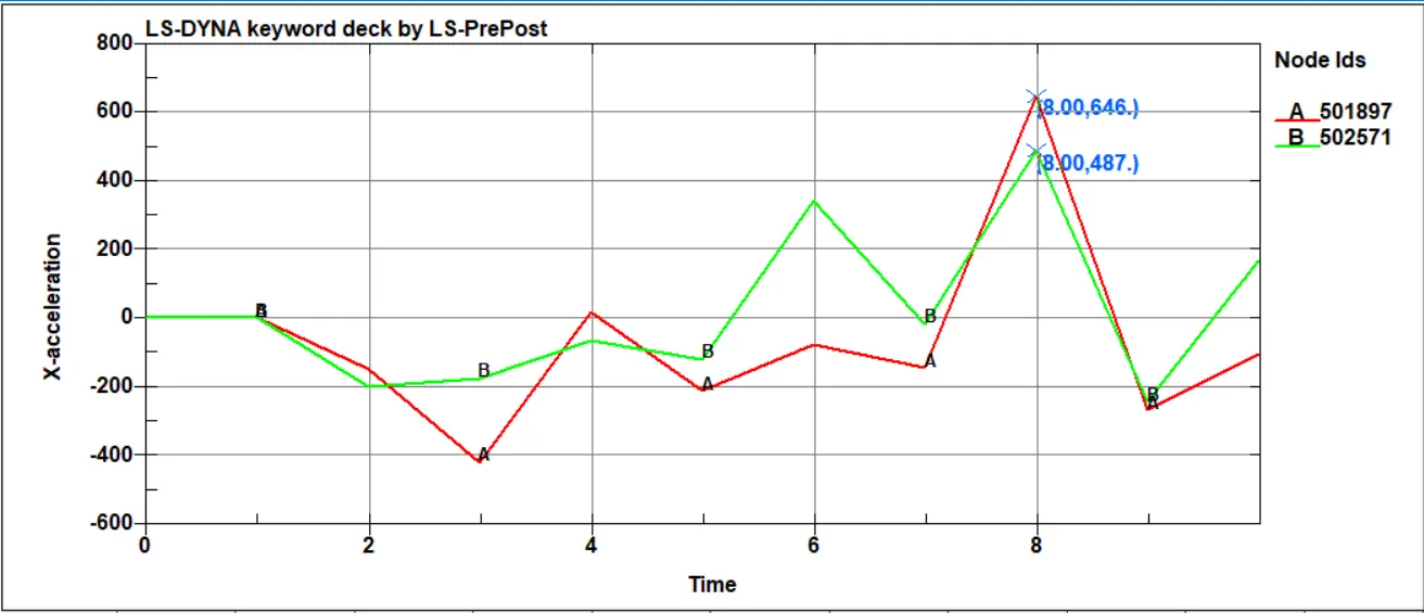
The maximum acceleration occurs in the X direction of the nodes at the midplane for beam element 646mm/ms2 at 8ms.
5. Acceleration Y direction of the node at midplane for beam element,
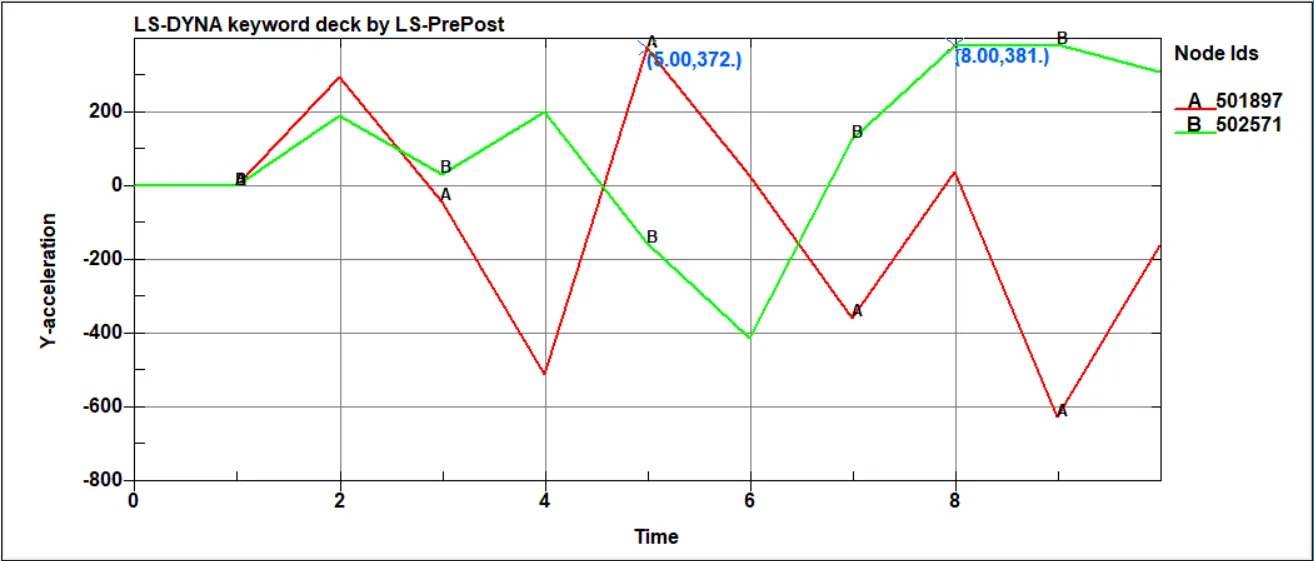
The maximum acceleration occurs in the Y direction of the nodes at the midplane for beam element 381mm/ms2 at 8ms.
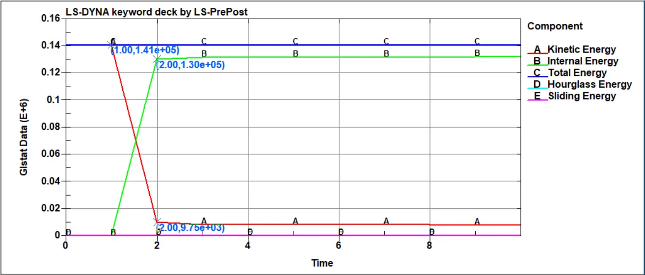
6. Energies for beam element,
7. Stress along the longitudinal axis,
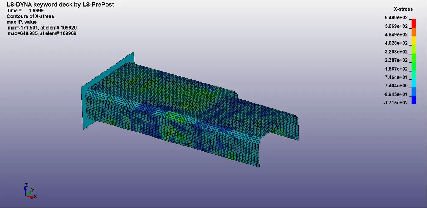
the maximum stress at the time of failure 6.490e2
8. Strain along the longitudinal axis,
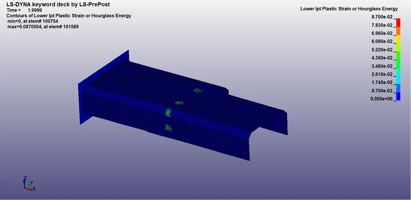
the maximum strain at the time of failure 8.7e-2
Element Failure Time,
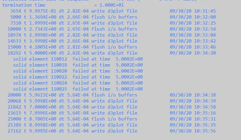
Conclusion,
Beam Element Solid Element
Axial Force 2.32e3N 994N
Shear Force 1.04e3N 2.43e3N
The beam has been given some thickness which is less when compared to its thickness. Its tensile resistance is maximum because the axial force of beam elements in more than the beam elements can also be compared to the plane stress and strain criteria. Beam and Solid elements are set steel, it's the thickness that matters. The width and thickness of the solid elements are observers to be 3mm approximately. Solid elements are more preferable are uncertain of which element to be considered. There are sliding and hourglass don't form that was no contact between the two parts through the simulation for both beam and solid elements. The failure of all the element both beam elements and the solid element at half the termination time (5ms)