AIM
To study the crash simulation of a assembly model with spotwelds and study differances in forces devoloped when the spot weld is modeled with beam elemant and with soild elements.
OBJECTIVE
We have a Assembly model with two parts with us and we need to prepare a deck for simulation in which this is crashing into a rigid wall .At first we just assign only an elastic material to the model so that we can check for the funtioning of the deck,Since in case of any error made while creating the deck will be shown once after we do the solving.So we can make sure that the problem with all other keywords are nill and so that we can then assign a non linear material to the model .In 1 st case we will be connecting the parts using the spotwelds modeled by Beam elements, while in the 2 nd case we will be modeling the spot welds using the solid elements.Then from that we need to extract the details such as follows;-
- Input .k file and output files (d3plot, glstat, sleout, rcforc)
- Animation of the final simulation
- Cross-sectional force generated in the middle of the model (along its length)
- Acceleration plot of a node in the middle of the model (along its length)
- Maximum directional stress and strain along the length of the model (X strain, Y strain etc)
- Plot of all energies (total, internal, kinetic, hourglass, sliding)
- Compare the accelerations and stress/strain plots of 1.2/1.5mm crashboxes
1) CASE SETUP
Here we first need to import the only mesh model keyword file into the LS Prepost.For that open LS Dyna > File > Open > browse for the spotweld model .k model >Open.This will open the model of the spotweld in the LS Prepost.First we need to create the material for the parts .We are creating a Linear plasticity MAT_24 material for the parts.At the same time applying a non linear material at the begining itself may throw us errors because of the complexity it creates for the problem.So in order to check whether our problem is defined correctly we are first applying an elastic material and check the deck by running it.If everything seems fine.Then we can move on to define a non linear material.Here in Ls DYna there is no unit system.Its always user wish to define the unit system as per our wish.Here we are using a unit system gm/mm/ms. since this is an impact test and it will be carried out for about 150 milliseconds because the entire impact will happen for maximum for 150 milliseconds.Normally the impact will be end in 120 milliseconds but the rebounding will also happens for the next 30 Milliseconds.
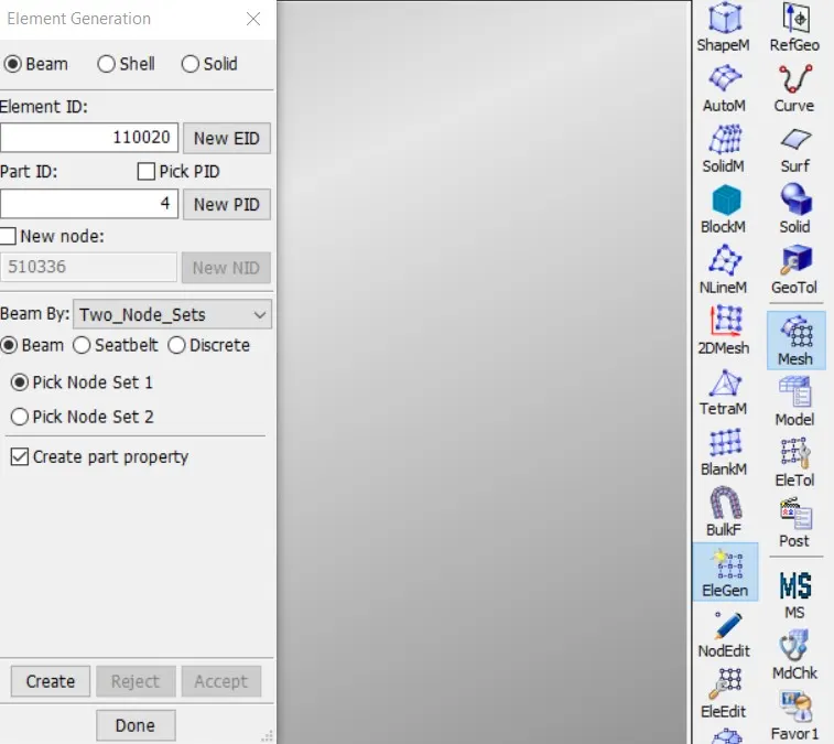
i)We need to conncet the parts using the spotwelds .As a first case we will be connecting the parts using the BEAM elements.For creating beam elements we can Go to mesh > Elemenet generation > Beam > Give Part ID > Choose the node sets in two parts with which we need to create the spot weld >Done
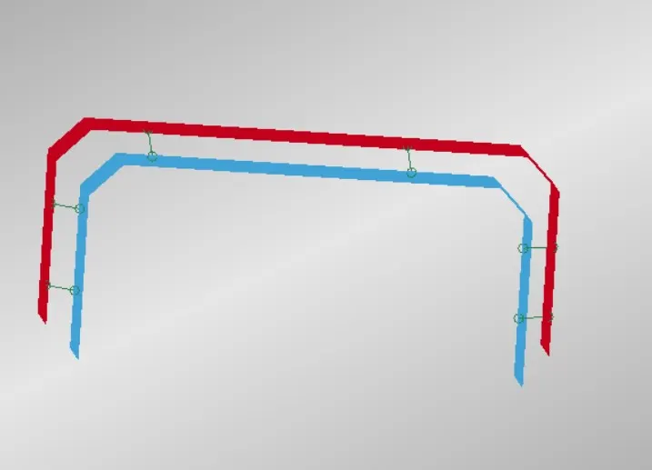
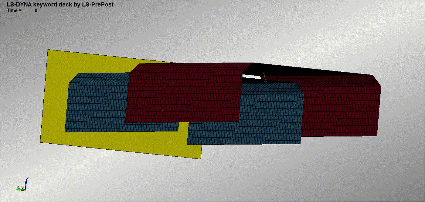
This will create the beam element in between the partts .Similarly create six beam elements symmetrically in the model.
Fig 1.1 Element Genration Window
Fig1.2 Six symmetrical Beam elements formed in between parts
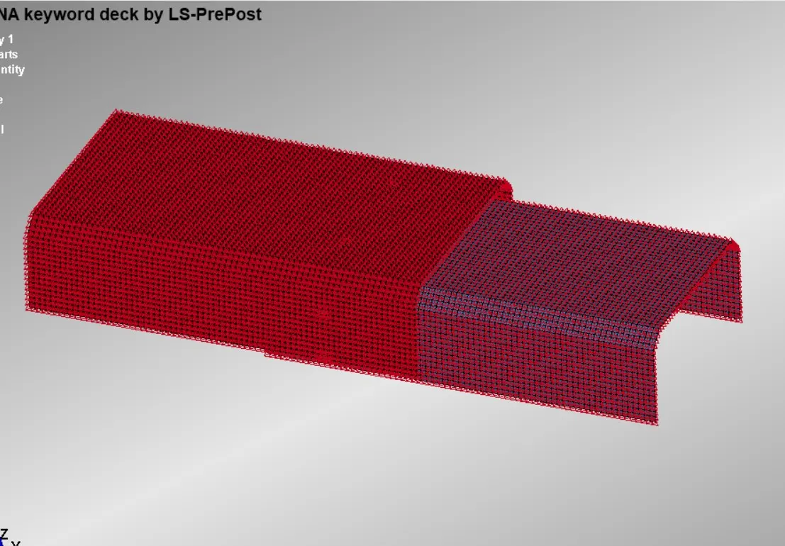
In 2 nd case we need to create solid elements between the parts .To create solid elements we can make use of Same element generation window.Here we nee to place the radioo button in solid and the sollid elements creation by shell face drag and se the thickness as the distance between the parts and give the direction in which we need to create the solid element and click create .This will show as the preview of the solid element,iof it is acceptable to us ,then accept it or otherwise reject it.Similarly six differant solid connection need to be done.These six solid elements will have differant thickneess as the distance between elements in two parts are differant in differant areas .So make use of the measure tool and measure the proper thickness and then assign thickness to solid elements.
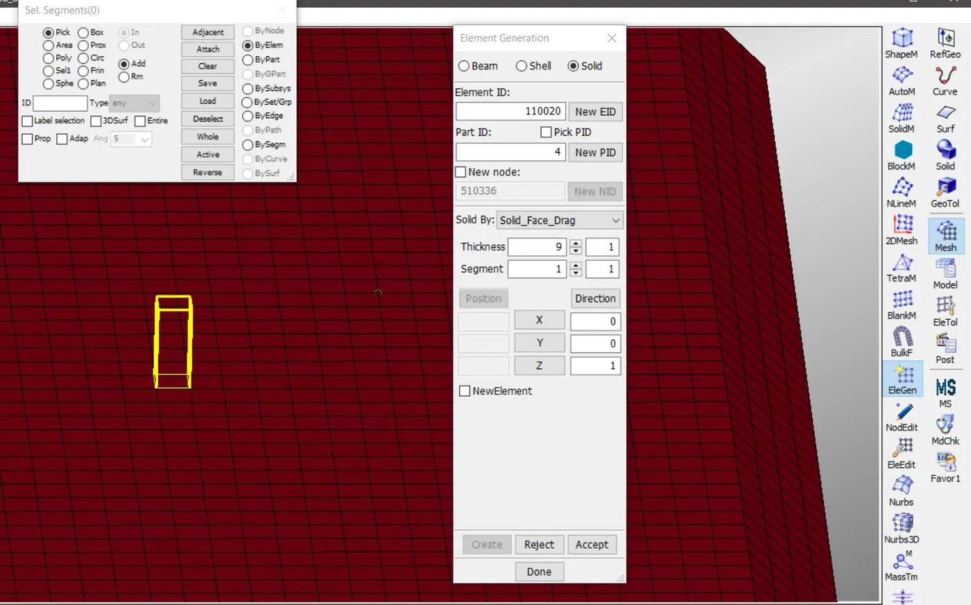
Fig 1.3 Solid elmenet creation with Element Generation Window
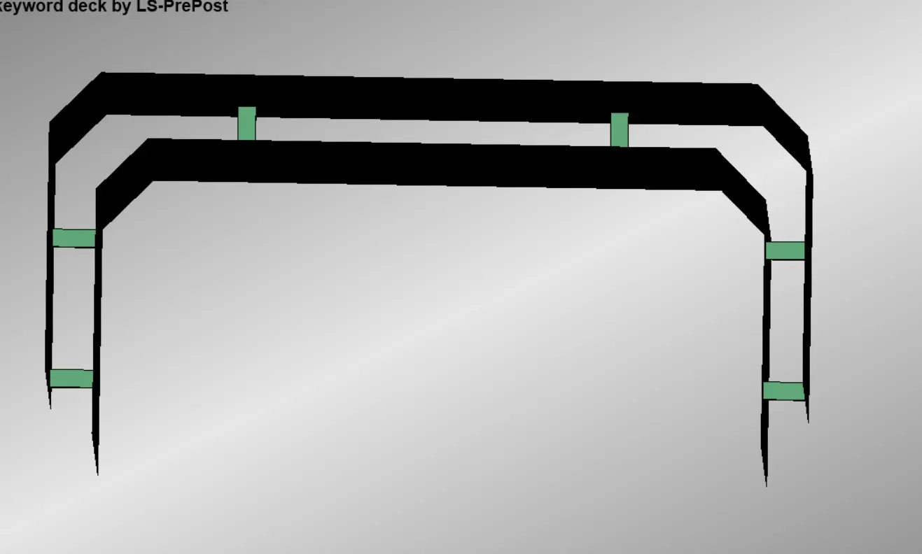
Fig 1.4 Symmetrically arranged solid elements
We create the solid elements and set evry solid elementsin same part Isd ,since w need to make contacts between them and the outer and inner plates.So contacts defined individually to the each spolid elements and the plates will leads to contact and numerical instability.So in ordr to tackle that we can assign every solid elments in one part ID and then we can assign a single contact betwen plates an solid elements.
To create the linear elastic material for plates we need to Choose Model on side tool bar area > Select KEYWORD > Choose MAT Keyword > Open the MAT_ELASTIC keyword CARD >Select the plates part iD .>Input the values of Rho,E, and Poisson's Ratio in that Card >Accept > Done.Similarly select MAT_Spotweld to create a spotweld material in the deck.
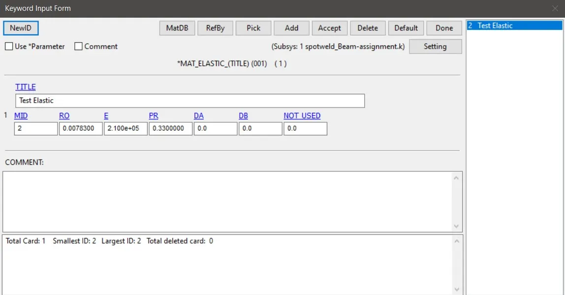
FIg 1.5 elastic material Card
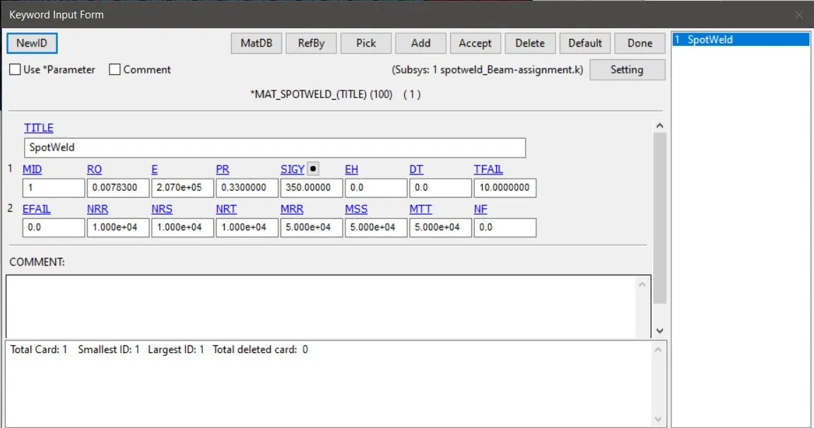
Fig 1.6 Mat_Spotweld Card
SECTION CREATION
Here we will be creating a shell section card and a solid section card.Here we already used the Mat_Spotweld material card.So when we are using it we should go with ELFORM is 1 for solid elements and ELFORM is 9 for beam elements.We can use the ELFORM for shell elements as 16 which gives us the fully integrated elements and we will be asssigning 1.2 mm thickness to the shell elements.
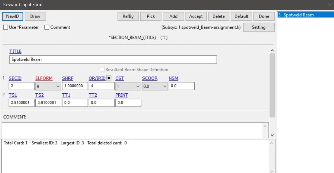
Fig 1.9 Section_Beam Card
Since the mesh length is 3.5 mm in the mesh.We should have the beam area and solid spotweld base area must be same.
π d^2 /4 = 3.5 x 3.52
ie, d =3.91 mm
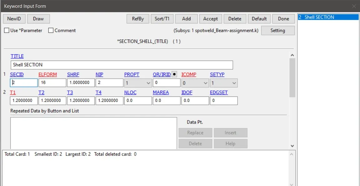
Fig 1.10 Section_Shell Card
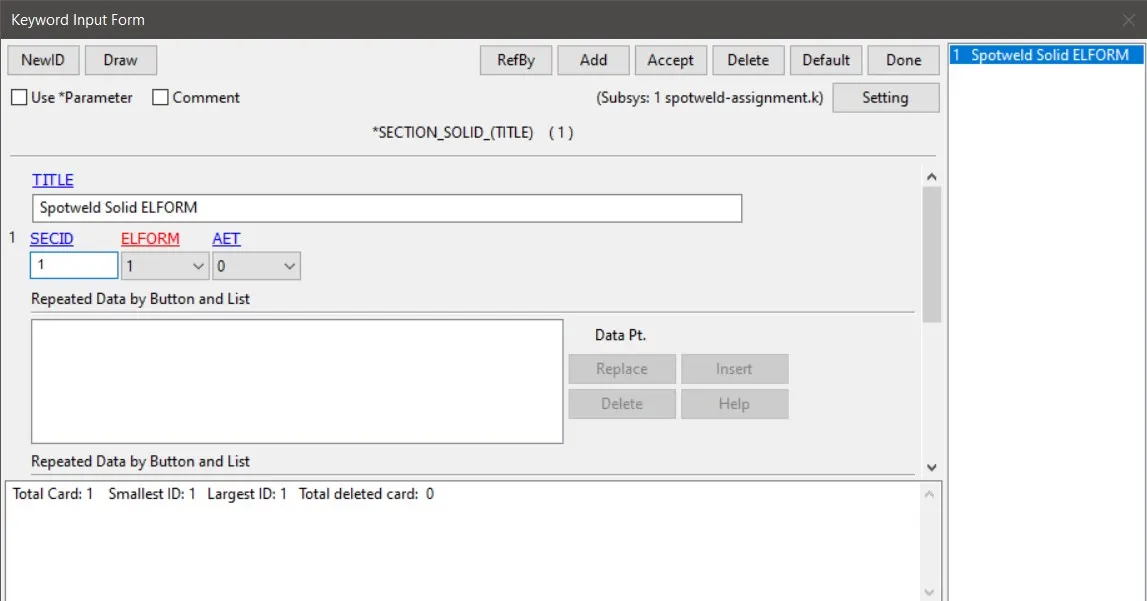
Fig 1.11 Section_ Shell Card
Creation of Rigid Wall
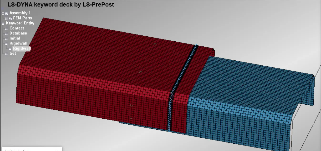
In the simulation we need to crash the model witha rigid wall.For that to make happen we need to first create a Rigidwall in the model.This can be done by Model > Create Entity >Select the Rigid Wall > Place the radio button in planar > Select the option N1 - N2 > then seleect the choose two nodes in such a way that the order in which the nodes are choosen will be the same direction in which we want our rigid wall normal to be ( Choose the normal of the rigidwall should be in opposite direction to which the model is travelling) > Accept > Done
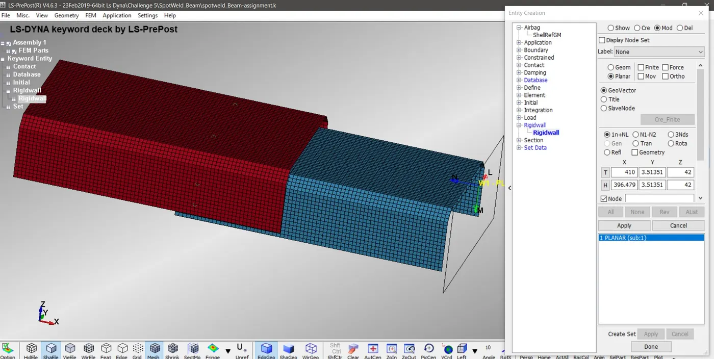
Fig 1.12 Rigid Wall Creation
Applying Boundary condition
As a boundary condition we are applying a speed of 50kmph which is equals to 13.88 mm/ms .To apply this,we need to apply this to entire node in model.So we need to create a node set data.For this go to create entity > Set data >Set Node data > select the entire noes inmodel > Apply> Done.This will create the modelnode set with the ID we specified.Then we need to create Velocity card by Model > Keyword > Intial > Velocity > Since the cordinate axis in which we need the model to move is in x- Axis give 13.88 value in Vx box > Select NSID as the Id of the node set we just created > accept > done.
Fig 1.13 Created Node set
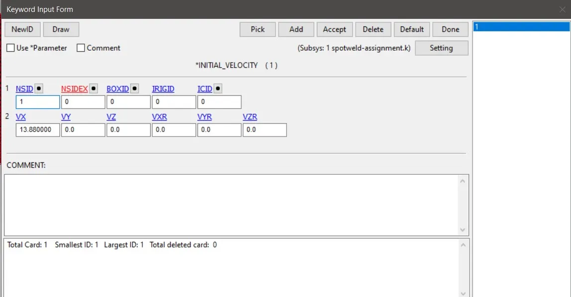
Fig 1.14 Velocity Card
CONTACT CREATION
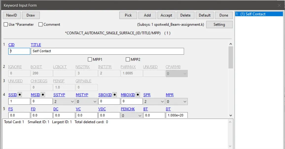
Since we are impacting the model with a rigid wall there is no need to make a new contact as the rigid wall is in built have the contact condition .We need to specify only the Node Set ID of the model in the NSID column in Rigid Wall Card.But As there is the possibility of the model to buckles after the impact and it will came into self contact.As in real scenario we can see that the sheet metal after buckling will not penetrate into other .So inorder to get the simulation like that of the real case we need to create a self contact in the deck.This can be done by Model > keyword >Contact >Automatic Surface to Surface > Set SSTYP as 3 > Assign the slave as a part set of the model >Accept > Done.
Fig 1.15 Contact_Surface_to_Surface Card For Self Contact
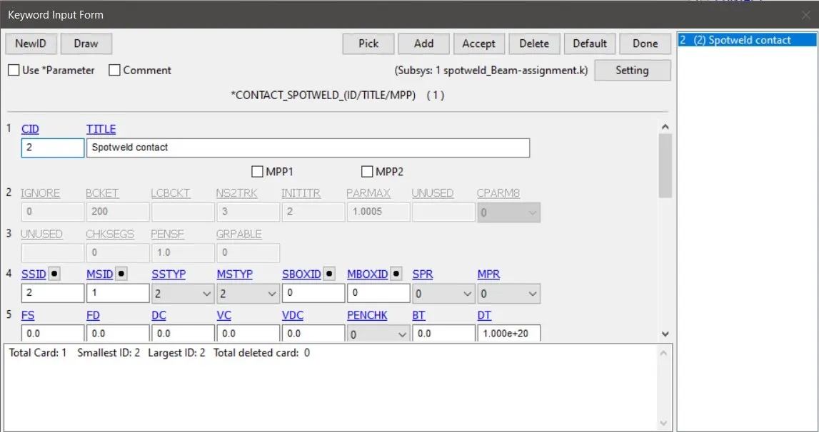
Fig 1.16 Contact_Surface_to_Surface Card For Spotweld
CONTROL CARD CREATION
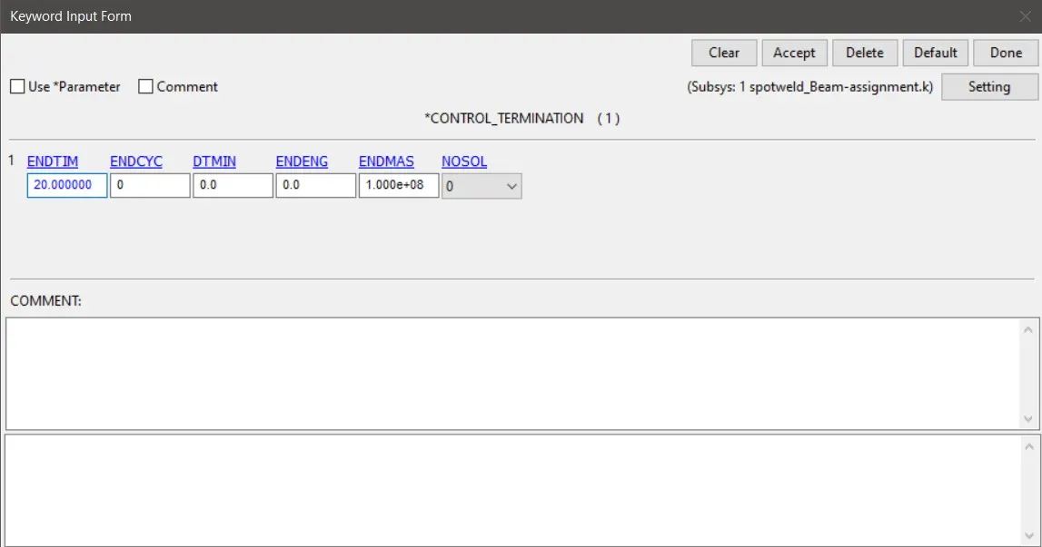
We need to specify for how long our simulation would run.This can be incorporated using the control termination Card.For this Model > Keyword > Place the radioo button in ALL > Control >Termination > Specify the End Time as 20 mm > Accept > Done
Fig 1.17 Control Termination
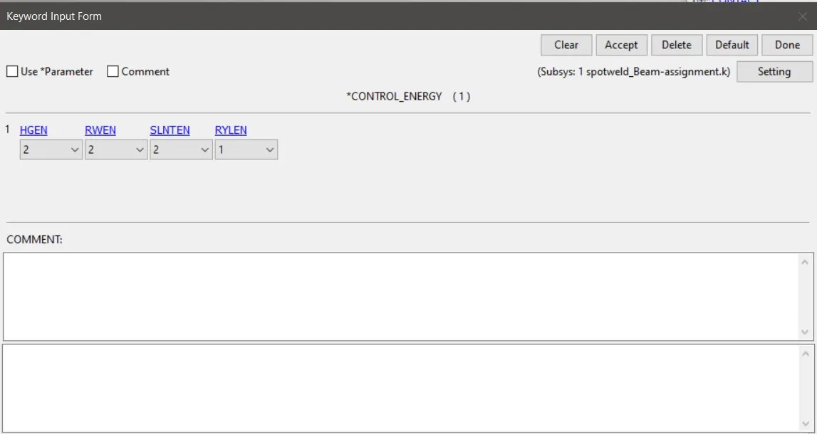
Since we need to request for hour glass energy and sliding energy we need to create a control energy card also .This can be formed by Model > Keyword > Place the radioo button in ALL > Control > Energy > Set HGEN and SLNTEN as 2 > Accept > Done.
Fig 1.17 Control Energy
Then we need to create a section in the model mesh as we are asked to find out the sectional force through the length of the model .So inorder to make a section, First we create a node set running in a line in the middle across the model and also a element set as the referance for the node set.This will basically create the section.
Fig 1.18 Section created
DATABASE CREATION
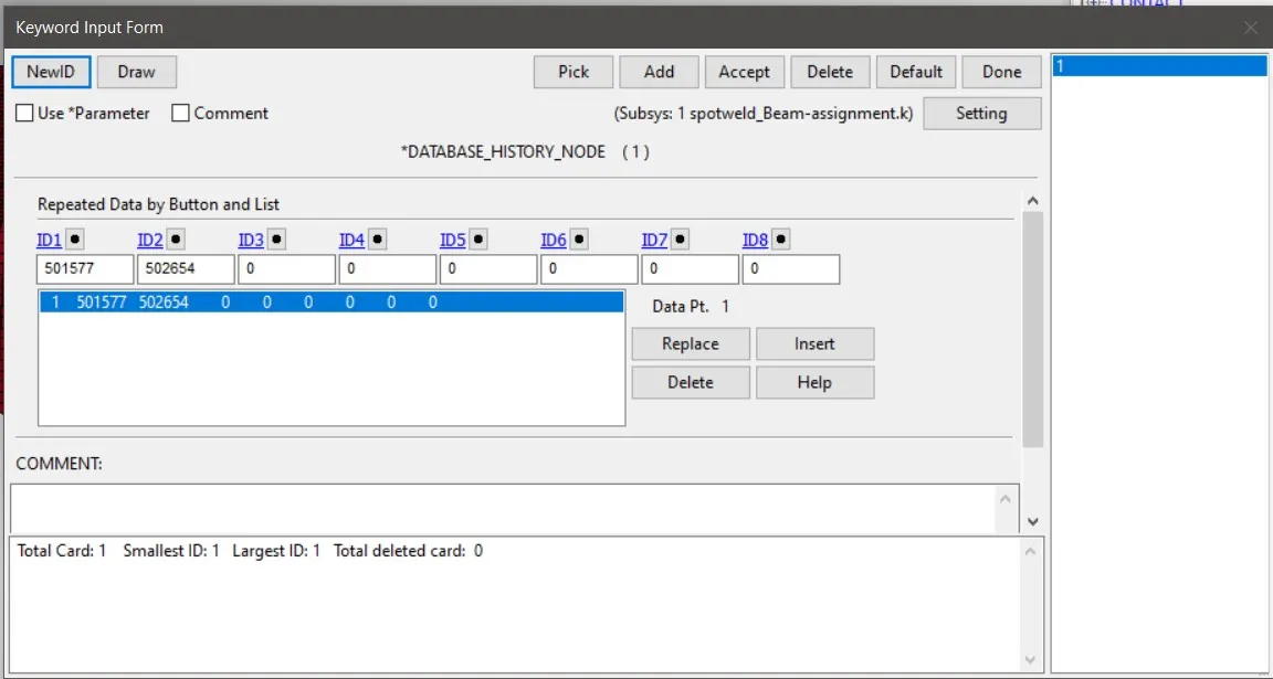
This is the card space where we need to specify what are our variables required.So in ascii option card we need to set in GLSTAT,MATSUM,SLEOUT,RCFORCE,RW FORCE,SECFORC which gave us the energy values,part energies,sliding energy,rigidwall contact force,and section force respectively.And set the dt which is the time for recording the plot values as 0.1 mm.Here we also gives NODE_out in ascii option card as we need to get the node acceleration values.But even we asked for the secforce and node out ,we need to define the area where we need to store these values .For defining the section we need to create CROSS SECTION_SET in database keyword .Then assign NSID and SSID in it.Similarly for defining the NODE in whiich we want the output time history,we create a HISTORY _NODE card in database keyword .Then we specify the node in which we need to get the output .Similarly to define the strain in the D3PLOT itslef we need to specify EXTENT_BINARY Card in the database keyword and set STRFLAG as 1 .So that the strain will be recorded.
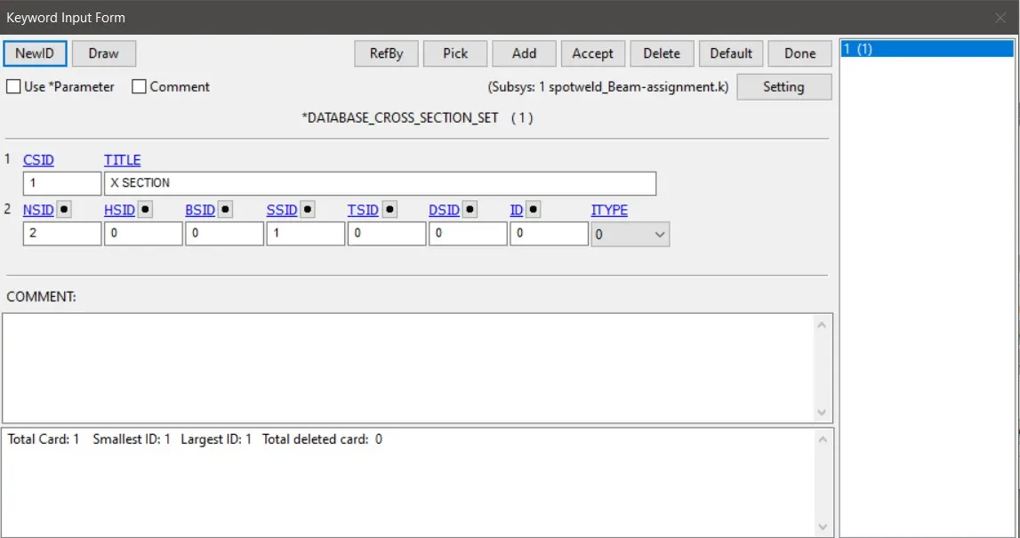
Fig 1.19 Database_Cross_Set Card
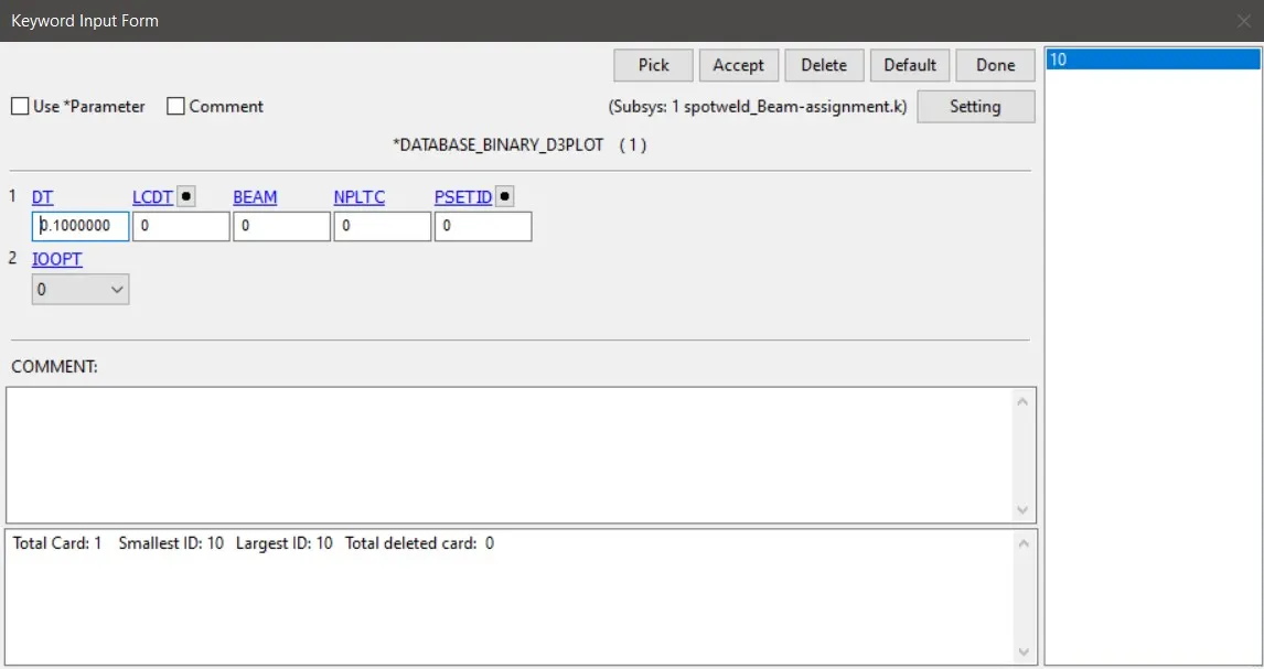
Fig 1.20 Database_Binary_d3Plot Card
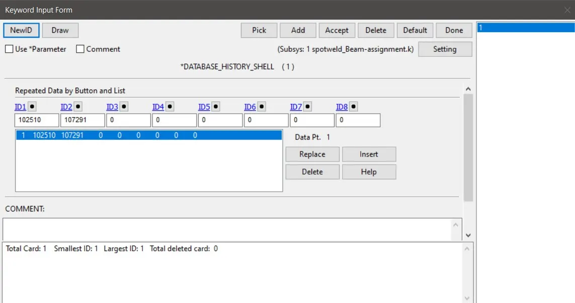
To store the stress and strain value at the middle in differant axis ,we can ask for the element history.Here in LS dyna we can use ELOUT in ascii option to request for element output.This can be stores by using the BINARY >HISTORY SHELL >Specify the ID of elementwe need to take the history (here we take Shell element with ID1191)> Accept >Done.Then in the Model >keyword >Binary >binary D3THDT >Give dt as 0.1 ms >Accept >Done
Fig 1.21 Database_History_Node
Fig 1.22 Database_History_Shell
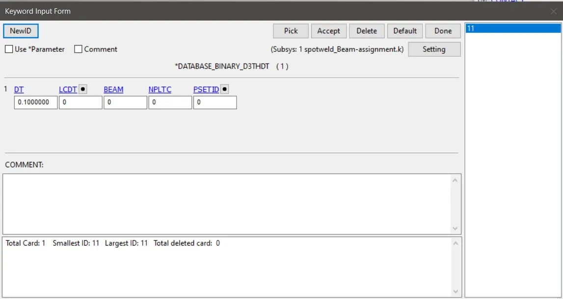
Fig 1.23 Database_Binary_D3THDT
POSTPROCESSESING
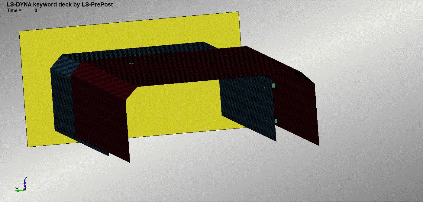
Fig 2.1 Simulation of crashing of model with beam spotweld on rigidwall Fig 2.2 Simulation of crashing of model with solid spotweld on rigidwall
We can see the BEAM element gets deleted from the model exactly at the 10 th millisecond which is the halfway time of the simulation.
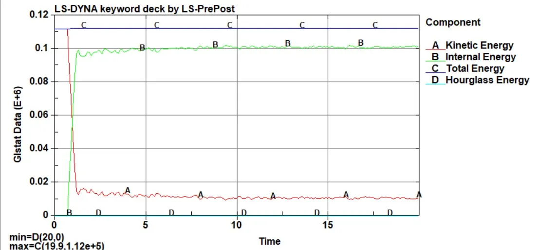
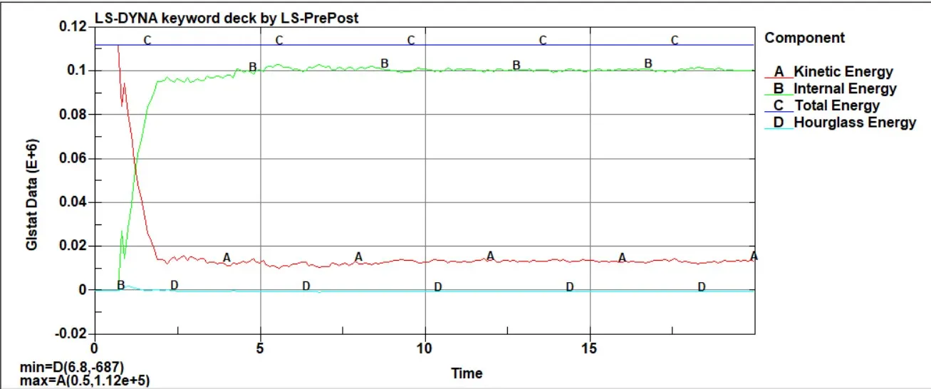
Fig 2.3 Glstst Enrgy Curve of model having spotweld with beam element Fig 2.4 Glstat Enrgy Curve of model having spotweld with Solid element
The above figures are making sense ,as soon as the model makes its contact with the Rigidwall , the kinetic energy is reducing to a large extent and the internal energy is rising high as the kinetic energy is converted into the internal energy. As obeyed by the Energy conservation law ,the total energy remains constant.Since we have used the fully integrated shell elements the hourglass energy is zero.The kinetic energy imparted due to the velocity of model on rigid wall got transffered to internal energy to some extent and some amount of enrgy left with the model as KE which is used for the rebounding to happen.
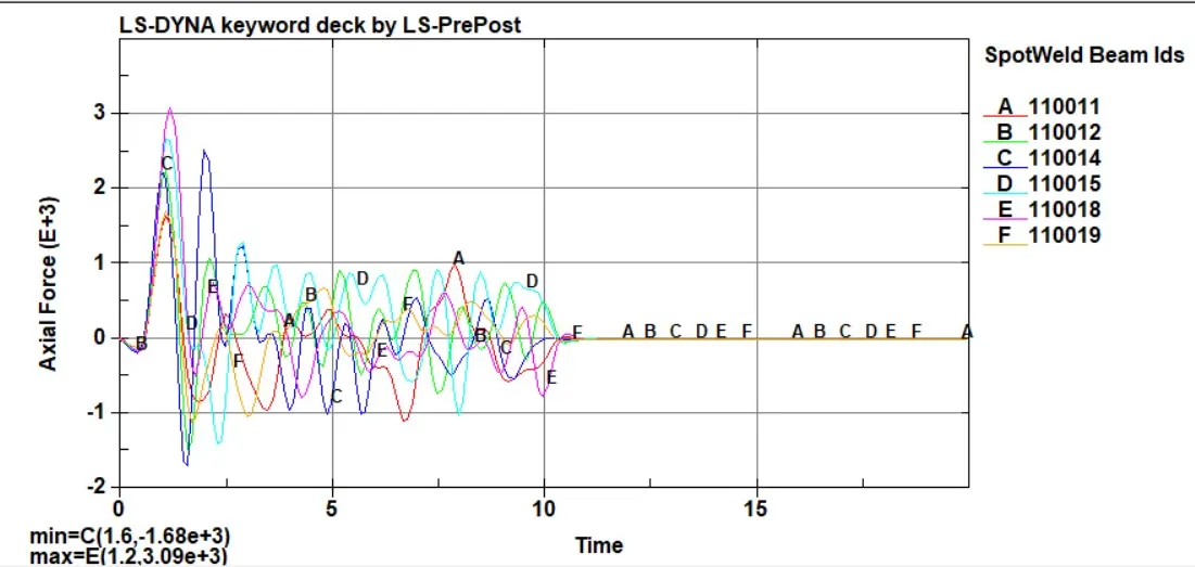
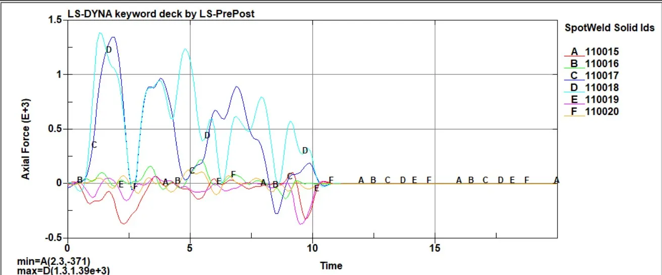
Fig 2.3 Axial force generated in each spotweld with beam element Fig 2.4 Axial force generated in each spotweld with solid element
After the 10 th ms at which the spotweld breaks ,the axial force on both the spotweld cases comes to zero force in axial direction as we expected.Axial force is more in Beam element Spotweld than the solid element spotweld. Even if the force imparted by the rigid wall due to impact is same ,the axial force generated on the solid elements are more than in beam element.Maximum force in axial direction comes in both cases in nearly in same time itself, 1.2 -1.3 ms .
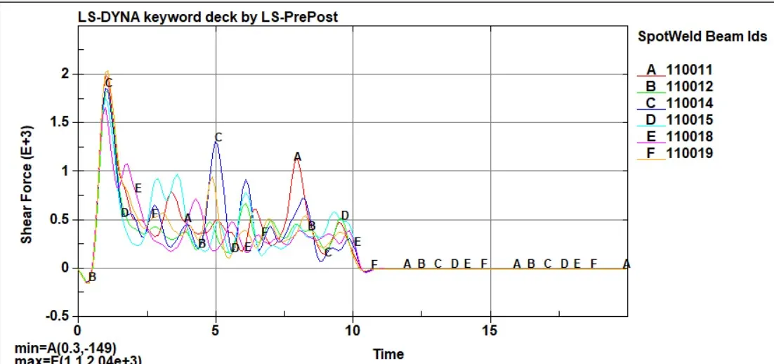
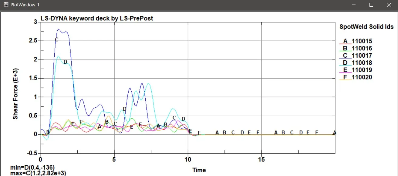 Fig 2.5 shear force generated in each spotweld with beam element Fig 2.6 shear force generated in each spotweld with solid element
In shear force case,Solid element spotweld is transferring more force than the beam element spotweld.So this much amount of maximum force should be generated to break that solid spotweld.Here also the maximum shear force happens in both cases in exactlly same time,ie , at 1.2 ms. The solid elements at the top of the plates are having more shear force acted on it.So those are the spot welds which were hard to remove.
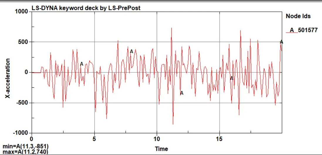
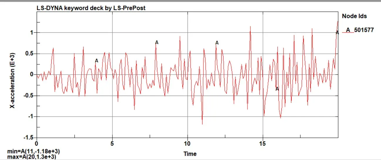
Fig 2.7 Accleration of Node in X direction in beam spotweld Fig 2.8 Accleration of Node in X direction in solid spotweld
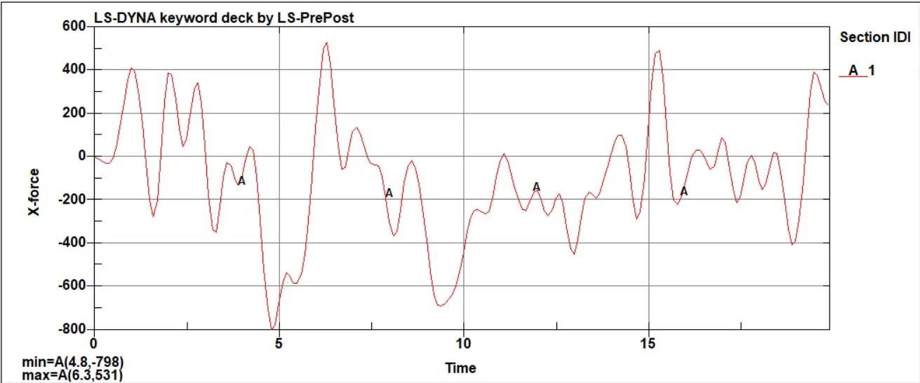
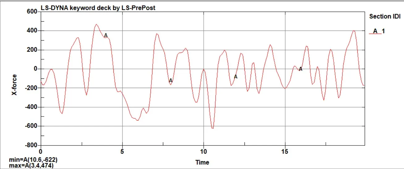
Fig 2.9 Section Force in X direction in beam spotweld Fig 2.9 Section Force in X direction in solid spotweld
Beam spotweld is showing the more amount of force through the section we created.This implies the amount of force required to break the beam spotweld is less compared to the solid spotweld.So the more amount of force will reamain after the force breaks the weld in case of beam element.That is why the force is more here.Since the force is more in beam element spotweld the acceleration of node in the part is also more in case of beam element spotweld than the one with solid element spotweld.
Conclusion
The results we obtained are trustable since the element formation is highly fully integrated shell elements ,So the hourglass energy is not visisble.So there will not be any excitation of hourglass energy.If we are not used the fully integrated elements in the part,then the loads cannot be transffered properly.To arrive at a proper conclusion about whether the beam spotweld or solid spotweld is better ,we need to get the real test data of the spotweld at which axial force and the shearforce did the spotweld breaks and at the maximum shear and axial force monitored in that spotweld in real test data.Then only we can find out which one is best for our application.But in automobile industries the usual practice is to go with the solid spotwelds.