Week - 5 - Modelling Spotwelds
OBJECTIVE: -
To simulate a crash test for sheet metal by modeling spot weld using Beam and solid (Hexa) elements using LS-Dyna.
PROCEDURE: -
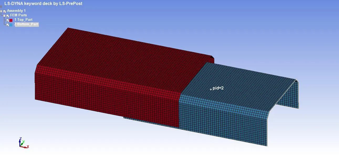
Open the LS-Prepost software, and then to import the required file i.e. spot weld – assignment.
Import the .K file format model in LS-Prepost, File – Import – LS-DYNA Keyword file – select file – Import.
Check the keyword contained in the file by Model & part – Keyword Manager – Check:Model.
TO CREATE THE BEAM ELEMENT FOR SPOT WELD
After importing the model, create the spot weld in-between the plates.
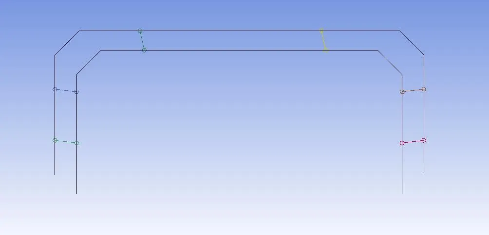
To create spot weld using beam elements, go to elements mesh - element editing - create - element type - select beam - pick P1 & P2 - give PID and create beam weld.
Once a beam weld is created, create spot welds along with the line and provide a different PID for each beam element.
TO CREATE THE MATERIAL CARD & SECTION CARD FOR SPOT WELD & PLATES
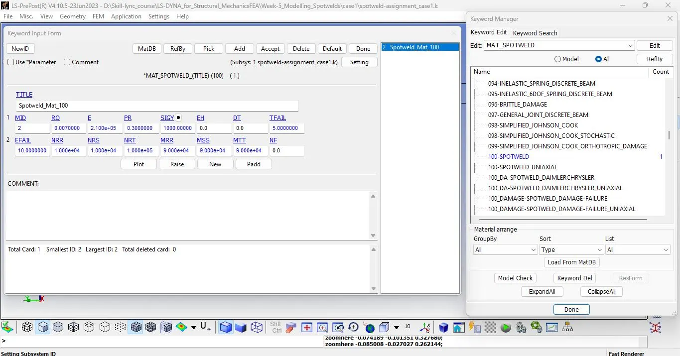
To define the material card for spot weld select MAT100 to give the steel properties. (gm,ms,mm)
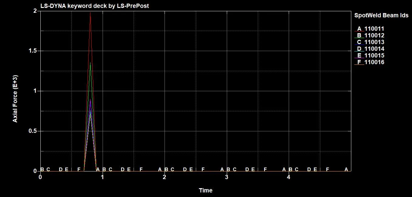
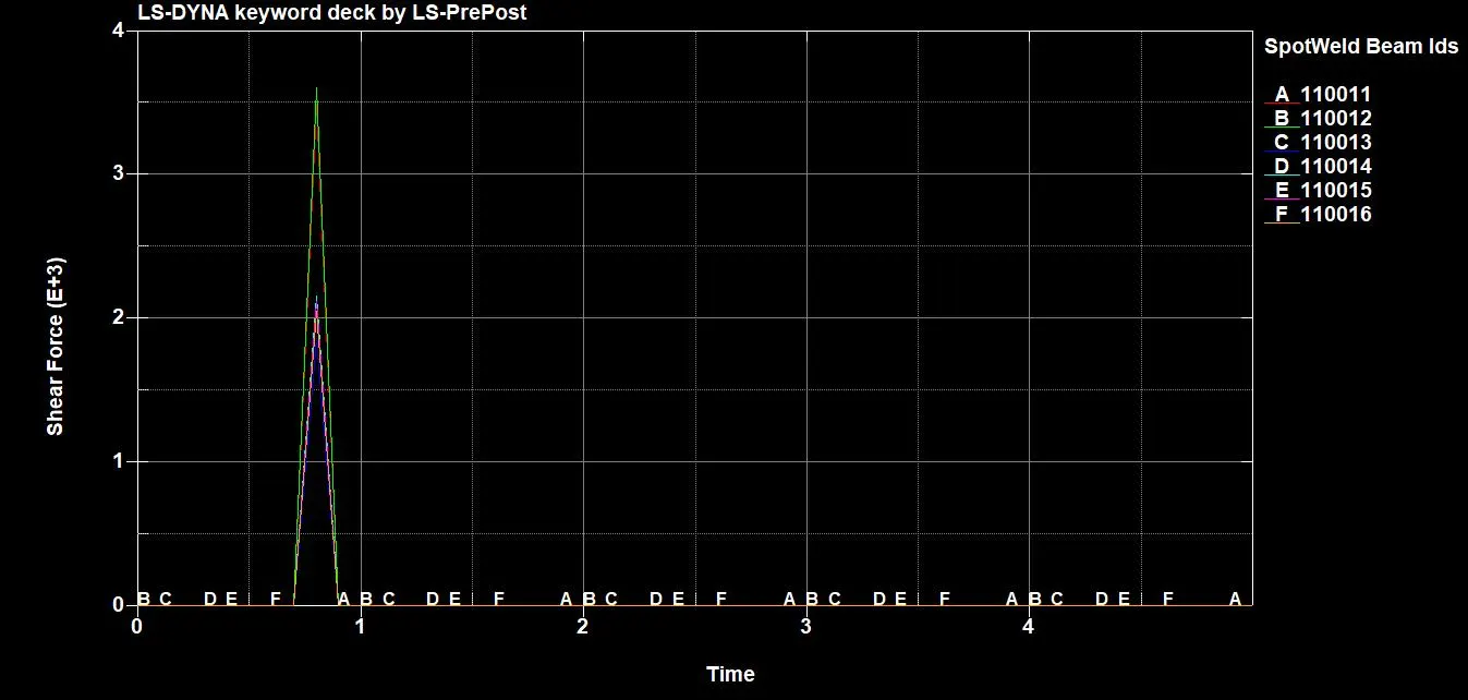
The best simulation should have a failure at half of the termination time. So put TFAIL time half of the end time in control time.
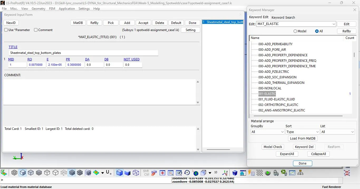
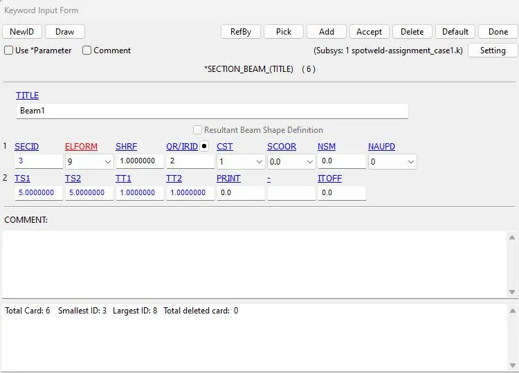
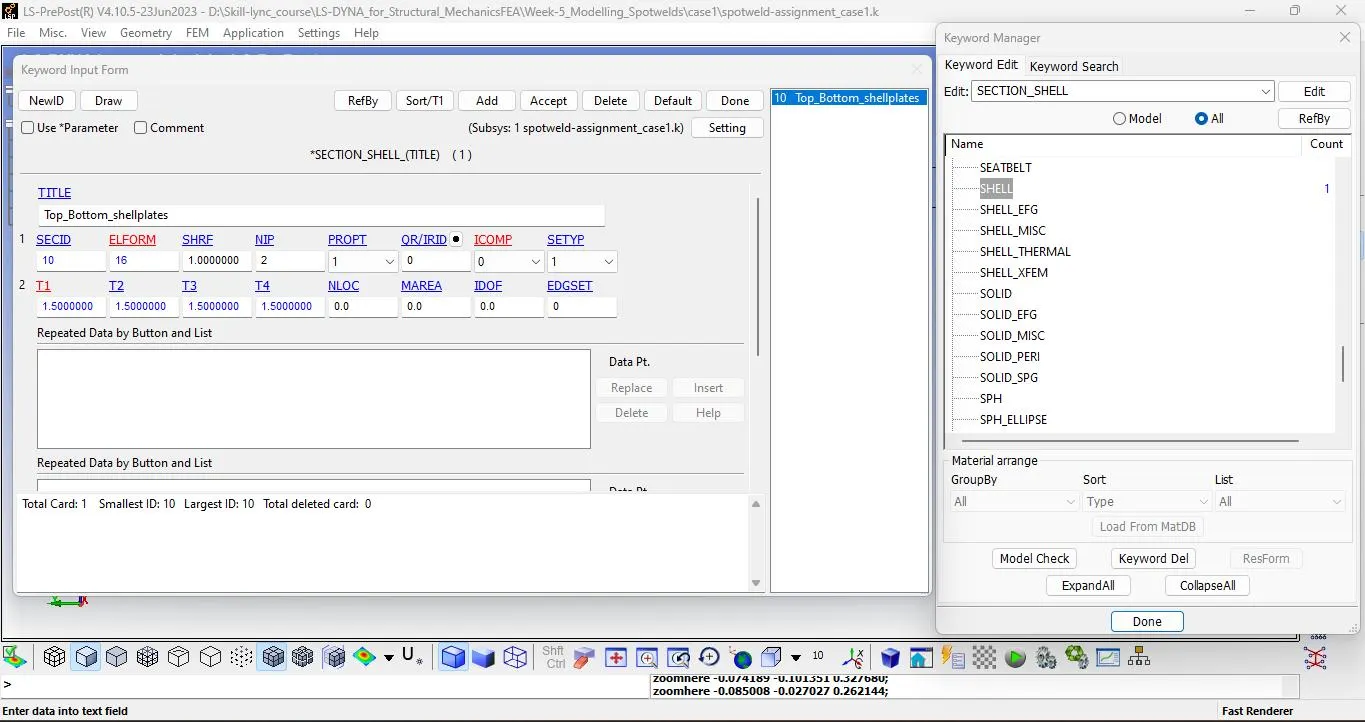
ASSIGN THE SECTION & MATERIAL CARD BEAM AND TOP & BOTTOM PLATES
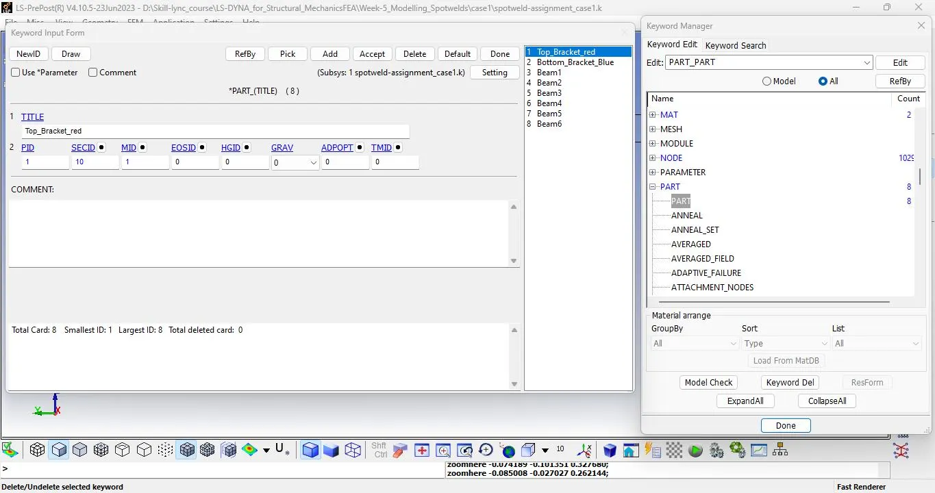
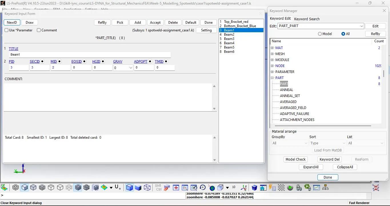
DEFINE THE CONTROL CARD FOR SPOT WELD AND FOR PLATE SELF IMPACT
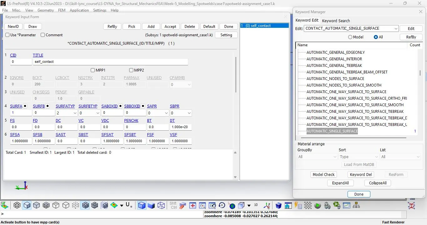
Set the plates under part-set and assign them as slaves by selecting SSTYP as 2 & MSTYP as 0 for self-contact.
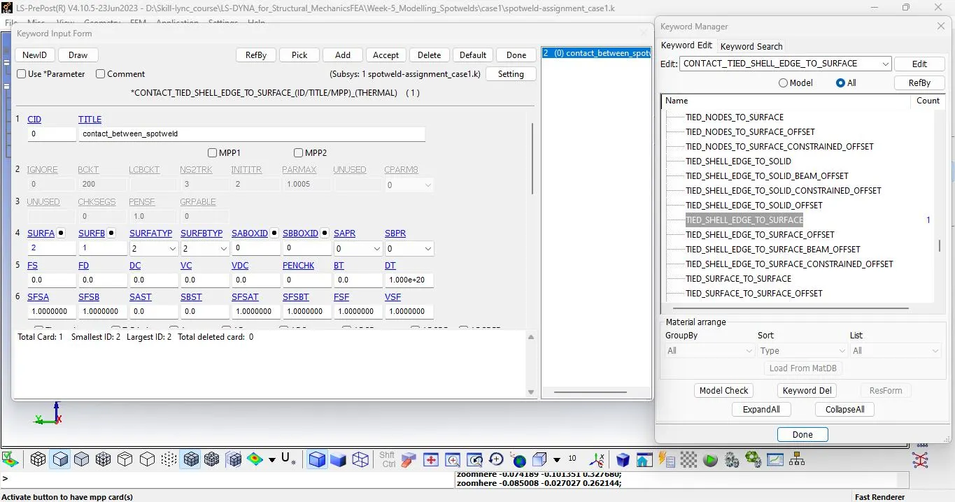
For CONTACT_TIED_SHELL_EDGE_TO_SURFACE -> Set the part-set for the beams and assign them as slave and master as plates using SSTYP as 2 and MSTYP as 2.
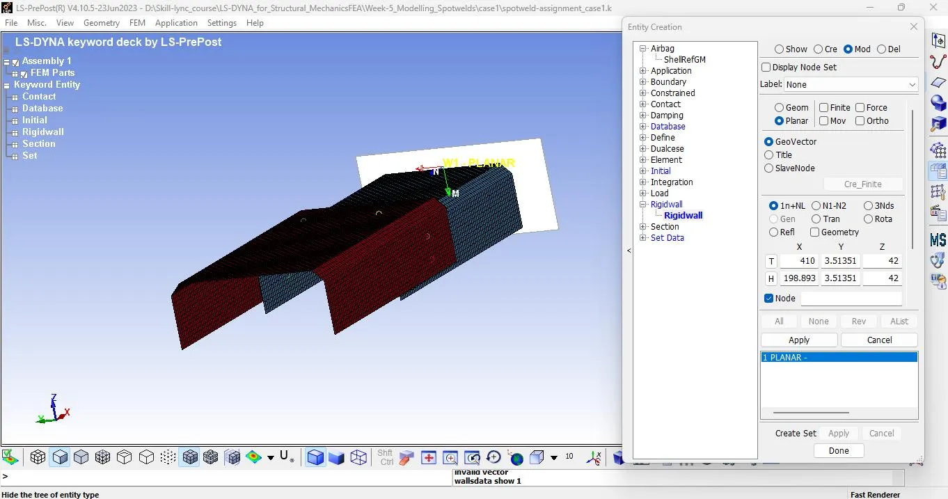
TO CREATE THE RIGID WALL 10MM AWAY
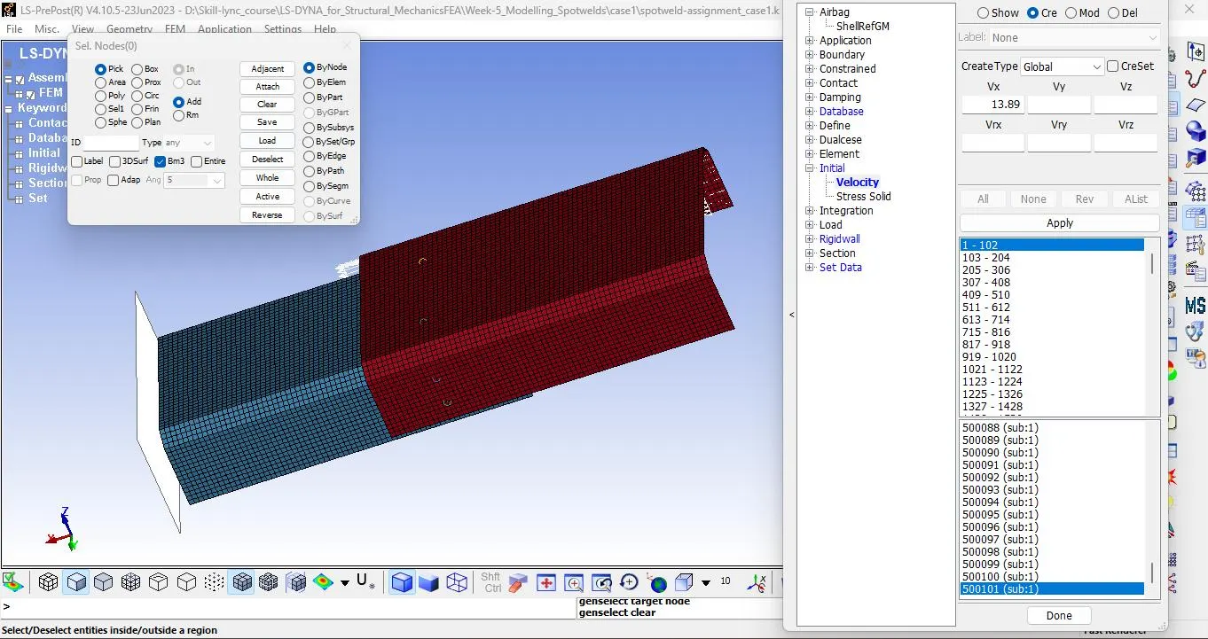
TO CREATE THE INITIAL VELOCITY FOR THE PART AS 50Kmph or 13.89mm/ms
DEFINE THE DATABASE CARDS
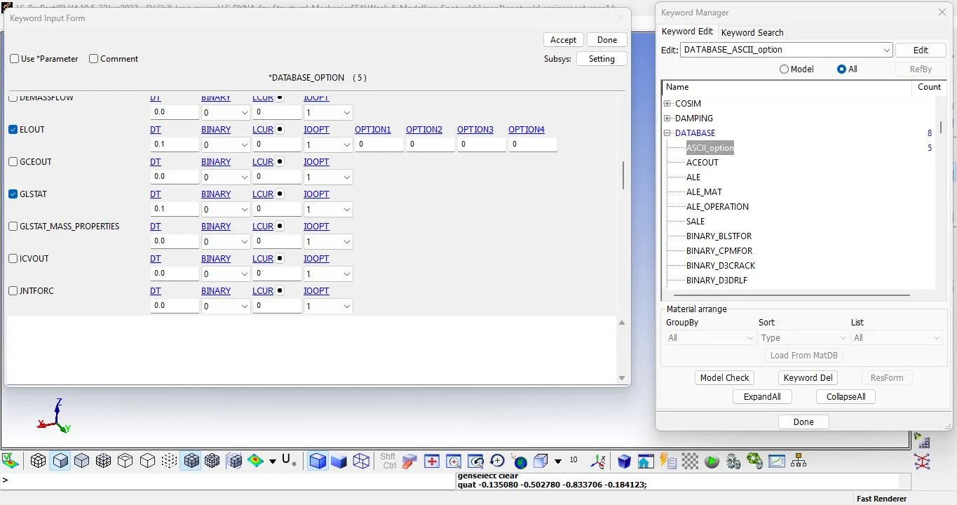
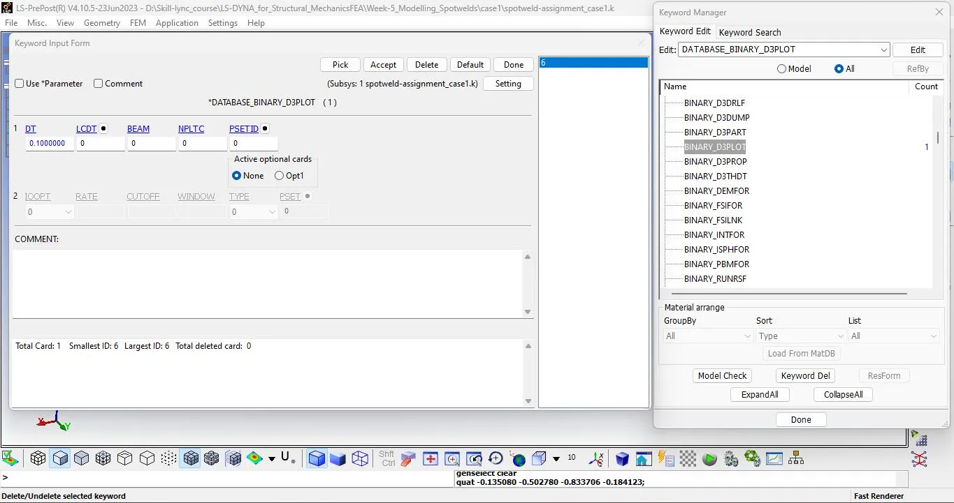
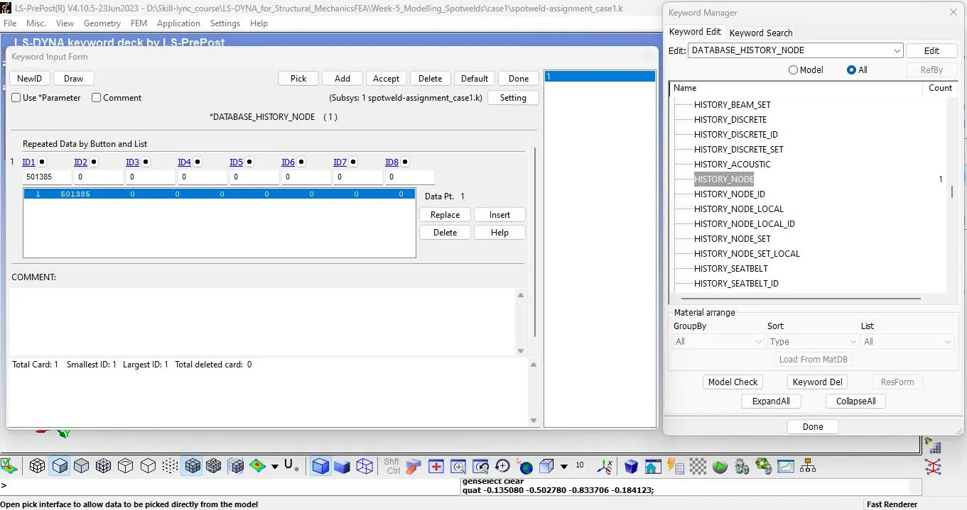
Define all the cards necessary for viewing the result during post-processing such as BINARY_D3PLOT, ASCII_OPTION, and HISTORY_NODE.
Check the ELOUT, GLSAT, MATSUM, SWFORC, and NODEOUT with DT value as '0.1'.
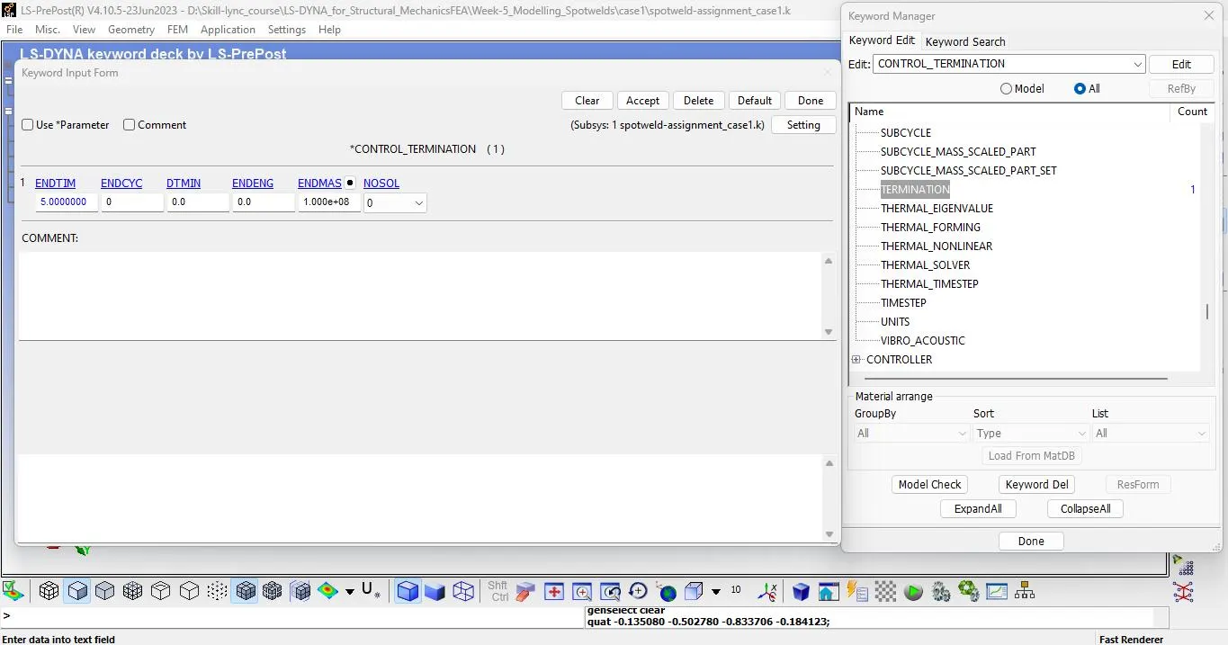
DEFINE CONTROL CARD TERMINATION
CASE 2 FOR HEXA SOLID SPOT WELD ELEMENT
Solid hexa spot weld element creates the element using the element editing option and select 8 node points.
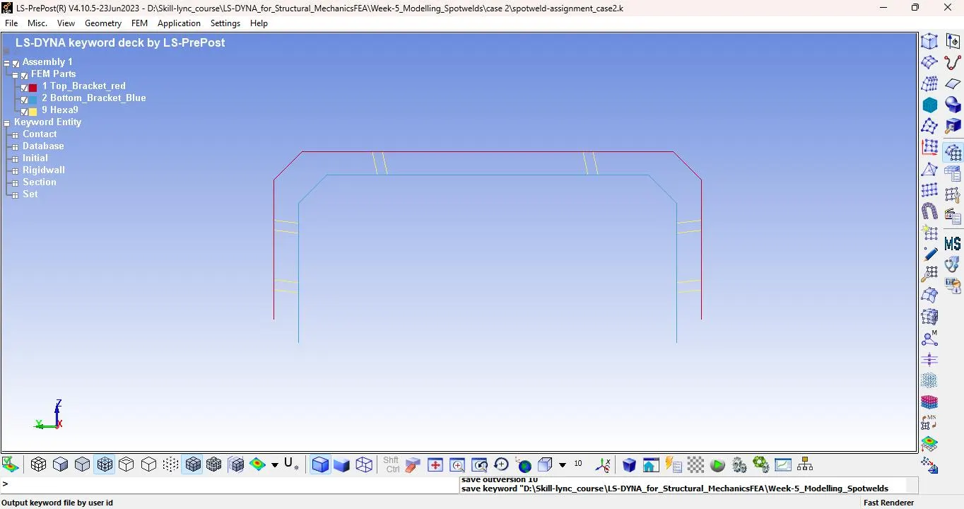
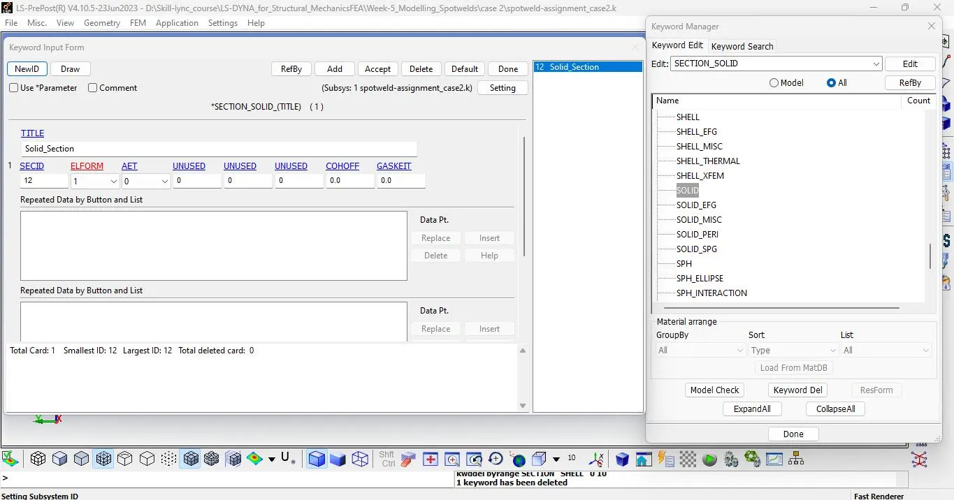
Use the Material card same as for steel created for beam elements but change the Section card as SECTION_SOILD and ELFORM 1.
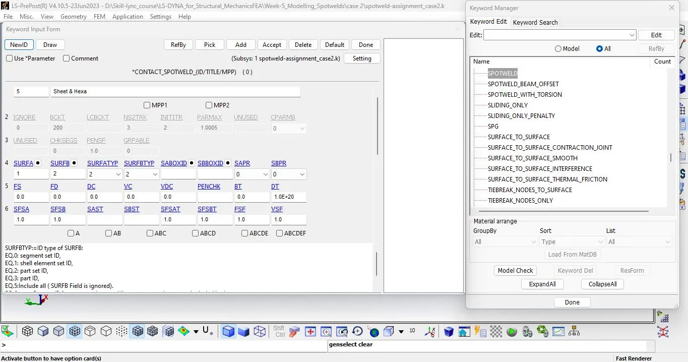
Define the contact type for Spot weld in solid element as CONTACT_SPOTWELD create as a set of parts and define Spot weld as slave and plate as master.
POST PROCESSING RESULT:-
BEAM ELEMENT CASE : 01
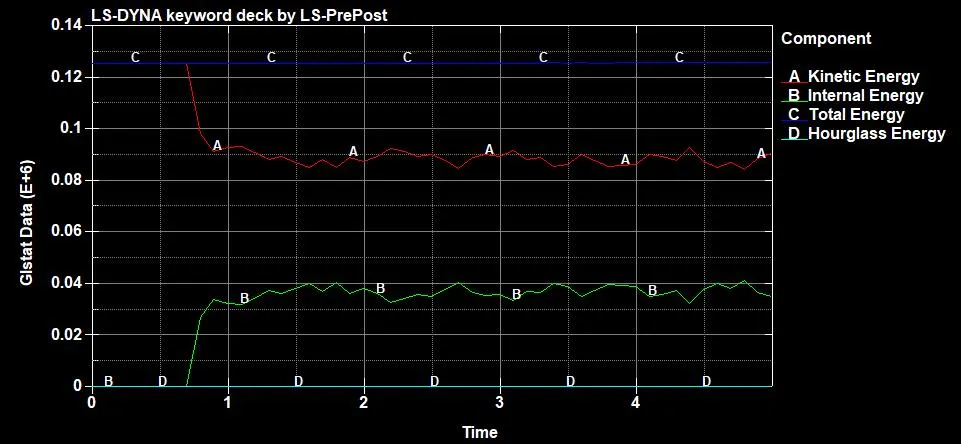
ENERGY PLOT:-
AXIAL FORCES:-
SHEAR FORCES:-
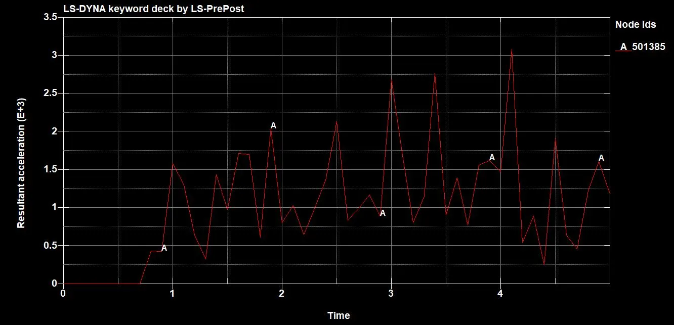
RESULTANT ACCELERATION:-
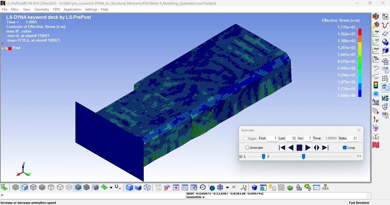
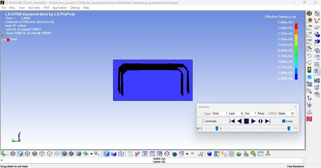
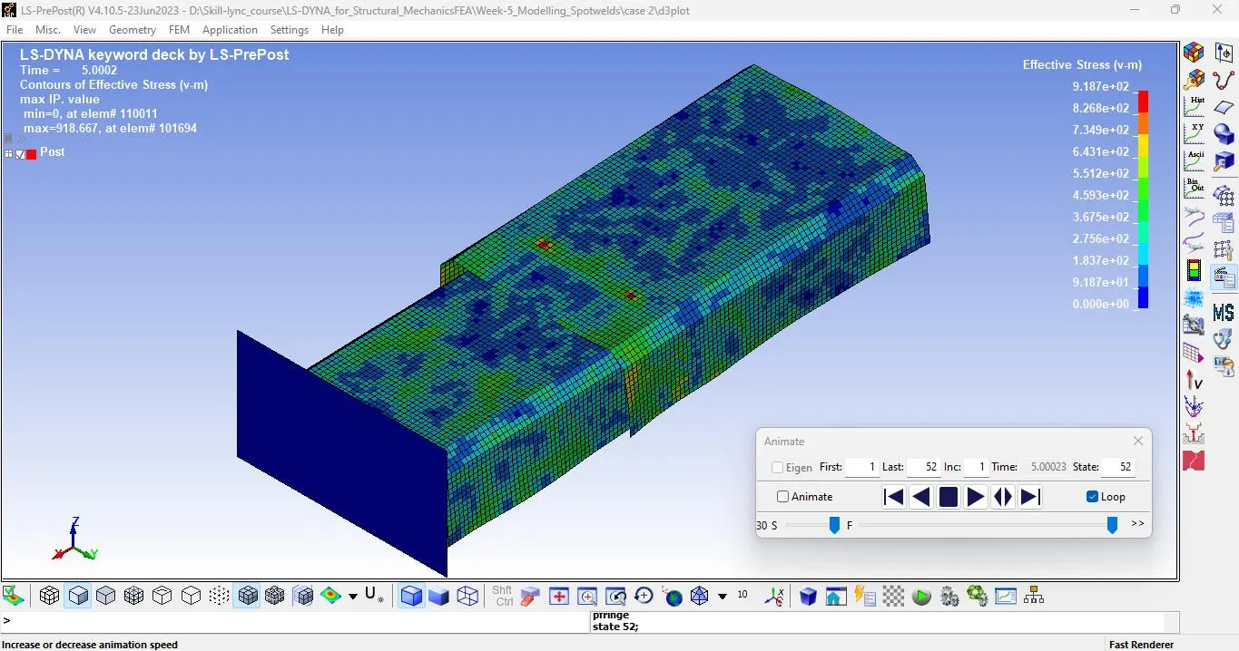
VON MISSES STRESS:-
SOLID ELEMENT (HEXA) CASE : 02
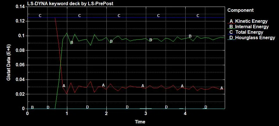
ENERGY PLOT:-
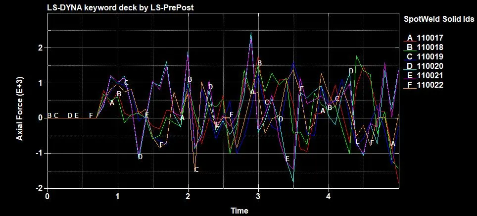
AXIAL FORCES:-
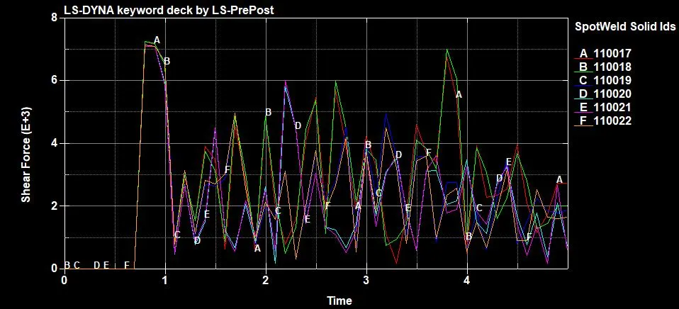
SHEAR FORCES:-
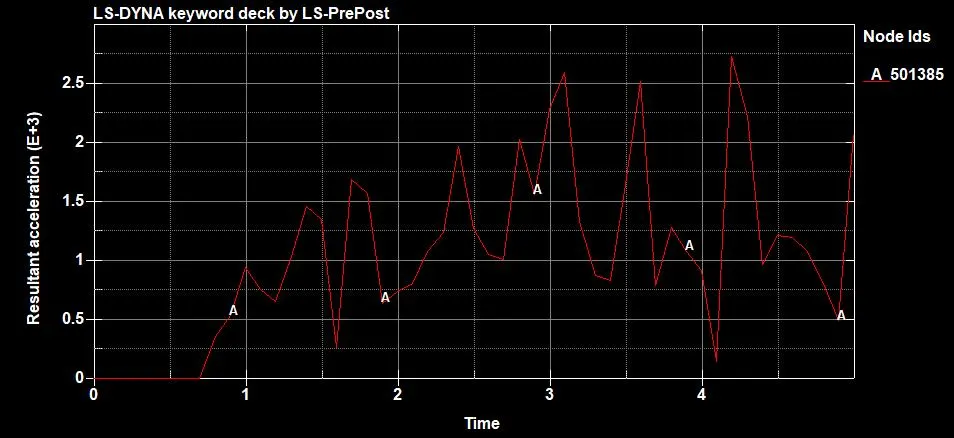
RESULTANT ACCELERATION:-
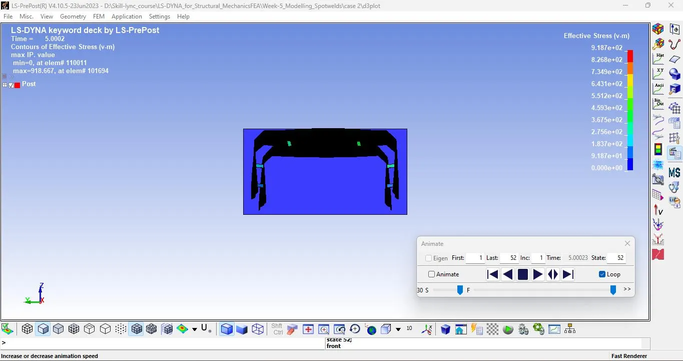
VON MISSES STRESS:-
CONCLUSION:-
We have Model Two types of Spot weld in the sheet metal separately and compared the results.
The Spot weld failure criteria values were calibrated according to the failure at half of the termination time.
As we saw The Solid element spot weld experiences more stress than the beam Element and The Internal energy of the Solid element is much higher than the beam element.
we can also conclude from the result that the solid element is stiffer than the beam element and offer great resistive force against the loss.
So the Solid element is preferable for a realistic condition.
NOTE: LS-DYNA FILE is too big to upload in website. So, I shared the google drive link to download.
Download link : https://drive.google.com/drive/folders/1xT9Ul_lykM0ZaBxoSTOI0Q_7ADCpr7Aj?usp=sharing