Week - 5 - Modelling Spotwelds
Week 5 - Spot weld modelling
Aim
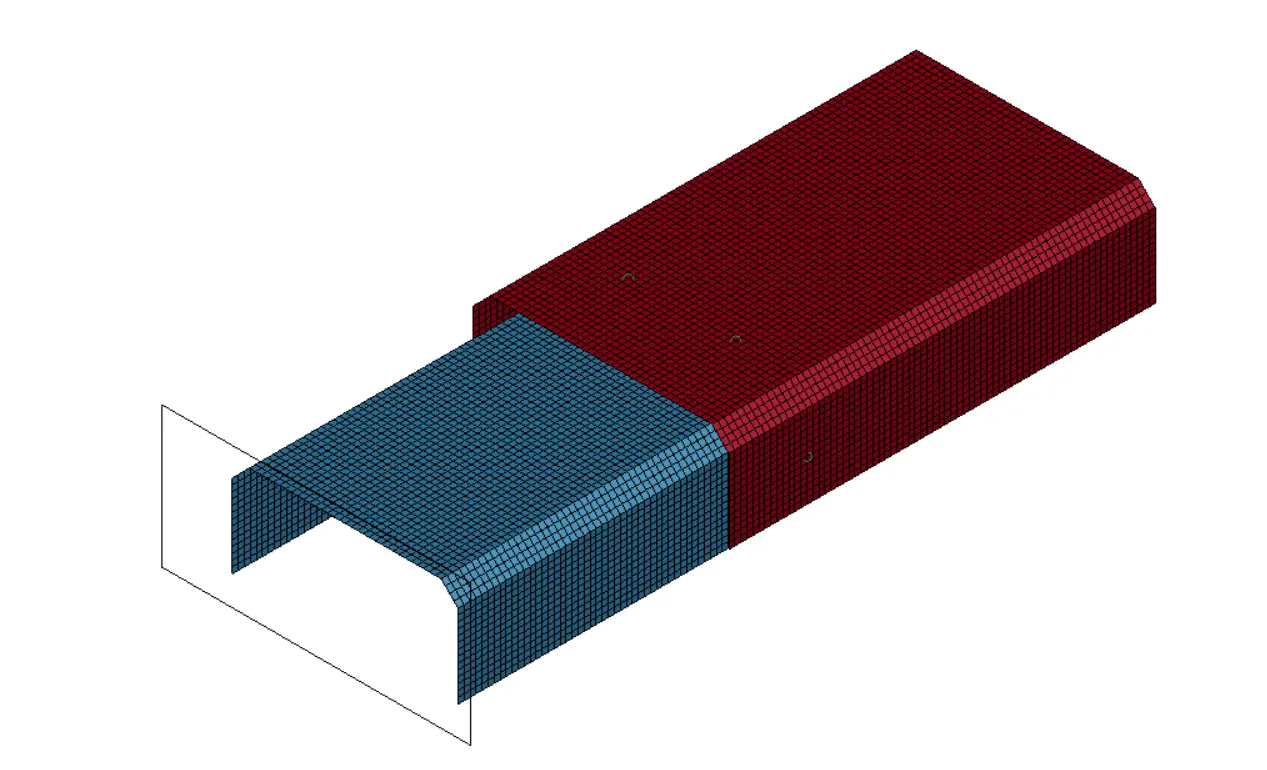
Run a crash box simulation using beam spotweld and solid hex spotweld and compare the results (axial and shear forces)
Explanation
- Modelling of spotweld is very important as it helps as helps to keep thin sheet metals together.
- Material modelling and its failure methods are very important parameters which needs to be considered while simulation
- In Ls Dyna there are 4 methods to model spot welds they are using beam elements and tied contact; contrained spotweld ; generalised constrained spotweld ; solid hex and contact spotweld
Procedures
- intial velocity of 13.889mm/ms is applied along the x axis along with rigid planar wall with normal facing in the oppposite direction for both the cases.
Beam spotweld creation
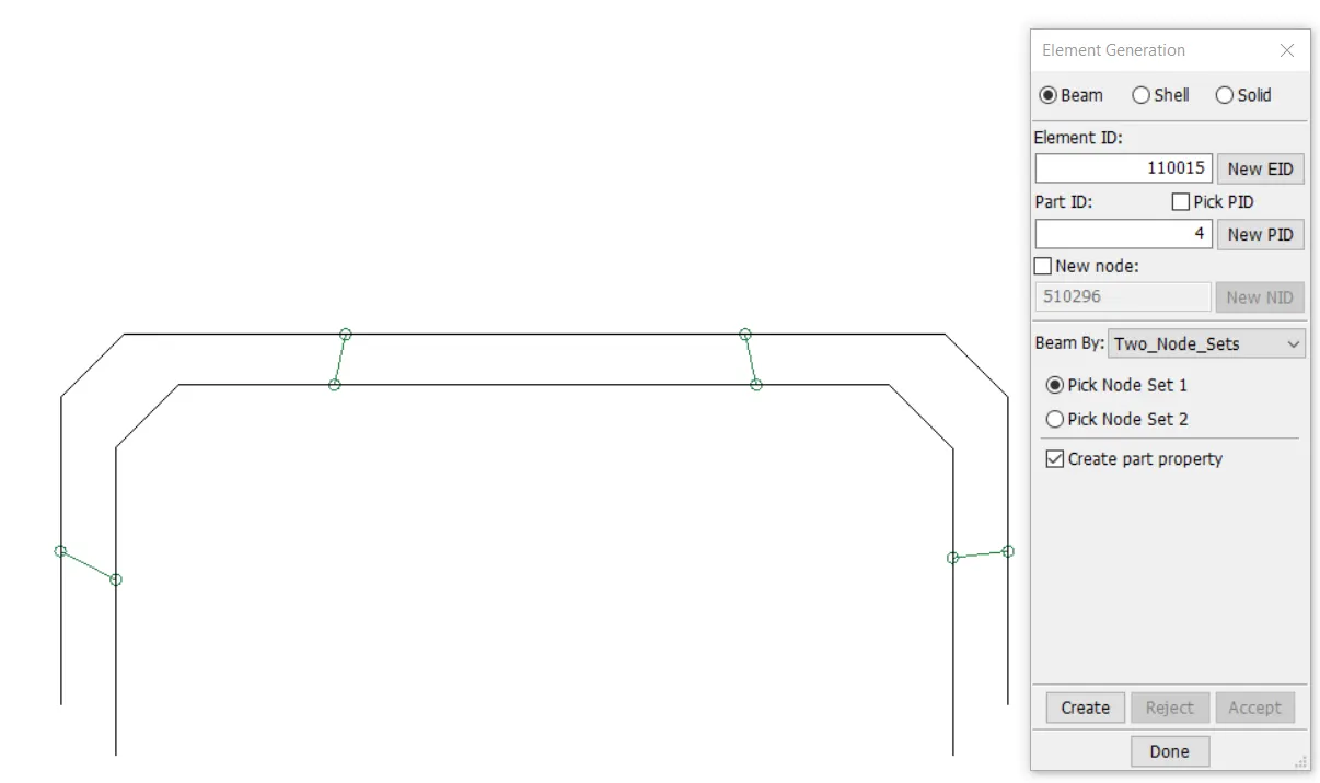
- Using Mesh > element generation > beam elements can be created between two sheet metals > Pick the 2 nodes for beam element creation
- Assign material Properties to the beam elements > Keyword MAT SPOTWELD 100 and enter material properties , methods to fail the weld, also create material properties to the sheetmetals
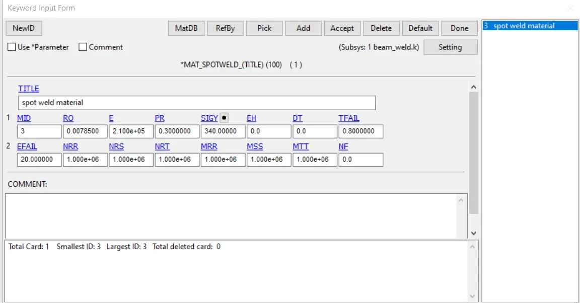
- For this 4 beam elements tfail (time for spotweld to fail) is created at 0.8ms.
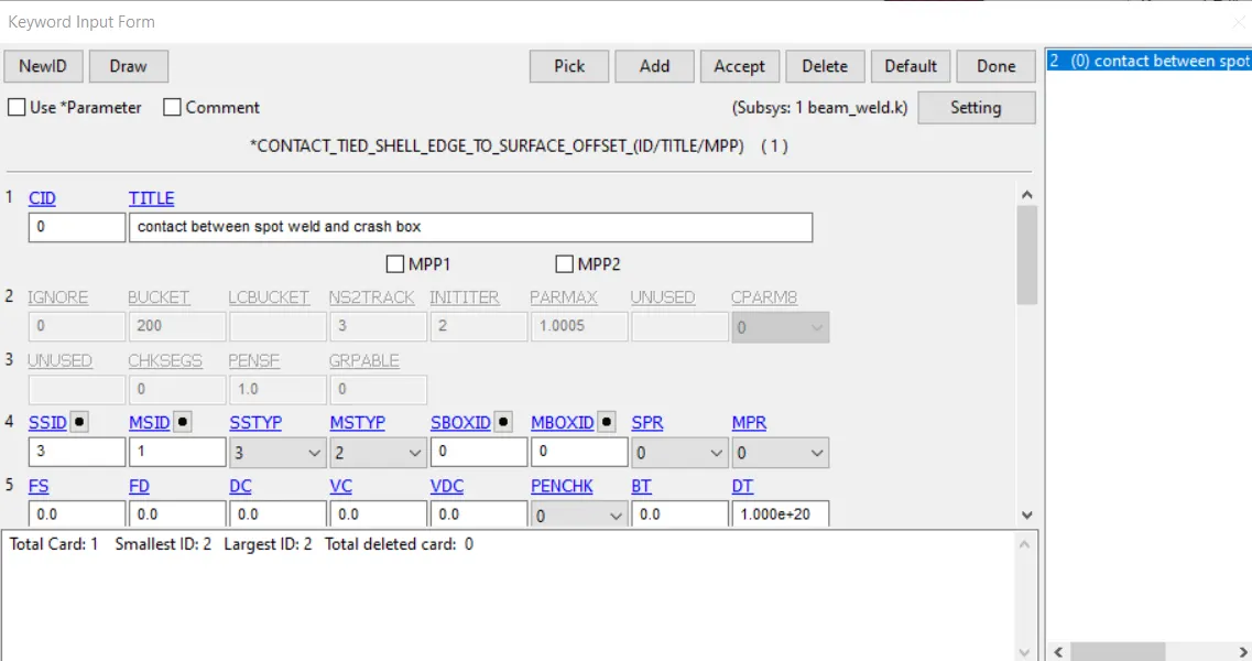
- Create self contact for the sheetmetals as well create a tied contact for the spotweld where slaves are the beam elements.
- Create section for the sheet metals and element formulation 9 is used to create the spotweld ; also give the cross section to the beam in this case tubular.
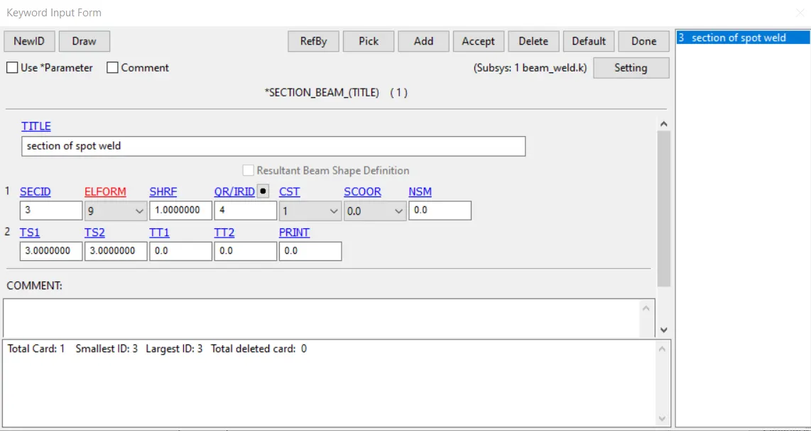
- Assign the material and section card to the beam elements
- Control cards - termination = 1.6ms (impact happens at around 0.8ms) hourglass , energy are created.
- ASCII cards - GLSTAT (global energies) ,SWFORC ( spotweld nodal contraint reaction forces); D3plot are also created for 0.05ms.
Solid spotweld creation
- Using Element Tools > Solid > select the six nodes for hex element creation.
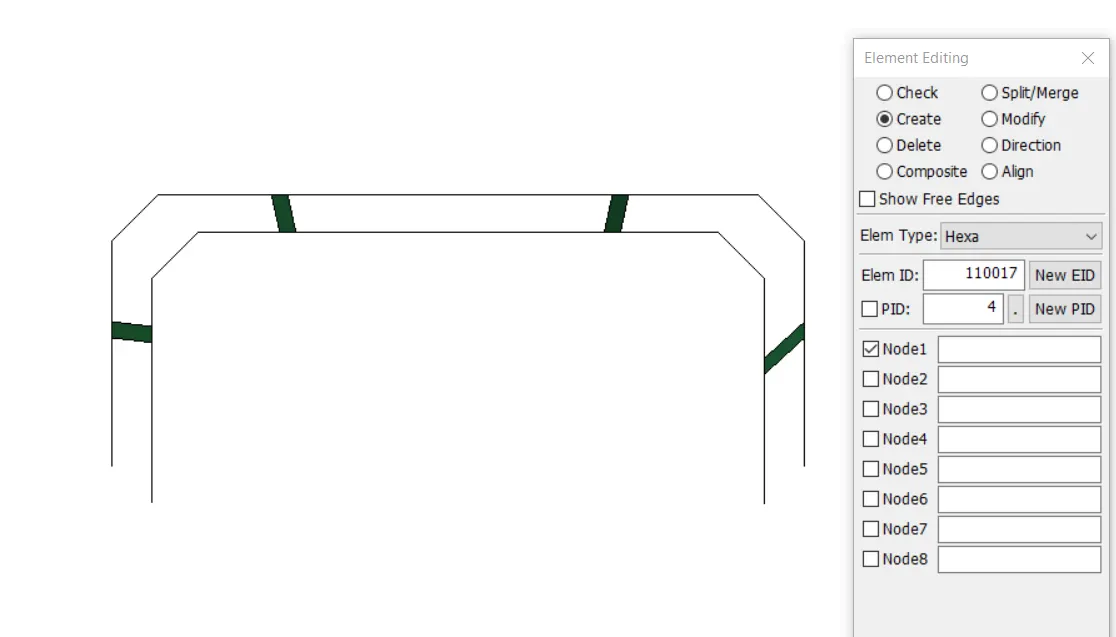
- Assign the material properties to the solid elements > again mat 100 is used ( the same values are used as in beams)
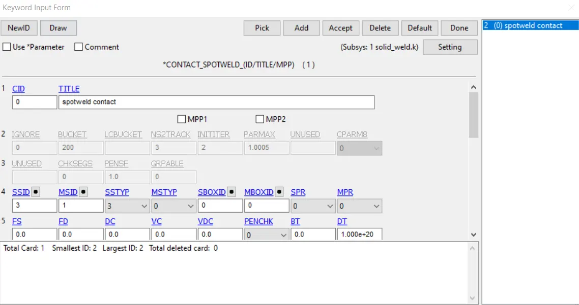
- Create contact spotweld for the solid elements (slaves) and sheet metal as master
- Create section with element formulation as 1 for the solid elements.
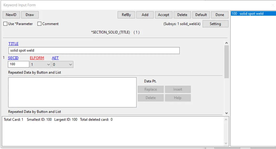
- Assign the material and section card to the solids
- The same control cards and ASCII cards are created for the solid spotwelds
Results and comparison
- Global energies
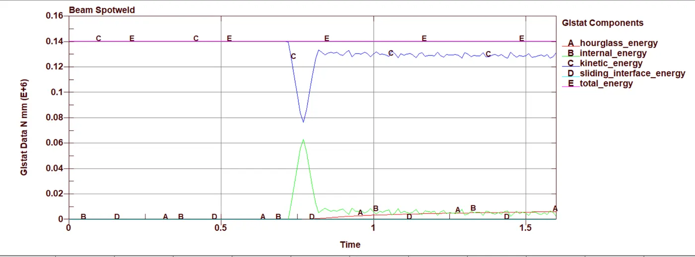
Beam Spotweld
Solid weld
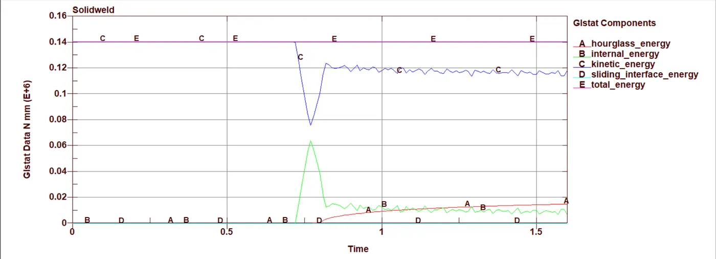
- From the global energy plots Internal energy and kinetic energy plots similiar in both the beam and solid welds. But the hour glass energy in case of the solid can be seen increasing after the impact.
Von mises Stress
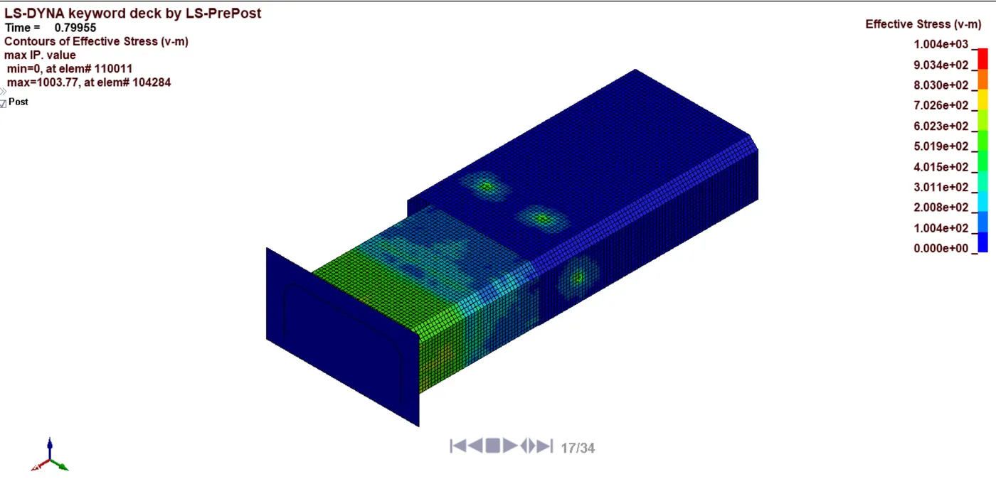
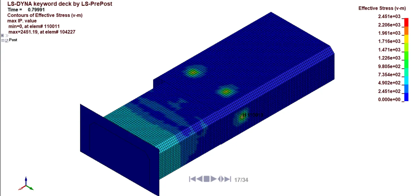
- At the time of impact we can notice a comparatively higher von mises stress in the solid welds that the beamwelds at the time of impact.
Beam weld
Solidweld
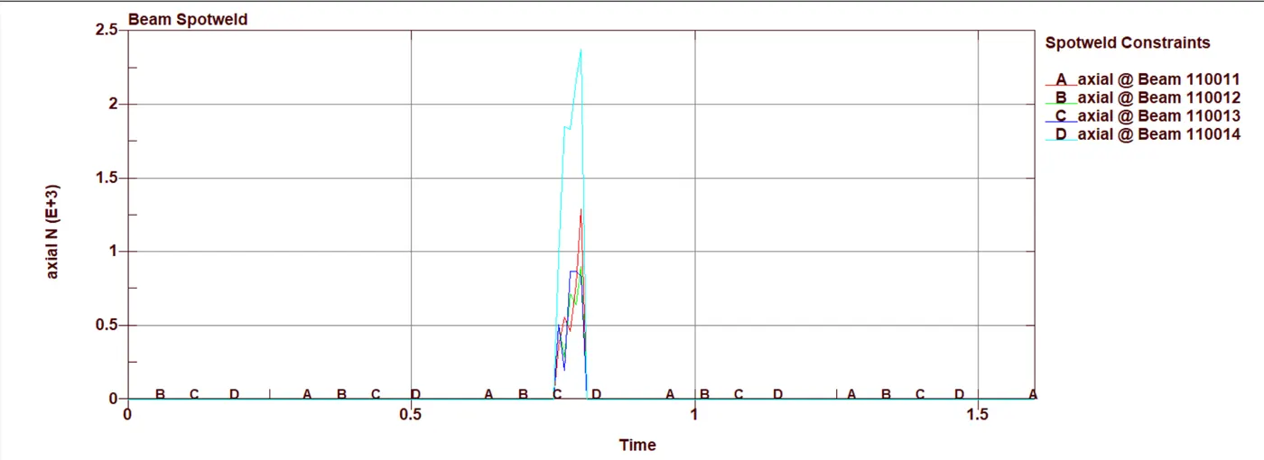
- Axial Forces developed in the welds
Beam weld
Solid weld
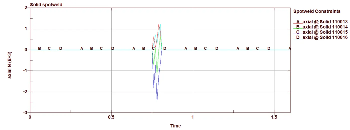
- we notice that some of the solid welds undergoing compression before failing at tfail 0.8ms ; beam welds are under tension load(higher in magnitude than solid weld )before they fail.
Shear force
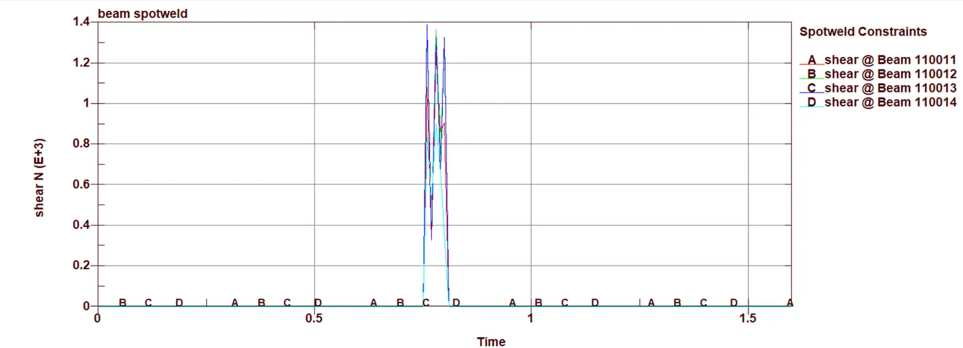
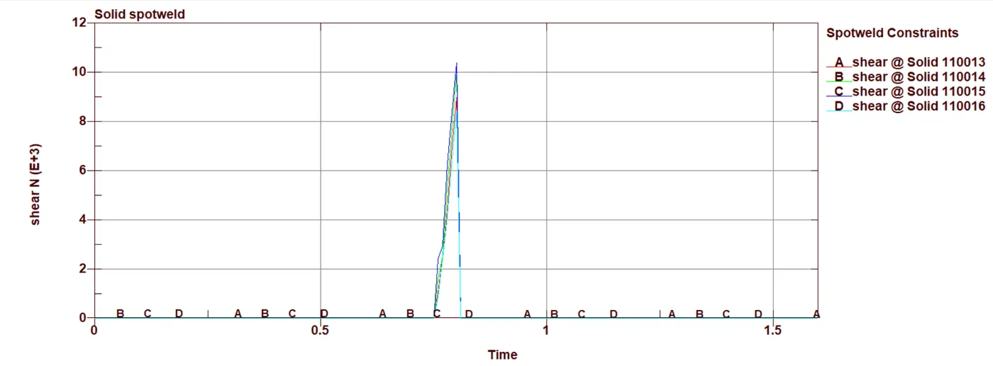
- Solid welds holds more shear forces more than beam welds before they fail at tfail
Conclusion
- Solid weld and beam weld modelling were simlulated
- We could notice difference in the forces generated before the failure.
- Most often when the actual material failure data is not available , user can try tfail for finding out the actual plastic strain, Axial force , shear force , moments which can cause the weld to fail by altering the parameters in the material card spotweld 100, this data can be later used for similiar welds in the future.
Drive link for the files- https://drive.google.com/file/d/1yTVvie-TzW_okN3OgA0xHpXfg_Pbd7cI/view?usp=sharing