Week 5 Bending of iPhone
- Objective:-
To simulate bending of a phone body by holding ends of the phone using four fingers and applying bending force in the middle using thumb, and find stress and displacement data in ANSYS software.
- Model Details:-
For the current study, a model has been given as shown below,
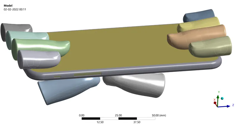
In this model, we have the phone being simulated in three parts namely, Frame, Display and Inside for simplicity. We can see the four fingers on each end of phone restricting the Y-axis displacement and two thumbs at the bottom applying the bending force.
Applied materials for Frame is Aluminium alloy NL, for Display Glass (with custom suitable properties that of glass) and for Inside Polypropylene. All the fingers except the right thumb is treated as rigid body. For the Case-2, I have added the given S-N curve for the aluminium frame, for the fatigue analysis and life of the frame results.
For mesh, Mesh Sizing is applied only on bottom surface in contact with the thumbs and each contacting surface of the tumbe is selected with element size of 4 mm. Rest of the model is meshed with a default element size.
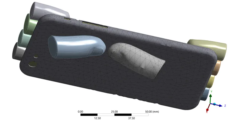
In Case-2, the bottom two thumbs are shifted to the centre of the phone (both thumbs are shifted by 22.5 mm and 10 mm in X and Z direction respectively)
- Loads and Constraints:-
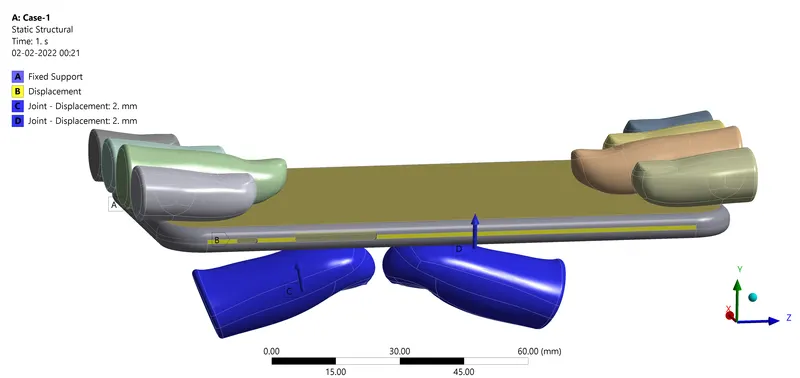
End surfaces of the phone are applied with Fixed support so that phone does not slip off during simulation and the side flat surfaces of the phone are restricted with displacement only along Y-axis. The two thumbs at the bottom are given Y-axis translation of upto 8mm in 4 seconds and again back to original position in next 4 seconds.
- Results:-
Case-1:
Directional Deformation of Frame at the end (after the retraction of thumbs) = 5.4416 mm (Permanent plastic deformation of Frame)
Animation link of the Directional Deformation of the frame:- https://youtu.be/mWfeKOPEwi4
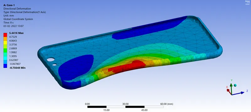
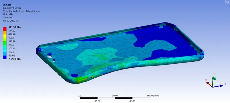
Max. Equivalent stress generated = 611.97 MPa
Max. Force reaction at the thumbs to cause this deformation = 35734 N. In the plot, the importatant force is the Y-direction reaction force, which is forcing the thumbs into causing this deformation to the phone. Y-direction force is plotted in 'green' line, and total force in 'purple' line. As the Y-direction force is major, the green and the purple lines overlap in the plot below.
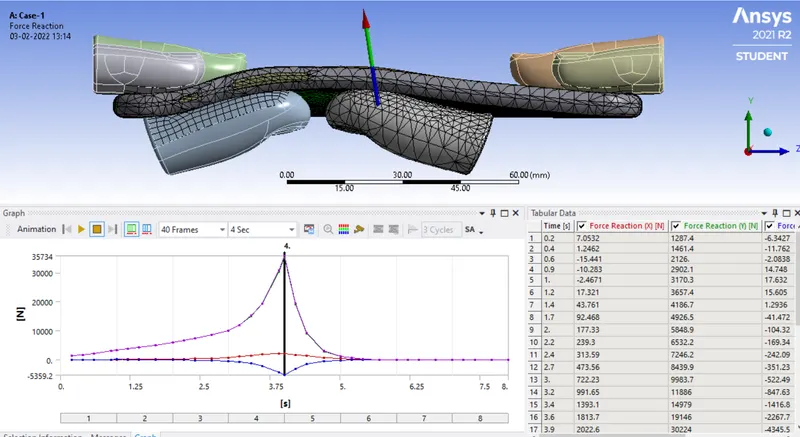
This shows that the for Case-1, thumbs would need maximum of 35734 N force to push against the frame by 8 mm.
Case-2 (thumbs in the centre, fatigue analysis of the frame):-
Directional Deformation of Frame at the end (after the retraction of thumbs) = 4.4694 mm (Permanent plastic deformation of Frame)
Animation link of the Directional Deformation of the frame:- https://youtu.be/msocjfcsgU8
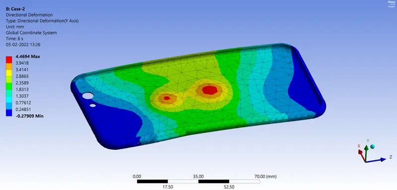
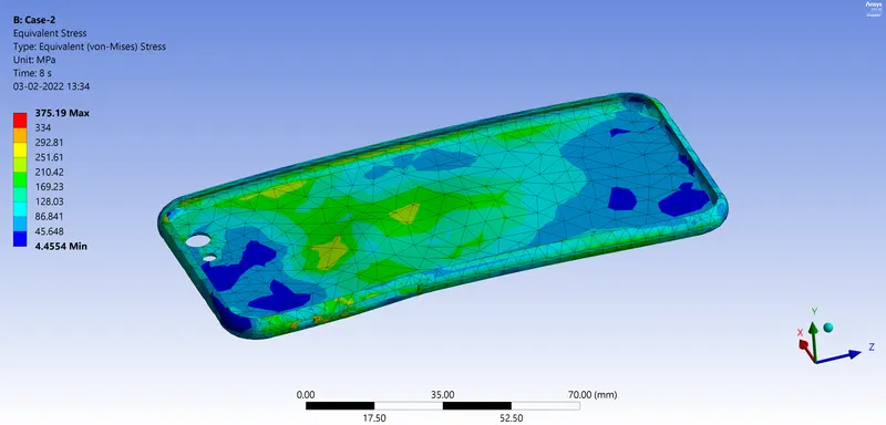
Max. Equivalent stress generated = 375.19 MPa
Max. Force reaction at the thumbs to cause this deformation = 19291 N
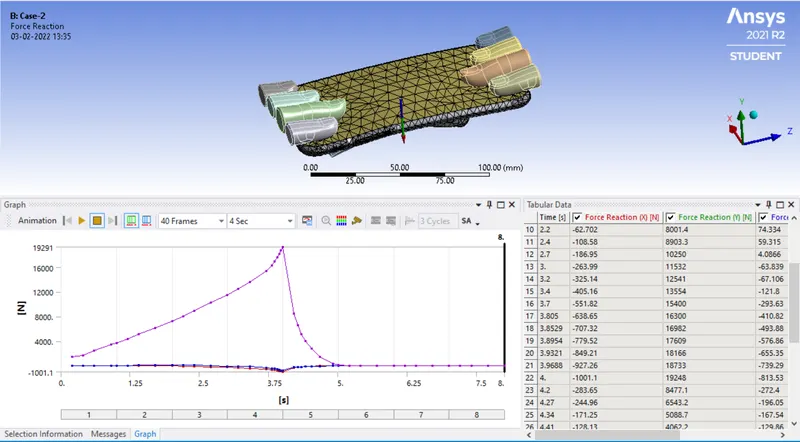
This shows that the for Case-1, thumbs would need maximum of 19291 N force to push against the frame by 8 mm, which is almost half than that of Case-1.
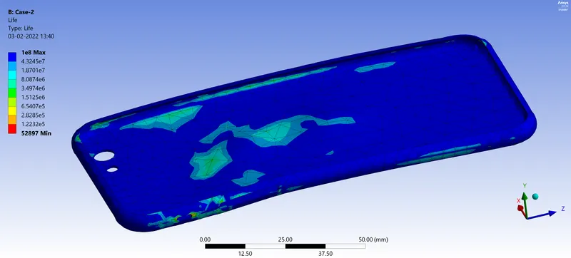
By supplementing the given S-N curve into frame material, we can evaluate the life of frame. As our loading starts with zero and reaches maximum stress and goes back to zero, I have selected 'Zero-based' type of loading in the Fatigue tool (instead of 'fully reversed' which means that phone is bend in up and down both the direction, which is not the case.)
Min. life of the frame from fatigue analysis = 52897 cycles
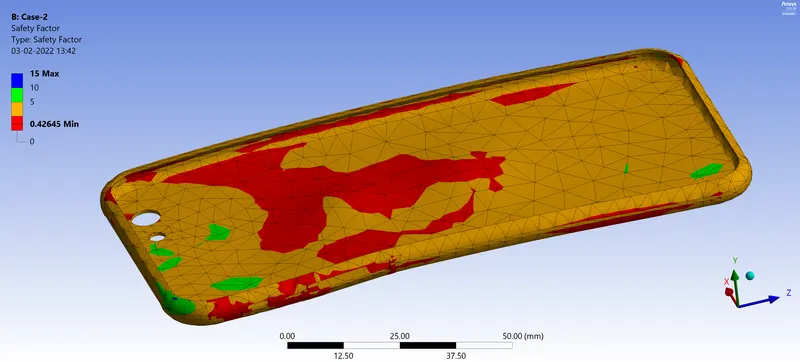
Min. factor of safety of the frame for design life of 1E+9 cycles = 0.42645
- Conclusion:-
In summary we can conclude that we have successfully simulated the bending of i-Phone in both the cases and obtain the directional deformation, equivalent stress and fatigue life of the frame.
It is clear that the force required by the thumbs in Case-2 is much lesser than that required in Case-1 (almost half). This is because the amount of travel for both the cases is same, but in Case-1, thumbs are pressing near the edge of the phone, where the frame structure is relatively stronger by presence of bends. While in Case-2, thumbs are at the centre of flat frame, and so this part is relatively weaker than the edges, so thumbs requires less effort during their travel. Hence also the stress generated in Case-1 is much higher than in Case-2, due to higher resistance to the motion.
Also we have obtained the fatigue life of the frame of around 52897 cycles.