Week 5 Bending of iPhone
AIM :
To Performing the simulation for Bending the Iphone model according to the case requirements.
OBJECTIVES :
Adding the appropriate Materials for the model.
Assigning the appropriate material to the respective component.
Create a Connection Contacts & Joint to the model where it's required.
Discritize the Model.
Applying the Boundary Condition.
PROCEDURE FOR ATTAINING THE OBJECTIVES :
I) CAD Model :
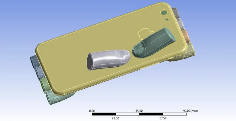
A Iphone model is given from design team. We have to import that model file through the Geometry selection option and followingly check the component whether its proper one or not. A given model is proper, there's no any geometrical errors are presented. But we have to change the position of the bottom finger based on case requirement in ANSYS Spaceclaim.
Once we done this,Our models are looks like as shown in below images.
CASE 1 :
CASE 2 :
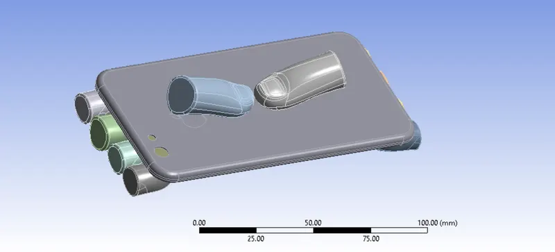
We have to change the bottom two finger from initial position to another position according to the coordinate which given by X is 22.5 mm & y is 10 mm.
Once we changed the position of the bottom two finger, it has been looks like as shown in below image.
II) Material Adding and Assigning :
In this model have consists of four different main parts which are Fingers, Frame, Inside parts and then Display. We gonna use materials based on a parts which we have in the Iphone.
Make sure we have to keep "Rigid" as a stiffness behavior for all fingers expect one bottom finger. It will keep as Rigid while performing the simulation on those fingers.
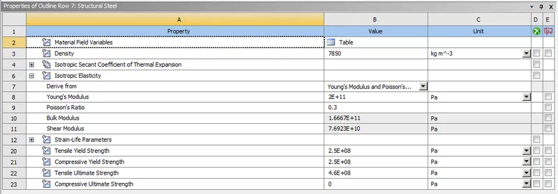
Structural Steel :
A Structural Steel material is assigning to each & every finger.
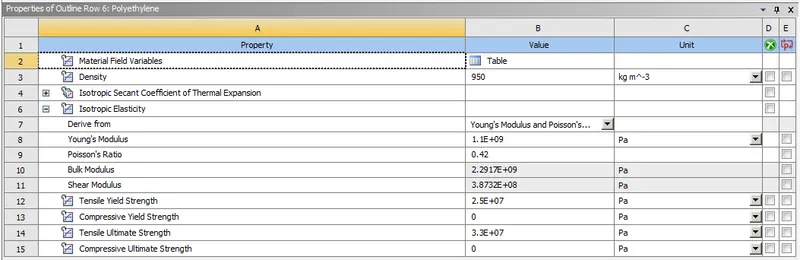
Polyethylene :
A Polyethylene material is assigning to Iphone Inside parts.
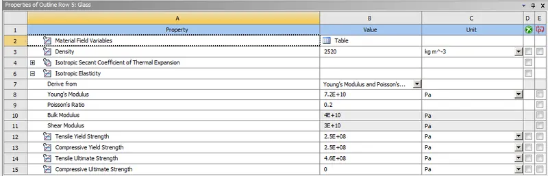
Glass :
A Glass material is assigning to Iphone Display.
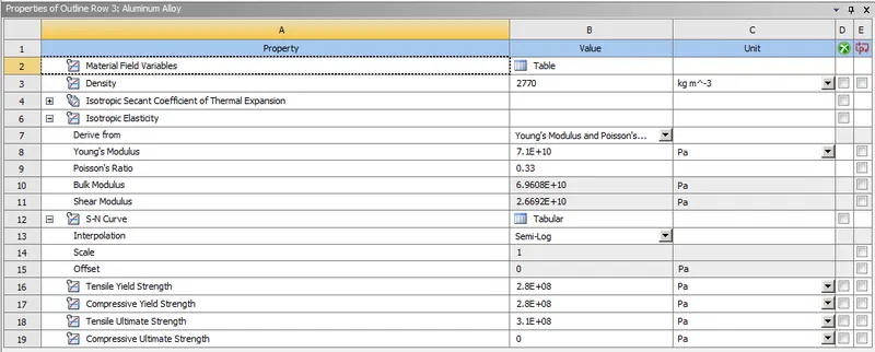
Aluminium Alloy :
A Aluminium Alloy material is assigning to Iphone frame for Case 1.
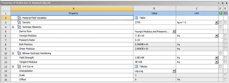
Aluminium Alloy Non Linear :
A Aluminium Alloy Non Linear material is assigning to Iphone frame for Case 2.
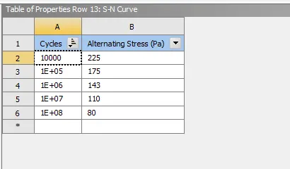
Before going to assigning the material to the respective component. Make sure we have to defined the alternative stress and also defined corresponding cycles while adding the materials in the engineering data section.
III) Connections :
i) Contacts :
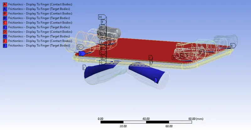
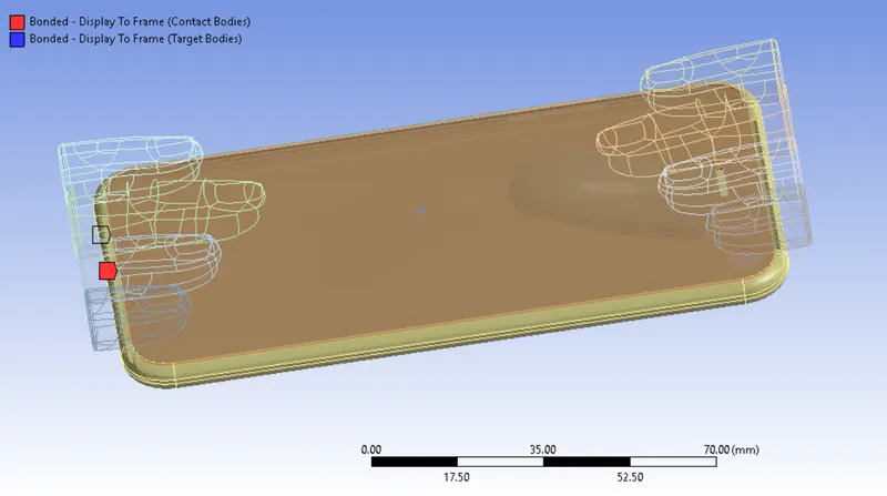
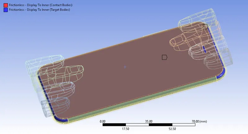
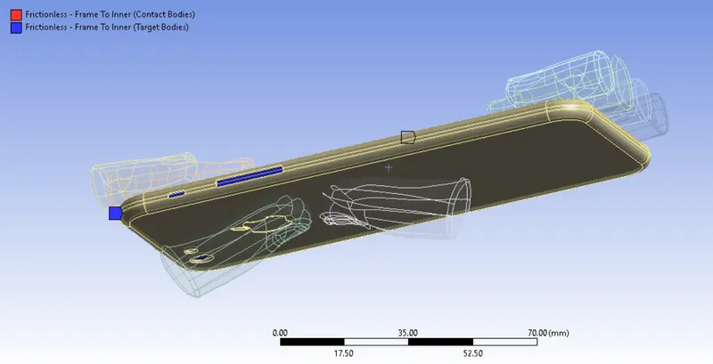
In this Iphone model simulation, we have to create a two different type of contacts which are Frictionless & Bonded type.
A Frictionless type of contacts are used for "Display to Fingers", "Display to Inner", "Frame to Inner".
A Bonded type of contact is used for "Display to Frame".
Keep default settings as it is for both type of contacts.
Contacts between Display to Finger :
Contacts between Display to Frame :
Contacts between Display to Inner :
Contacts between Frame to Inner :
ii) Joint Connections :
Fixed :
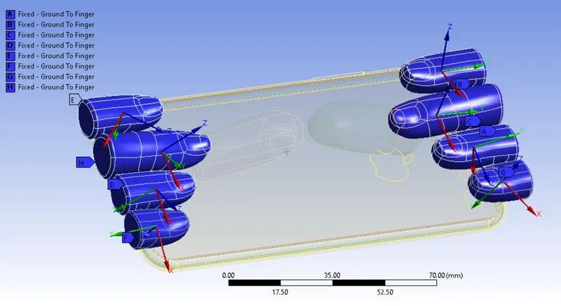
All Finger should be fixed except bottom fingers while performing a simulation.
A Connection type is Ground to Body for all Fixed joints.
Once we done the fixed joints on the fingers, it has been looks like as shown in below image. It will not tends to move on any direction while performing the simulation.
Translational :
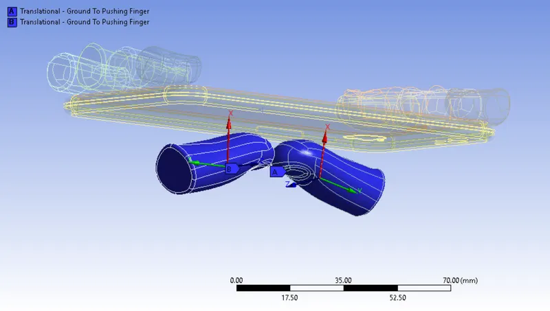
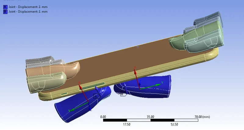
Similarly, we have to Create a Translational joints for the bottom two fingers.
Keep "Ground to Body" as a Connection type of this joint.
Make sure check the coordinate direction.
Once we made the translation joint, it has looks like as shown in the image below.
IV) Meshing :
Basically, To divide the entire model into infinitesimal control volume, that frame work is called Meshing. This process is called Discritization. This FEM is widely used for solving partial differential equation in different physical field such as Structural problem, Heat transfer problem, Fluid flow problem, Electro magnetic Analysis & Acoustics Analysis.
Face Sizing between bottom finger and Display :
Select the bottom finger contact face & Display top face and meshing with 4 mm size of the element.
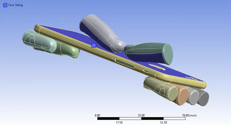
Number of Nodes = 22694
Number of elements = 10656
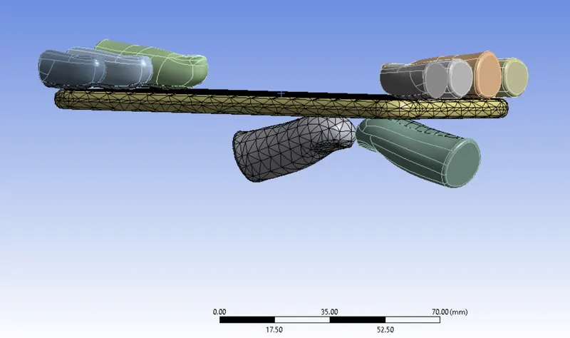
A Flexible components are meshed with Tetrahedral elements.
A Rigid component like fingers are only done by surface meshing alone with mixed type of elements.
After done the meshing, it has looks like as shown in below image.
V) Analysis Settings :
Number of Steps is 8 and we gonna perform with multi step from where 1 to 8.
Solver Type is Direct.
Keep "Program Controlled" for Weak Springs.
Keep switch to ON for Large Deflection.
Change into "Constant" for Stabilization and method as energy.
Energy Dissipation Ratio is 0.1.
Switch to "Yes" for Activation for first substep.
Stabilization Force Limit is 0.2.
Change into "Yes" for all which are comes under the Control output settings.
Boundary Condition :
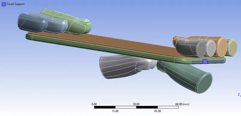
Fixed Support :
Inorder to hold the inside components while performing an bending simulation, we have to fix the faces on both sides as like in below image.
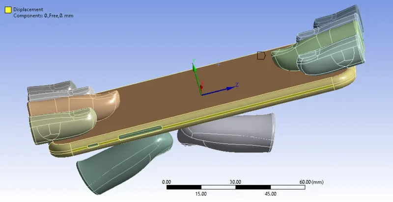
Displacement on the Frame :
While performing the bending simulation, a Iphone should only tends to move on along the Y direction. Inorder to avoid the movement on the X & Z direction, we have to constraint on both direction by using displacement joint.
Displacement for the Bottom Finger :
Select the one of the bottom finger first & Select displacement as a Type of joint.
Inorder to bending the Iphone model, a bottom finger should be move on Positive X direction upto 8 mm and return back to origin position.
On first four steps, a finger will move from 0 to 8 mm and then remaining four steps, a bottom finger will move from 8 to 0 mm.
Once, we created the displacement joint for one finger. similarly, we have to do on another finger.
RESULTS :
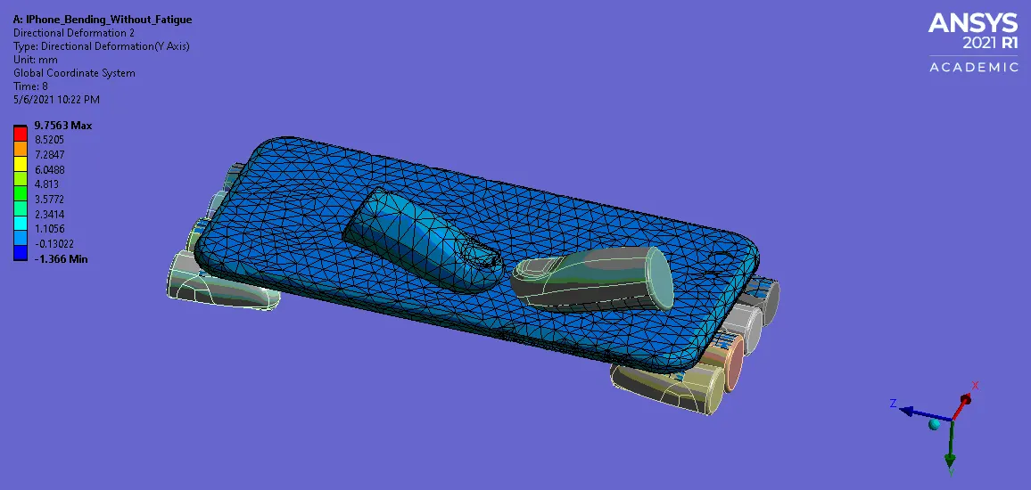
Case 1 :
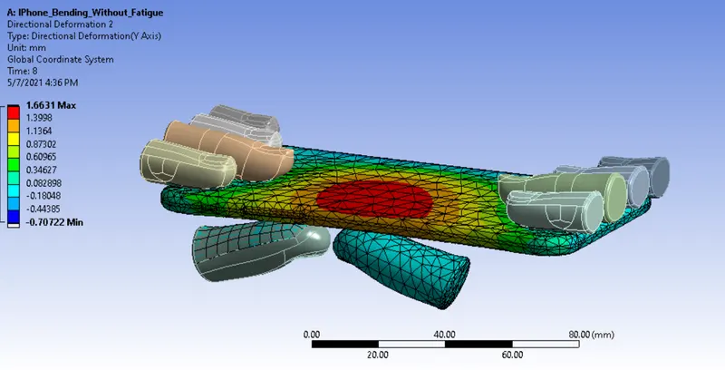
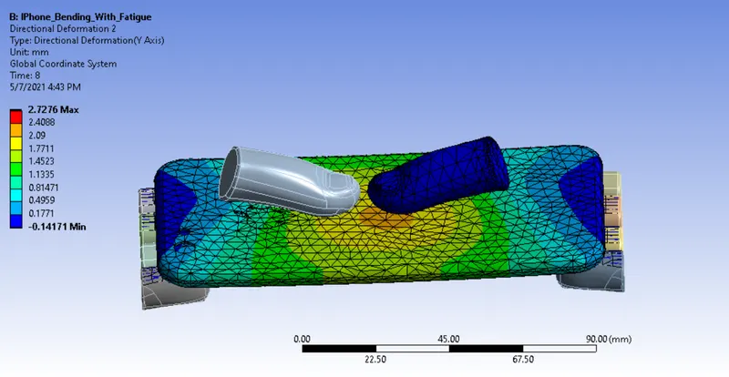
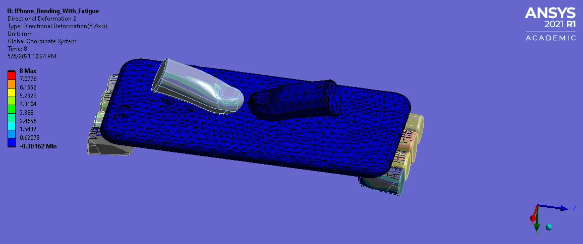
Case 2 :
CONCLUSION :
A Maximum deformation is around 1.6631 MPa for Case 1 and 2.7276 MPa for Case 2. A Case 2 directional deformation is slightly more than Case 1 due to changing the position of the bottom fingers at center of the iphone.
After removing the applied load from the iphone model for both cases, a iphone couldn't be comes to original position which means, a iphone would be attains permanent deformation.
A Factor of Safety is 1 for Aluminium Alloy, a factor of safety is less than 1 for Aluminium Alloy Non linear. So, according to the factor of safety results We shouldn't preferred this materials for Iphone Frame.
For Case 1, it have 1e+8 number of cycles and Zero cycles for Case 2. So, according to the cycles We can choose Aluminium alloy as a material for frame.