Week 5 Bending of iPhone
PHONE BENDING SIMULATION
OBJECTIVE
To perform a benging of a phone simulation using ansys with two cases with two different positions where the load acts and to study the effects of strain, stress and displacement along with the fatigue life and FOS of the component
PROCEDURE:
- Create a new static structural simulation
- IMport the polyurethane material for the plastic inner comp and glass for the display and finally al alloy to model the frame.
- Import the geometry file onto the Spaceclaim GUI.
- Then the model module of static structural is again updated.
- Open the model in ansys mechanical module.
Material assignment
- polyurethane material for the plastic inner comp
- glass for the display
- al alloy to model the frame.
Contact region
- Specify the contact between all the fingers at top to the display as rigid. Since they are considered rigid they wont be meshed since no displacement has to be computed over the comp region
- Unlike the fingers, the tuumb parts are kept as flexible such that any deformation could occur in the thumb needs to be studied or just visualized
Mesh
- Use a sizing of 4mm at the contact regions between the thumb and frame
- The rest of the comps are meshed w a target length of 7mm
Fixed Joint
- Select a single face in all fingers and click on extend - connections to select all faces of the finger component
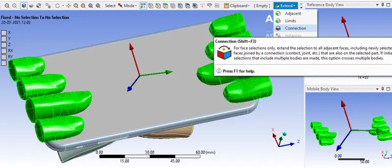
NOTE: The above function must be done for each individual finger separately.
Joint load
- A displacement is defined on the two flexible joints defined on the thumbs along the x direction. This displacement is increment to the mid period of the time step and reverted back in case any plasticity or definite fracture that occurs in the phone can be clearly visualized.

Analysis settings
- A total of 8 time steps are created which defines that the load will be gradually applied and retracted after the 5th time step.
- Large deflection = on
- Direct solver
RESULTS:
CASE 1
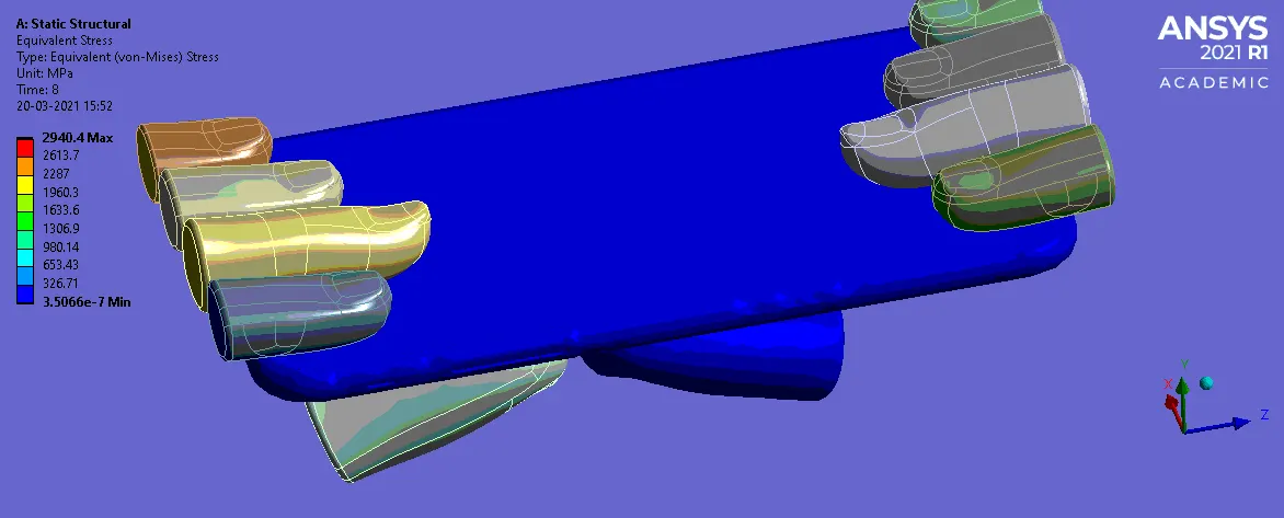
Equivalent stress
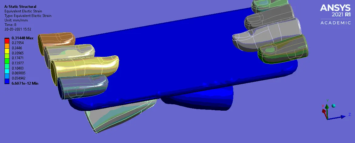
Equivalent strain
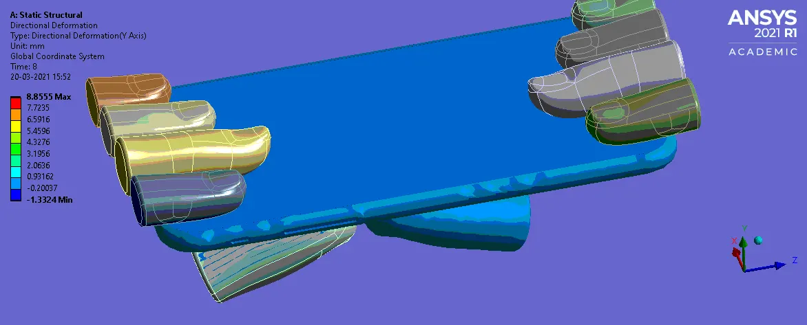
Directional deformation
CASE 2:
Move the thumbs to the given position X= 22.5mm & Z= 10mm using Spaceclaim / Design modeler
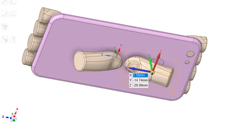
Then the SN curve for the frame (al alloy ) material is defined in engineering data
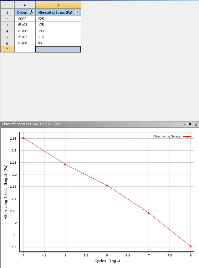
The simulation is run again.
The following results were obtained
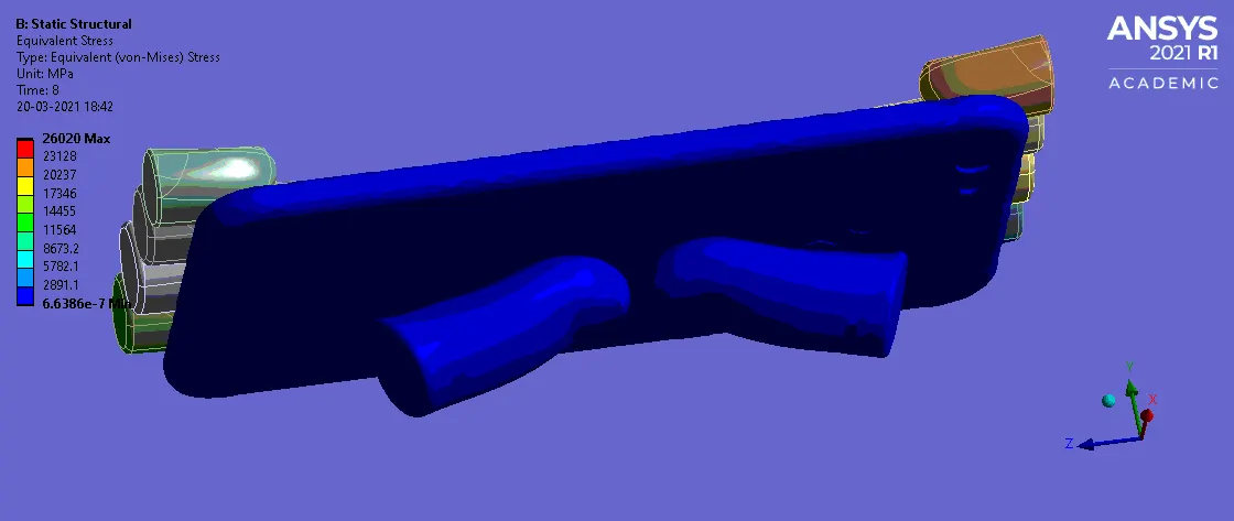
Equivalent stress
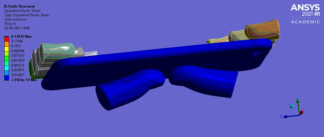
Equivalent strain
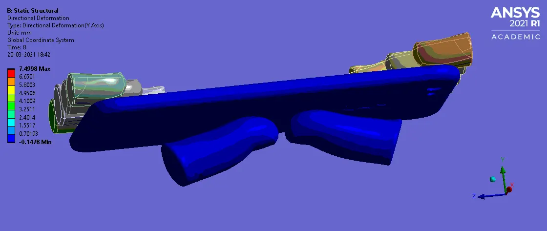
Directional deformation
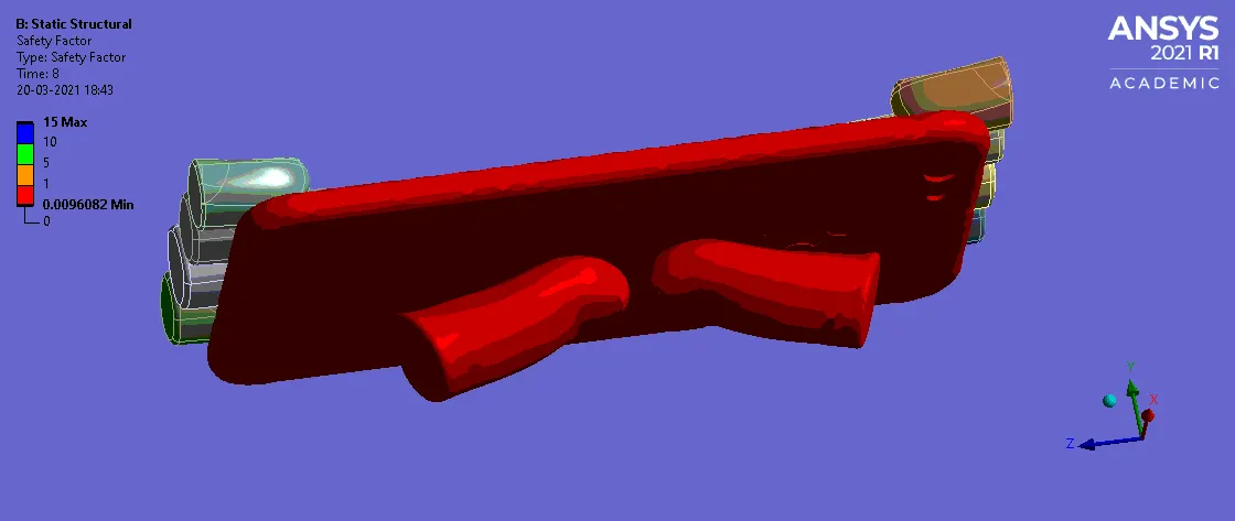
Factor of safety
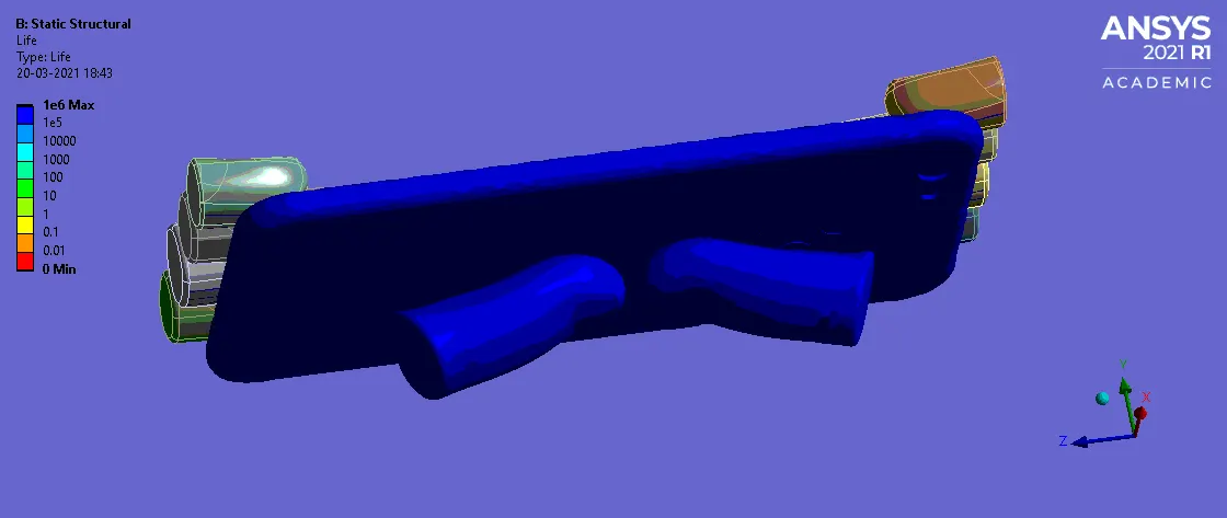
Life
CONCLUSION
Hence the bending of a phone simulation has been performed and the results for equivalent stress, strain and directional deformation were extracted. From the results we can conclude that the stress generated in case 2 is significantly higher when compared to that of case 1.
While the directional deformation is high in case 1 since the force is applied at the edge and hence the force distributed over a small concentrated area has a adverse effect on the directional displacement unlinke in case 2 where due to a large surface area (since the concentrated force is at the centre) the force distribution in even over the entire surface hence the displacement achieved is quite low.