Week 5 Bending of iPhone
iPhone bending Report
Aim: For this challenge, simulate the bending of iPhone as per the given cases below:
- Case 1: Simulate the model as it is given in the video
- Case 2: Move the bottom fingers from their defined position to the given position X= 22.5mm & Z= 10mm and obtain the results for the simulation. Also define the S-N curve for the Aluminium Alloy material as per values given below and determine the fatigue life results for the same.
|
Stress, MPa |
Number of Cycles, N |
|
225 |
10000 |
|
175 |
100000 |
|
143 |
1000000 |
|
110 |
10000000 |
|
80 |
100000000 |
Results and Deliverables:
- Obtain the directional deformation for the model
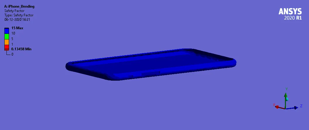
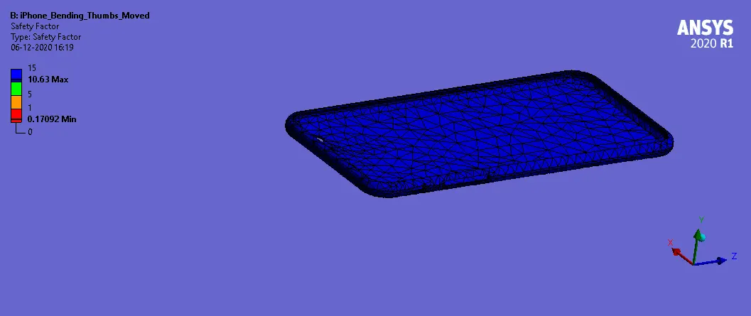
- Factor of Aluminium Alloy NL
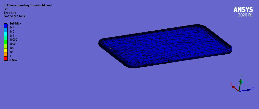
- Life of the Aluminium alloy for the case
- Compare the results and present with the conclusion.
Procedure:
- Select Static Structural, drag and drop into Project Schematic.
- Choose materials Structural Steel, Aluminium Alloy NL, Glass and Polyurethane under Engineering Data.
- Add the given tabular data under SN Curve of Al Alloy in Engineering data.
- Under geometry tab, import the given geometry, double-click to open Space Claim to register the model.
- Then in Mechanical Module, assign Structural Steel to the fingers, Aluminium Alloy NL to the frame, Glass to the display and polyurethane to the insides of the iPhone.
- Assign a bonded connection between the display and the frame.
- The other connections including display to insides, display to fingers, frame to insides, frame to fingers can be left frictionless.
- All the fingers can be assigned a fixed joint except for the pushing fingers (thumbs). The pushing fingers must have a translational joint.
- The mesh size was set to default, and the pushing fingers’ upper faces were given a 4mm face sizing.
- Under static structural tab, we set the analysis to 8 steps with auto timestep as programmed.
- The upper and lower faces (vertically) of the frame are given a fixed support.
- The left and right faces (horizontally) of the frame are allowed a displacement along Y axis.
- Both the pushing fingers are given a joint displacement along Y-axis in 8 steps, ensuring it pushes the frame and retreats.
- Directional Deformation in Z-axis, Equivalent Plastic Strain and Equivalent Stress plots are requested from the solver as outputs.
- Also requesting Fatigue tool gives us life and safety factor.
- Run the simulation by clicking on “solve”.
- Repeat the same steps in case 2, but after moving the pushing fingers by (22.5, 0, 10).
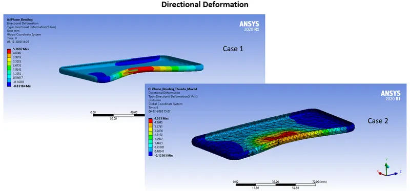
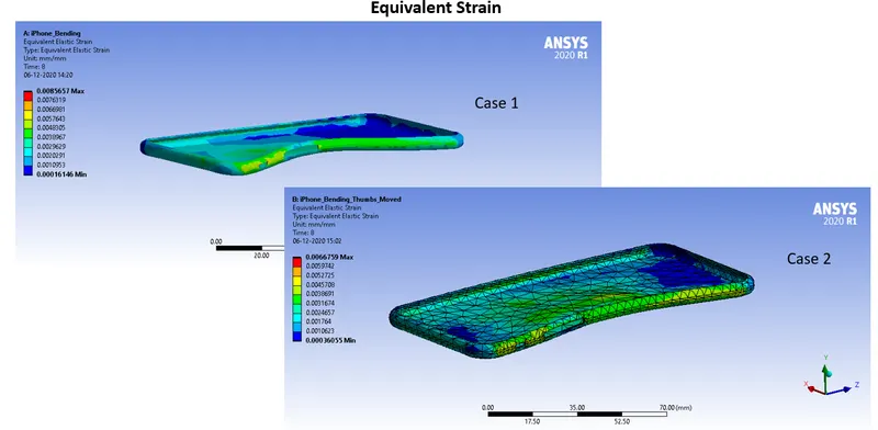
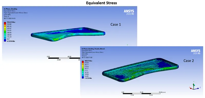
Case 1:
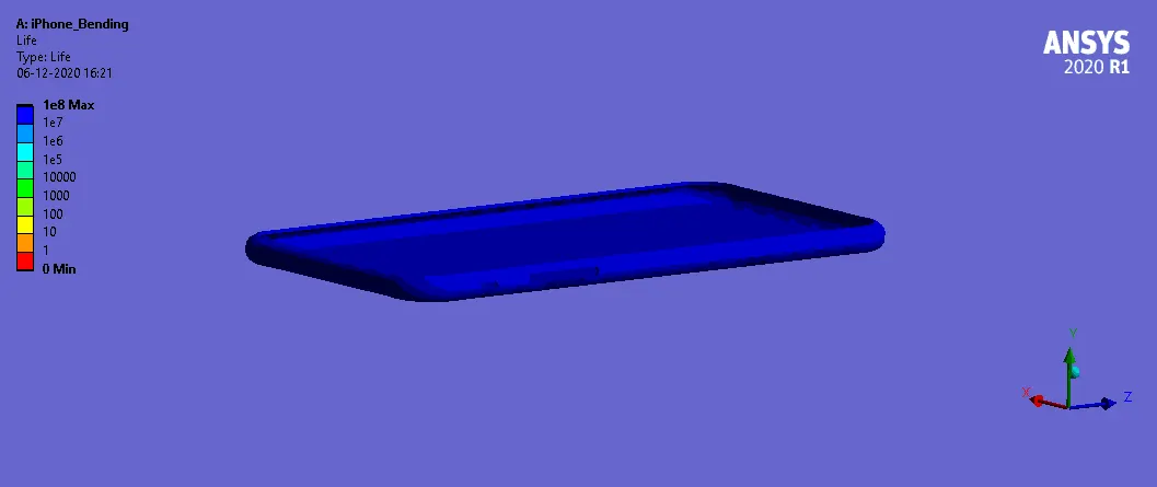
Case 2:
Conclusion:
From the two cases, here is the inference:
|
Case |
Stress in Al-Alloy (MPa) |
Strain in Al-Alloy |
Directional Deformation (mm) |
|
Case 1 |
594.45 |
0.0085657 |
7.9345 |
|
Case 2 - Thumbs Moved by (22.5,0,10) |
468.05 |
0.0066759 |
4.633 |
We can observe that the stress, strain and deformation has reduced after moving the position of pushing fingers.
Safety factor of case 1: 15
Safety factor of case 2: 10.63