Week 5 Bending of iPhone
AIM: - PERFORM THE SIMULATION OF THE BENDING OF AN I-PHONE.
Objectives:
Simulate the bending of the model of an I-phone.
Move the bottom fingers from their fixed position to X = 22.5 mm and Z = 10 mm and obtain the results of the simulation.
Define the S-N curve for the Aluminium Alloy material for the values provided.
Determine the fatigue life results for the same.
To begin with, the analysis, launch Ansys Workbench and select the Static Structural Analysis from the Analysis Systems.
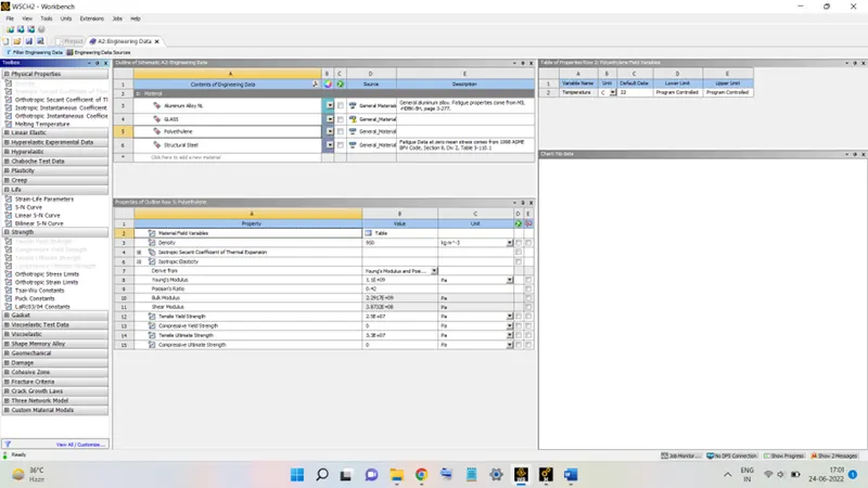
Double-click on Engineering Data, go to Engineering Data Sources and select General Materials and add Polyethylene into the project workspace.
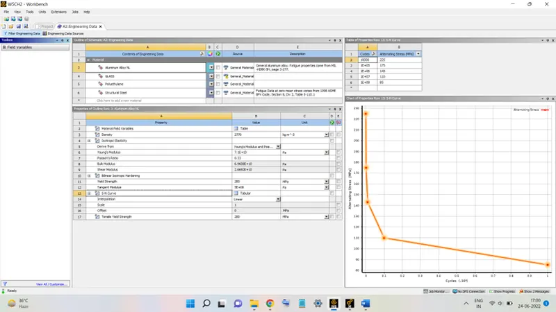
Next, go to General Non-Linear Materials and add Aluminium Alloy NL in the project. To add the S-N curve add the S-N curve quantity in the properties table and fill in the values in the table to generate the plot.
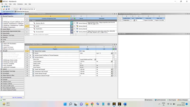
Duplicate the Polyethylene and edit the values of some quantities and rename the material as GLASS. This material now is now having properties resembling those of the Glass.
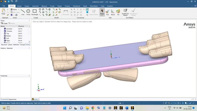
Now, import the geometry into the project environment. The model, in SpaceClaim, will look like this:
Right-click on Model and select Edit to load the model in the Mechanical Module.
in the module, the following steps must be performed to set up the model for the analysis:
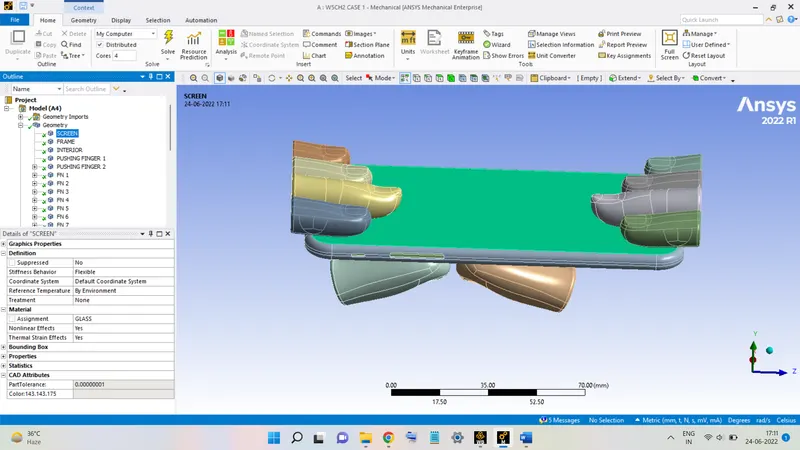
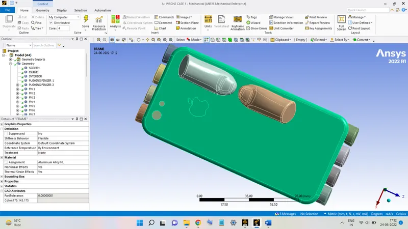
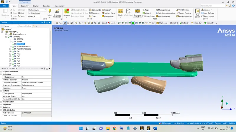
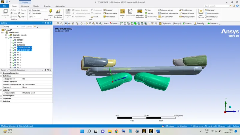
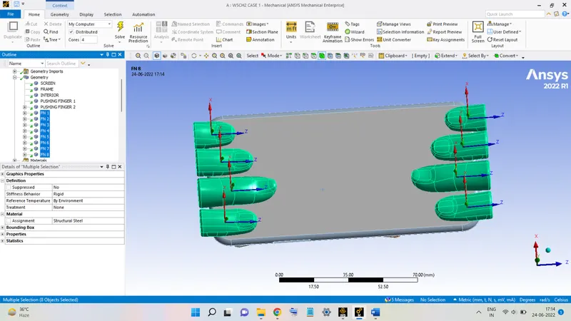
1. Expand Geometry and rename the different parts as shown in the figure below, also assign them different materials:
A) GLASS to SCREEN
B) ALUMINIUM ALLOY NL to FRAME:
C) POLYETHYLENE to INTERIOR:
D) STRUCTURAL STEEL to all the Fingers:
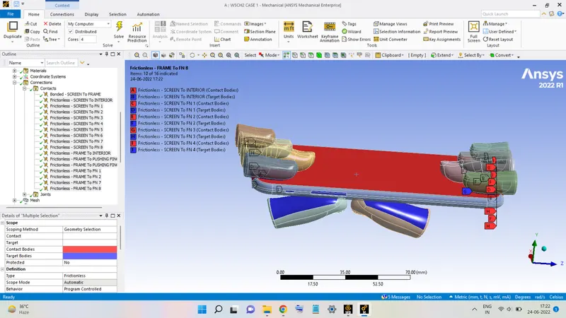
2. Go to Connections, expand Contacts and delete the contact regions with Question Mark. Then, select all the remaining contact regions and right-click select Rename Based on Definition. Select all the contacts except SCREEN To FRAME contact and change them to Frictionless, as shown below:
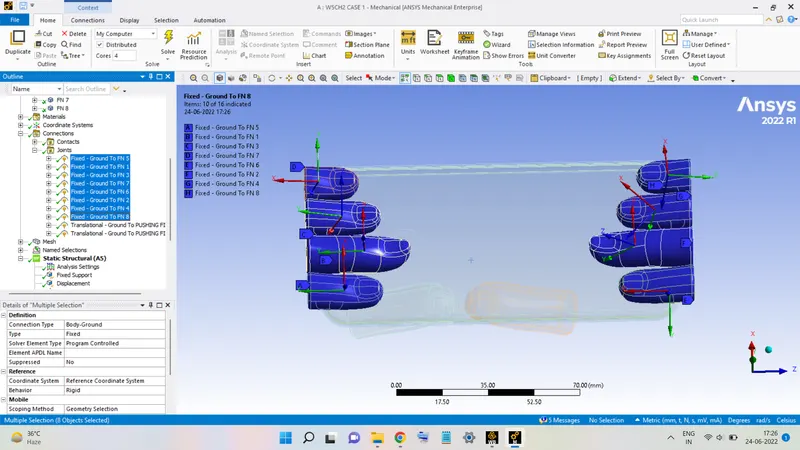
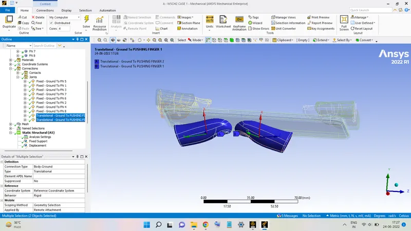
3. Assign the Fixed Joint to the top eight fingers (FN 1 - FN 8) and the Translational Joint to both the PUSHING FINGER.
4. In the Mesh section right-click and go to Insert select Sizing. select the bottom surface of the FRAME and bottom surface of the PUSHING FINGERS and hit Apply. enter the Element Size aes 4 mm and in Quality section change the Smoothing to Low. then Generate Mesh, the mesh will look like this:
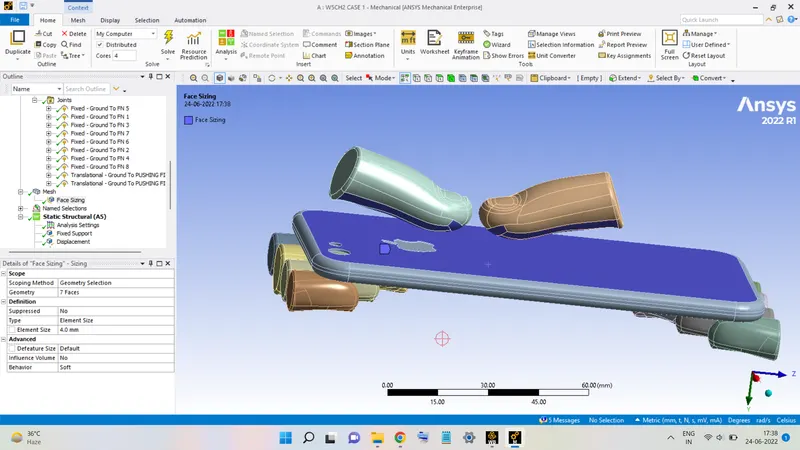
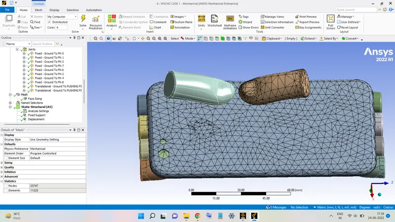
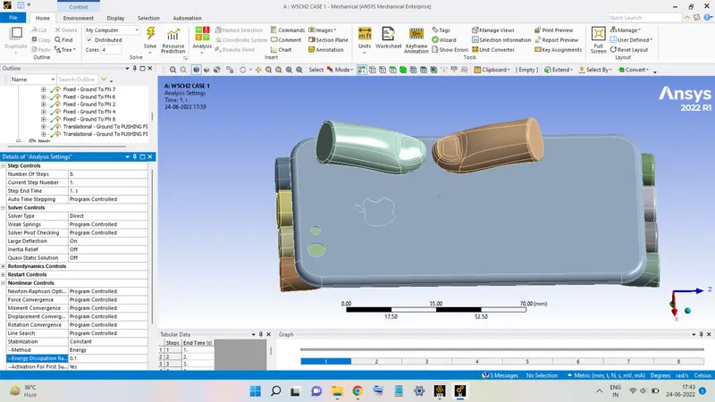
5. In analysis Settings, set the Number of Time Steps as 8. Select all the time steps and put Solver Type as Direct, Weak Springs to Program Controlled, Large Deflection to ON, and in the Nonlinear section put Stabilization to Constant and Energy Dissipation Ratio equal to 0.1.
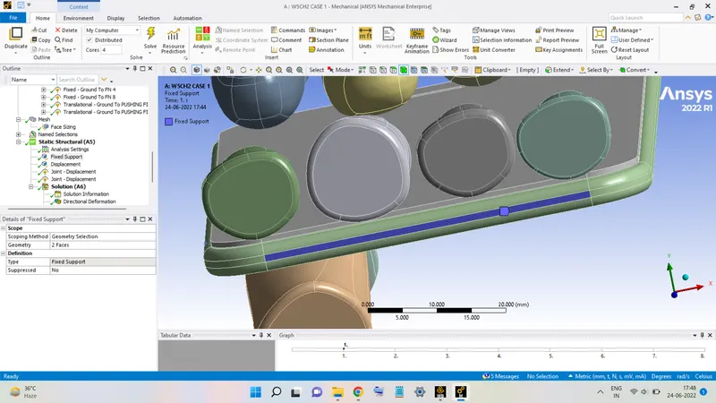
6. select the face shown below figure on the opposite sides of the INTERIOR and add them as Fixed Support.
7. Select the faces of the FRAME and assign to them the Displacement Load, as shown in the figure below:
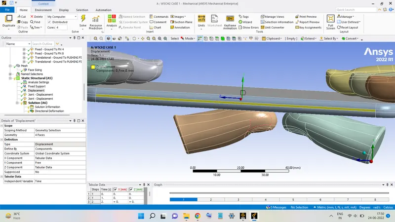
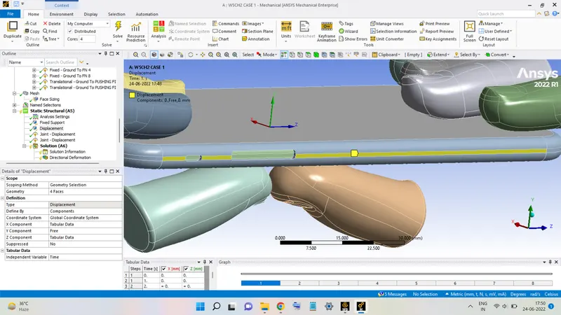
8. Right-click on Analysis Settings, go to Insert and select Joint Load. Select the Translational Joint of PUSHING FINGER 1 and select Type as Displacement, Magnitude as Tabular. the entries of the table are the displacement in X-direction up to 4 mm and the back to the original position.
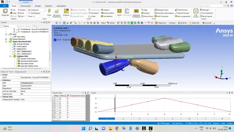
Similarly, add another Displacement Load for the joint made by PUSHING FINGER 2, as shown below:
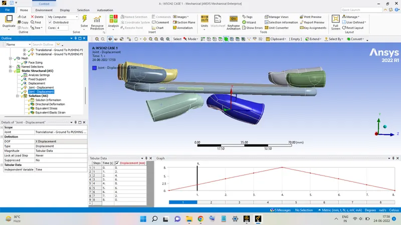
now the model is ready for the analysis, after adding useful output parameters from the analysis, click on Solve to conduct the analysis.
RESULTS:
CASE 1: Pushing Fingers present at their given positions.
Deformation along X-Axis:
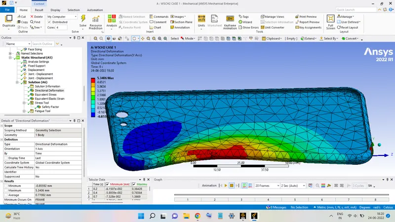
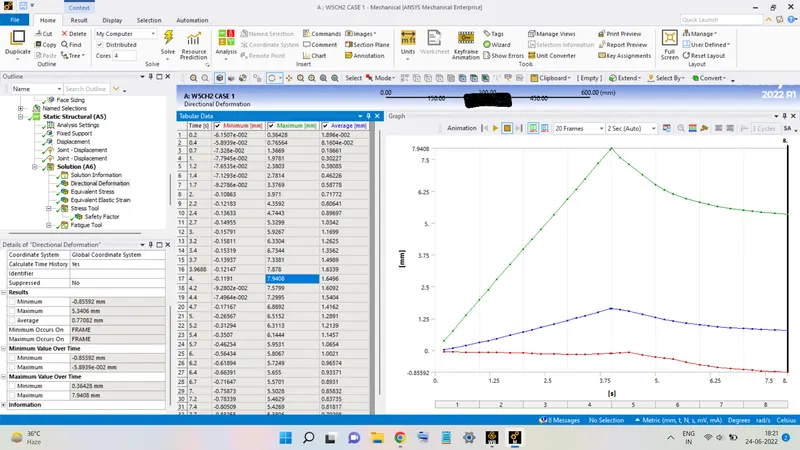
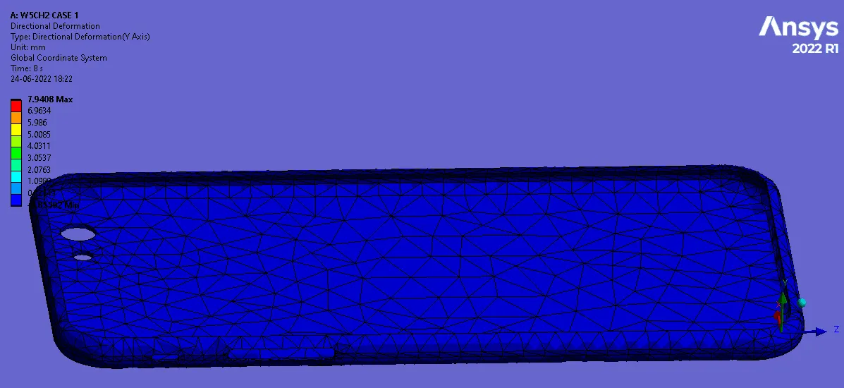
The above figures show the deformation of the FRAME during the bending operation. The FRAME is seen to be deformed most near the area of the force application. The maximum deformation is seen to be equal to 7.9408 mm.
Stress in the FRAME:
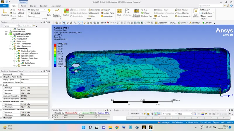
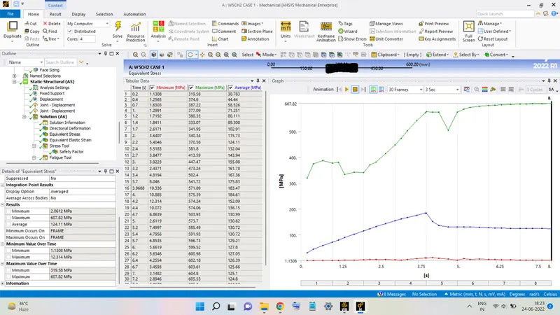
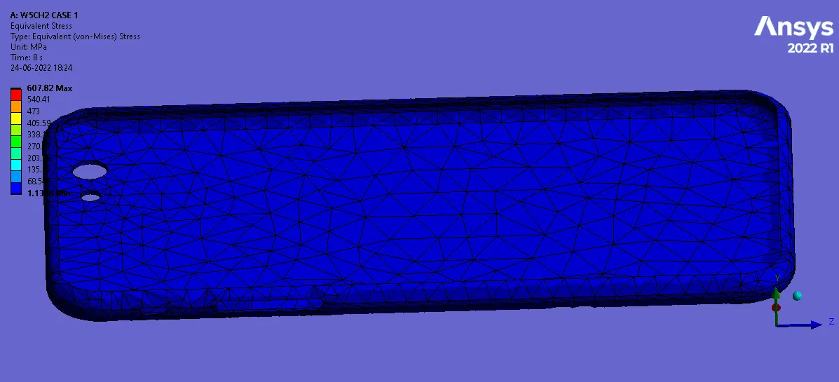
The stress developed in the FRAME during the bending operation is shown in the above figures. The maximum value is equal to 607.82 MPa.
Strain in the FRAME:
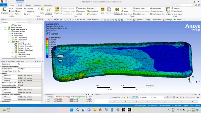
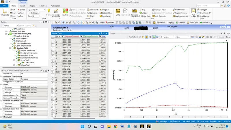
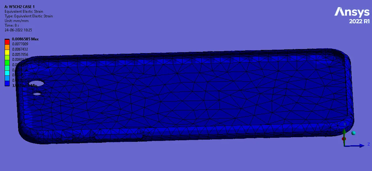
The strain developed in the FRAME during the bending operation is shown in the above figures. The maximum value is equal to 8.6585 x 10⁻³.
Factor of Safety (Stress) of the FRAME:
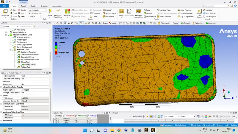
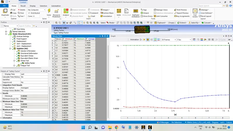
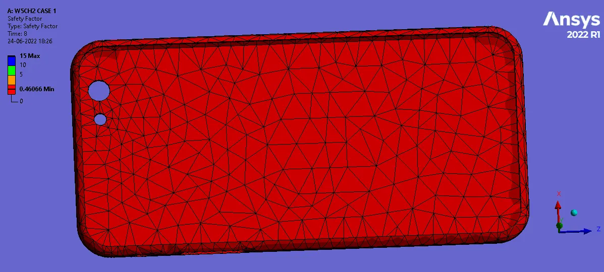
The factor of Safety result obtained from the Stress Tool is the ratio of the Actual Stress acting to the Tensile Strength of the material. The above figure shows the variation of this ratio throughout the bending operation. this ratio provides information about the regions that experience adverse loading during the operation.
The minimum value is seen to be 0.46066, this is less than Unity, therefore the FRAME is adversely loaded.
Life of the FRAME:
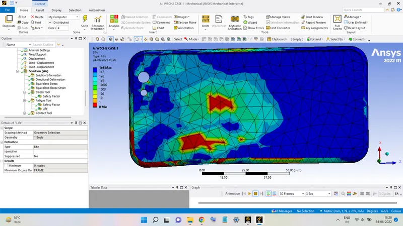
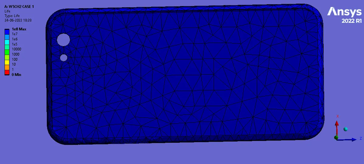
Life is the number of cycles under similar loading conditions the FRAME will withstand without any signs of failure. In the above figures, the minimum value is equal to zero signifying that the FRAME cannot sustain even a single cycle under this loading and will fail (Yield) and not be able to perform its functionality.
Factor of Safety (Fatigue) of the FRAME:
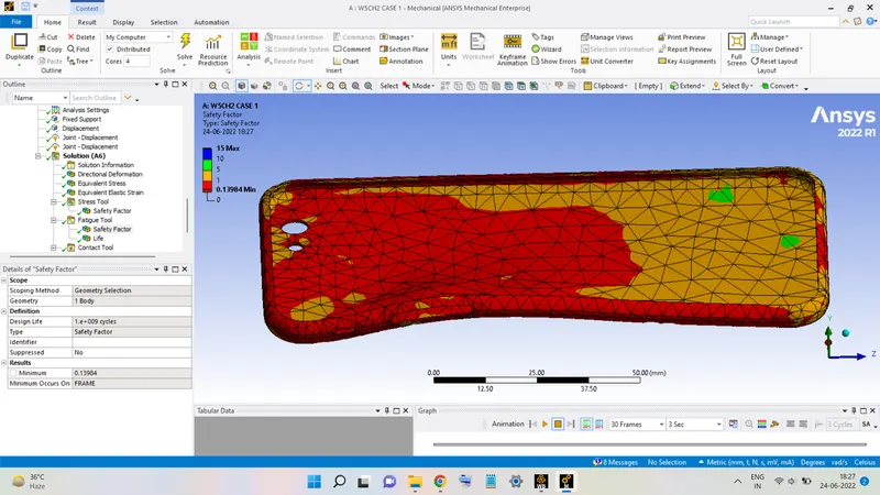
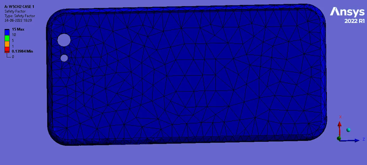
The Factor of Safety obtained from the Fatigue Tool is based on the number of load cycles. The minimum value is seen to be 0.13984. This value is less than the Unity signifying the FRAME is severely loaded.
CASE 2: Pushing Fingers present at different positions.
To change the position of the PUSHING FINGERS, select Model and then go to Part Transform.
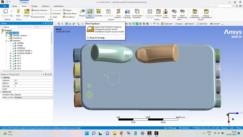
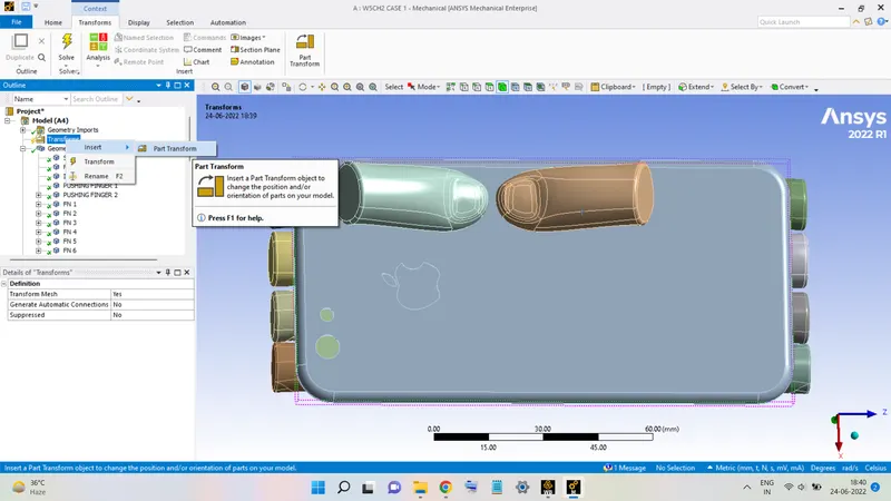
this will add a new section named Transforms in the Outline Tree. right-click on Transforms go to Insert and select Part transform.
Select both the PUSHING FINGERS and hit Apply. now, enter the translation distance along X-Axis as 22.5 mm and along Z-AXis as 10 mm. Then, right-click and select Transform.
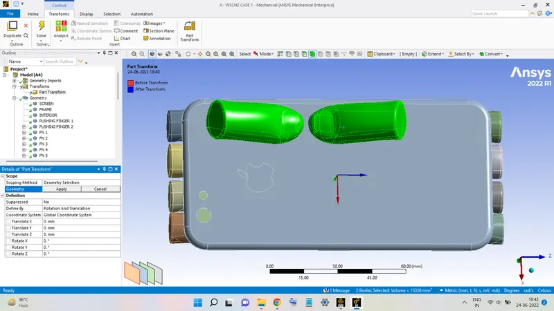
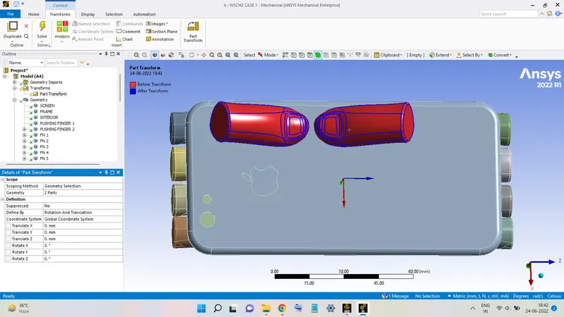
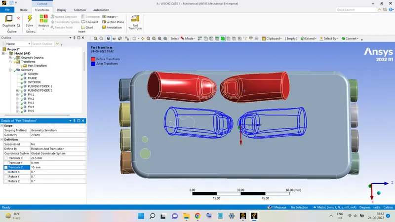
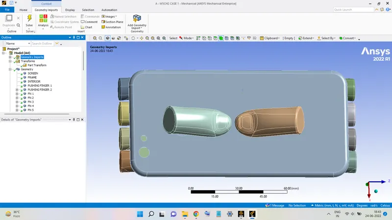
All the other settings are kept unchanged and the analysis is carried out by clicking Solve.
Deformation along X-Axis:
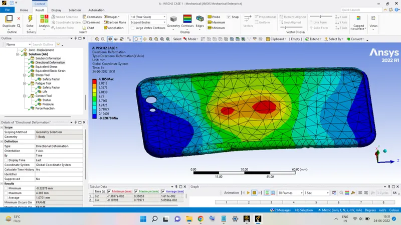
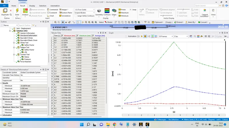
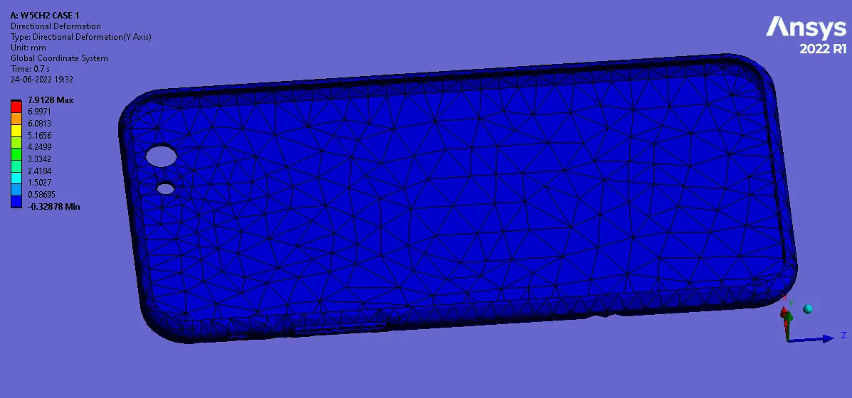
The above figures show the deformation of the FRAME during the bending operation. The FRAME is seen to be deformed most near the area of the force application. The maximum deformation is seen to be equal to 7.9128 mm.
Stress in the FRAME:
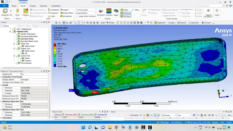
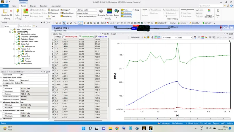
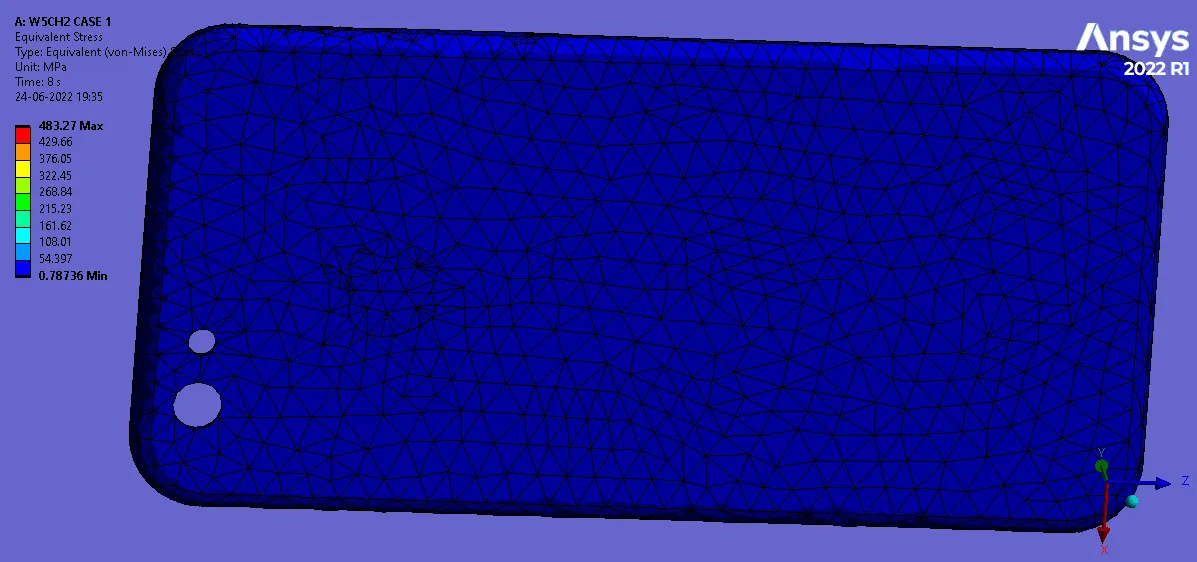
The stress developed in the FRAME during the bending operation is shown in the above figures. The maximum value is equal to 483.27 MPa.
Strain in the FRAME:
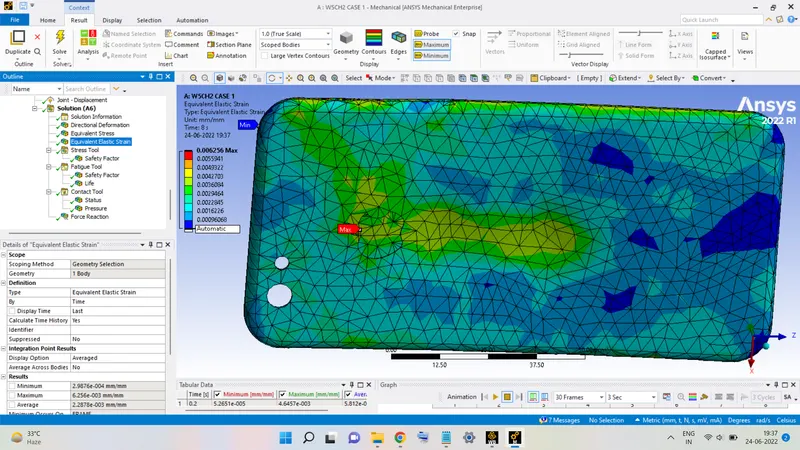
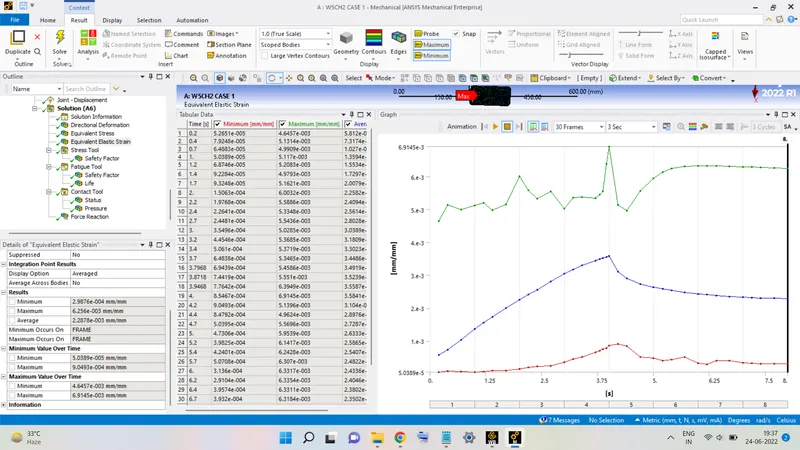
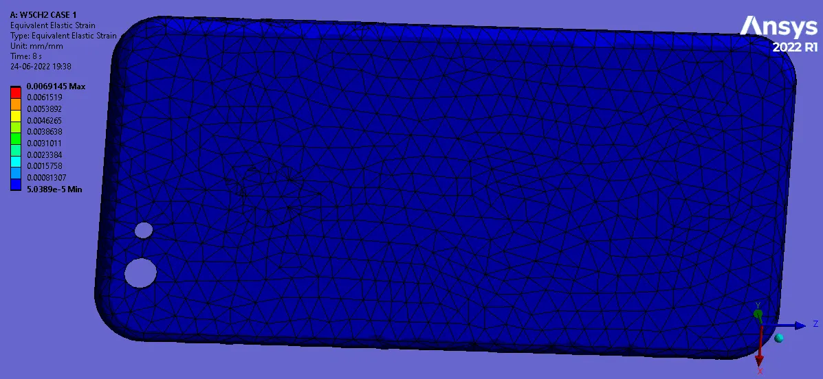
The strain developed in the FRAME during the bending operation is shown in the above figures. The maximum value is equal to 6.9145 x 10⁻³.
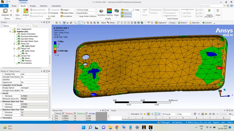
Factor of Safety (Stress) of the FRAME:
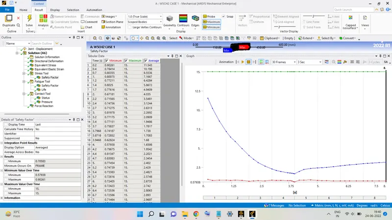
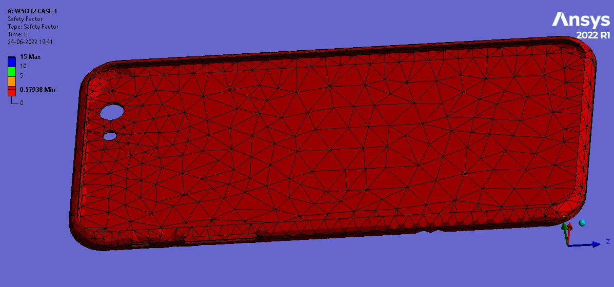
Life of the FRAME:
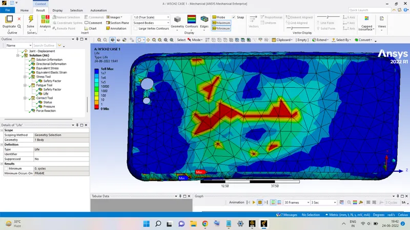
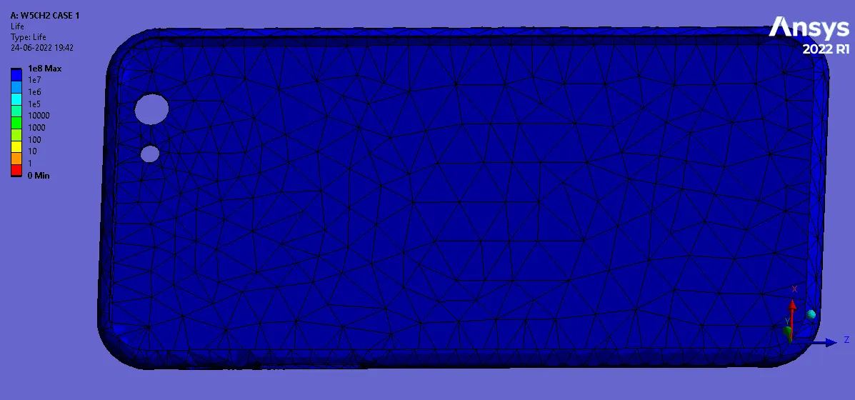
The minimum value of the number of load cycles sustained is equal to zero signifying that the FRAME cannot sustain even a single cycle under this loading and will fail (Yield) and not be able to perform its functionality.
Factor of Safety (Fatigue) of the FRAME: 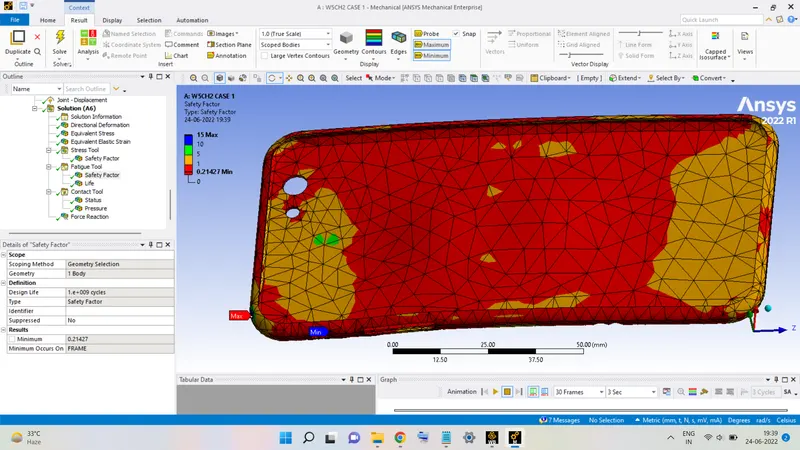
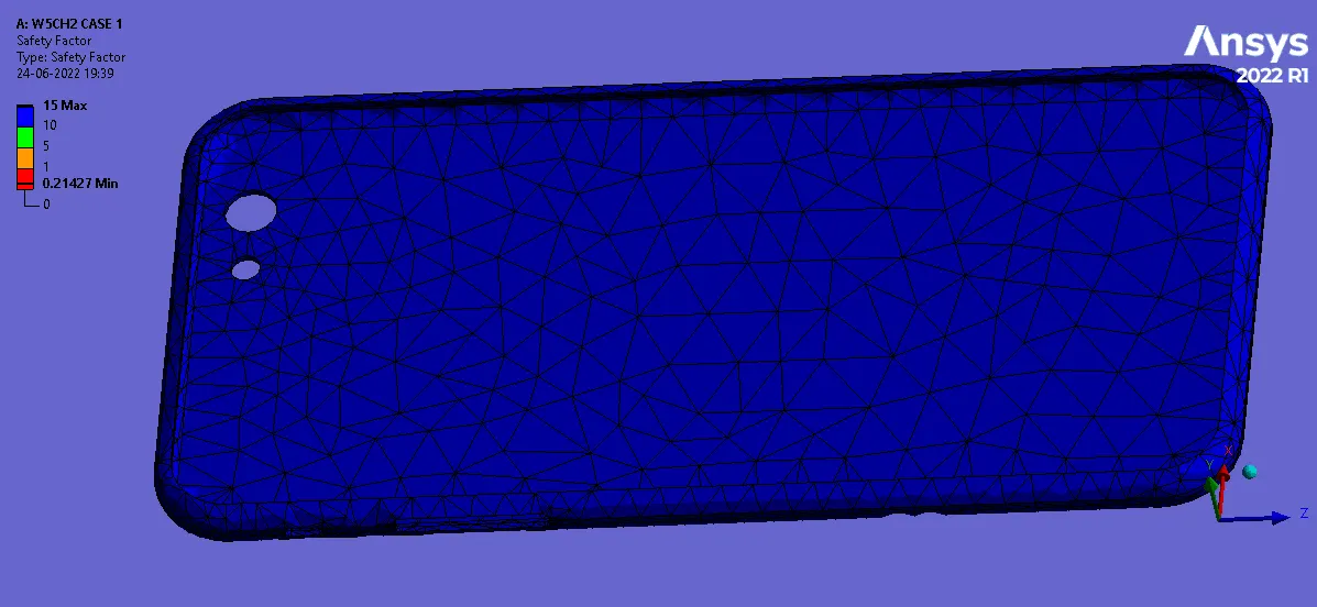
The minimum value of the Safety Factor is seen to be 0.13984. This value is less than the Unity signifying the FRAME is severely loaded.
Comparison:
The results of both the cases for the FRAME are listed below in the table below for comparison.
|
|
Max. Stress (MPa) |
Max. Strain |
Life (Number of Cycles) |
Safety Factor (Fatigue) |
|
CASE 1 |
607.82 |
8.6585 x 10⁻³ |
0 |
0.13984 |
|
CASE 2 |
483.27 |
6.9145 x 10⁻³ |
0 |
0.21427 |
After comparing the results of the two cases, shown in the above table, it can be said:
1. The maximum stress in the second case is lower than that for the first case. This is due to the fact, that in the second case the bending load is uniformly supported by the elements of the FRAME.
2. Same reason can be associated with the maximum strain developed in the second case.
3. The minimum number of cycles for both cases is ZERO. This implies that the FRAME will fail (Yielded) and lose the ability to perform the functionality.
4. Fatigue Safety Factor for the second case is slightly more than that for the first case. Since the load is more uniformly acting and supported by the FRAME therefore the Safety Factor is seen to be more in the second case.