Battery characteristics using drive cycle
Simulate generic battery model charge-discharge using UDDS data.
Answer:
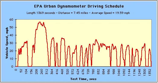
UDDS Drive cycle
Simulink model
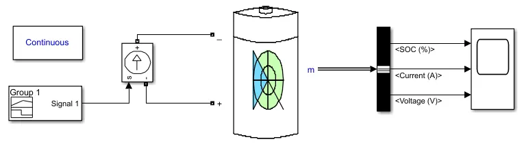
1.Signal builder:
The Signal Editor block displays create and edit interchangeable scenarios. You can also use the block to switch scenarios in and out of models.
The Signal Editor block supports MAT-files that contain one or more scalar Simulink data objects.
You can port Signal Builder block configurations to the Signal Editor block using the signal builder function.
By using this block we can give UDDS cycle current as input, for this we have to import the UDDS cycle into the signal builder block.
2.Controlled current source:
The Controlled Current Source block converts the Simulink input signal into an equivalent current source. The generated current is driven by the input signal of the block. The positive current direction is as shown by the arrow in the block icon.
You can initialize the Controlled Current Source block with a specific AC or DC current. If you want to start the simulation in steady-state, the block input must be connected to a signal starting as a sinusoidal or DC waveform corresponding to the initial values.
3.Genric battery model:
The Battery block implements a generic dynamic model that represents most popular types of rechargeable batteries.
4.Bus selector:
The Bus Selector block outputs the elements you select from the input bus. The block can output the selected elements separately or in a new virtual bus.
5.Scope:
The Scope block displays its input with respect to simulation time. The Scope block can have multiple axes (one per port); all axes have a common time range with independent y-axes. The Scope allows you to adjust the amount of time and the range of input values displayed.
6.Power GUI:
The Powergui block is necessary for the simulation of any Simulink model containing SimPowerSystems blocks. It is used to store the equivalent Simulink circuit that represents the state-space equations of the model.
RESULTS:
In this graph for battery parameters, we can see the battery SOC is becoming up & down according to the charging & discharging of the battery.
The negative current displays current coming into the battery means charging and the positive current shows the discharging of the battery.
Please find the attached excel for UDDS current profile.