Week 5 Battery characteristics using drive cycle
Model Screenshot :
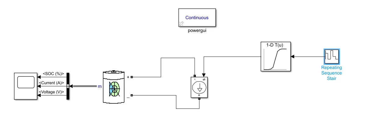
Discussion of Model and Steps : As in the challenge, we have to simulate generic battery model using UDDS data which gives us reference speed, but the problem in this is that UDDS is a drive cycle which is used for testing of vehicles (emissions, efficiency, etc....) and thus this data is speed vs time. So, either we can simulate whole vehicle in MATLAB or can take current data corresponding to UDDS data. Here, for simplicity of model second approach is being followed. Now, first this data is being imported in MATLAB as a matrix through "Import Variable" command in MATLAB. So, by selecting just the current values it will be imported as a 1370 x 1 matrix. Then, we will open simulink and use lookup table block along with repeating stair sequence block to extract this data. In lookup table block, we will select the imported variable as table data and breakpoints as even spacing data range in with space 1 and starting from 1. Thus, it will assign a natural numbers from 1 as breakpoints. Now, thus, it has become a 2D array where on giving it an input of natural number from 1 to 1370, it will output the assigned value at that breakpoint. To give it a trigger, we use a repeated stair sequence block. In that we will assign it a sequence of natural numbers from 1 to 1370 and connect it to the input of lookup table. Now, at each sample time, it will trigger a nautral number from 1 to 1370 to lookup table which will further output the corresponding assigned value. Now, the output of lookup table will be input signal to a controlled current source. Now, we will connect this to the terminals of generic battery which will then simulate the same conditions as that of UDDS. In generic battery, few changes have been done from default such as voltage and capacity so as to simulate actual vehicle battery. The output terminals of battery is connected to bus selector which is further connected to scope terminals to see the results. Also, the default Powergui block for these kind of systems is used. Thus, we will get the data. The approach where we simulate the actual vehicle is more accurate because I suppose we won't get low current in actual drivecycle case.
Discussion of Results :
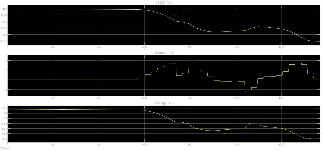
Now, in this as we can see from results current varies in continuous fashion due to interpolation performed by lookup table. When, the current is in positive quadrant it indicates it is in discharge mode, whereas when current is in negative quadrant, it indicates that current is flown back to the battery i.e. it is in a state of 'regenerative braking', thus it charges the battery. This charging comes from kinetic enegy of vehicle which would have otherwise been totally lost as heat in conventional braking. Thus, whenever current is negative, there is buildup in capacity or charging which leads to increase in SOC or voltage whereas otherwise it is decrease in SOC or voltage due to discharging. Thus, battery experiences duality of charging as well as discharging throughout the drive cycle.