Volume meshing of a rearview mirror model
AIM:
The aim of this project is to create a solid mesh for a rearview mirror model purely using tetra mesh elements post to topology cleanup. This meshed finite element model is then checked for volume mesh quality criteria and if required refined to generate more appropriate mesh elements that could pass the required quality criteria.
PROCEDURE:
1. Geometry cleanup
Prior to checking the model for geometrical errors, the hot points in the model are refined to a nodal spacing of 1mm for both the perimeter and macro side from the MESH tab.
Then a topology cleanup is performed on the model using the topo operation in the FACES block of the TOPO module.
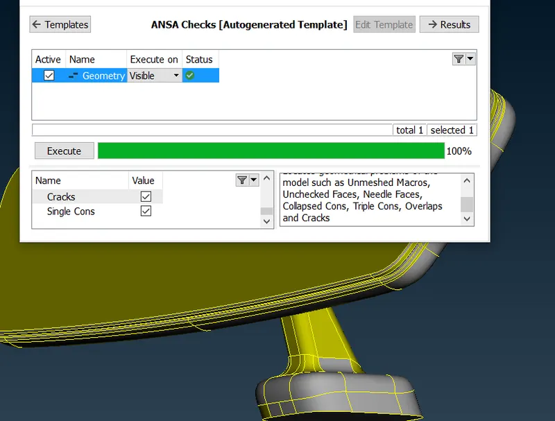
Finally, the model is checked for geometrical errors in the check manager. If any errors in triple/single cons arise, ANSA in most cases would be able to clear it using the FIX command. IF the model passes for topology cleanup the following image can be then visualized.
2. MESH PARAMETERS AND QUALITY CRITERIA
Prior to meshing the user has to define the required mesh parameters. ANSA tries to follow this input data to give a more precise mesh. However, in some cases, these mesh characteristics of the generated mesh may deviate from the user-defined parameters. Hence, to obtain a more accurate mesh we set up the quality criteria to check for those elements that fail the defined parameters.
These failing elements can then be reconstructed using ANSA's efficient mesh refinement algorithms in the MESH module.
In this project, a mesh average target length of 1 is set up in the mesh parameters tab. The type of mesh to be modeled are trias and ortho-trias. These can be switched in between in the mesh generation block.
To check for deviating elements, the quality criteria for min and max length are chosen and its values are 0.5 and 2 respectively. Similarly, the tet collapse of the to-be generated volume mesh is also selected for error checks with a value of 0.2. Hence, any mesh that doesn't fall in the above-defined shell or solid mesh criteria can then be refined using any one of ANSA's inbuilt features.
3. SHELL / SURFACE MESHING
To generate the mesh we make use of the spot mesh generation feature in the MESH module. This feature allows us to capture certain regions or surfaces of the component that are enclosed within the cons. This helps us generate both trias and ortho trias at required surfaces thereby the whole components don't necessarily have to be modeled just by one.
The reason for selecting unstructured mesh elements like trias is because they offer a more flexible pattern compared to a hexa / brick element or a quad. Moreover obtaining accuracy or smooth mesh flow pattern (structured-like) while simultaneously implementing the flexible feature of the tetra elements we can make use of the ortho tria elements. These elements having orthogonal edges can be useful to generate a smooth mesh pattern if modeled correctly. Hence these elements are a more preferable alternative to brick elements.
These ortho-trias since they give a great convergence result, they are modeled at critical places where most of the load acts and at curves and fillets since normal trias which are equilateral wouldn't be able to capture the detailed surface. Hence these trias are used at straight surfaces where the required field variable magnitude is very minuscule.
MESHING
- Every curve and fillet in the rear view mirror model are captured using ortho-trias.
- These are then reconstructed at certain areas to obtain a smooth mesh flow
- Kinks and dips should also be eliminated using reconstruction or by any other methods.
- Features that fail to follow a similar pattern can be reconstructed (as shown below). If any kinks or dips exist they will also be eliminated
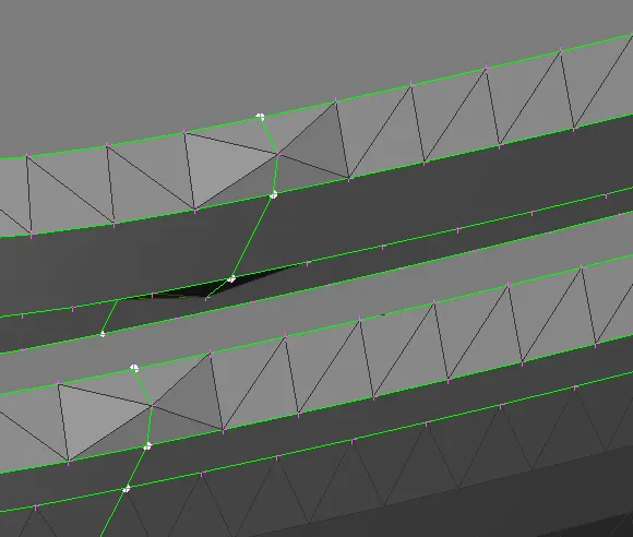
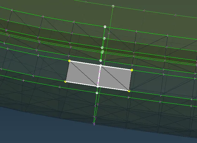
- Similarly
- The straight/flat part of the model i.e the mirror and its opposite side can be modeled using a tria element. These parts experience the least stress during loading (the hinges between the mirror and its casing are the most crucial). Since these flat surfaces experience the least so not-to compromise on the computational time, these are modeled using the tria elements.
- However, if your model is relatively small and if your workstation hardware capabilities can be overclocked so that the computational cost of such a small component isn't that significant, then even flat surfaces can be modeled using ortho-trias for more accurate results.
- The connector of the mirror model which connects the mirror to the vehicle by design (CAD) has a lot of unnecessary cons. These make the meshing of such components more tedious. Hence these cons can be removed using Macros -> Cut
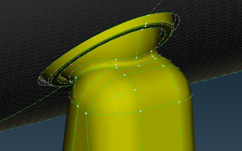
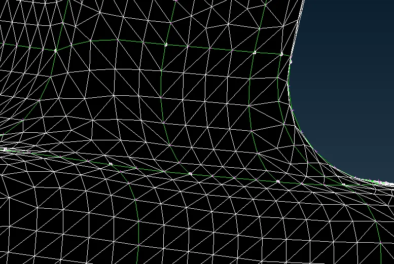
- Mesh elements that fail the max length quality check can be cleared by forming a cut using Macros -> Cut and other failing elements can be cleared by moving the grid about an origin point.
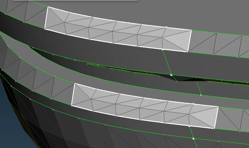
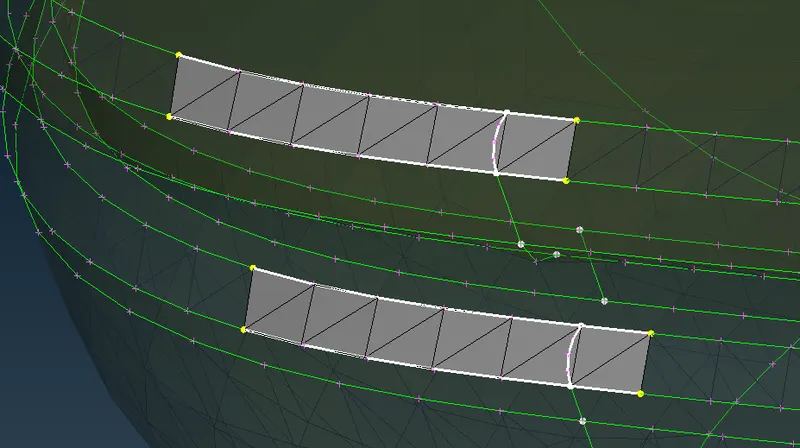
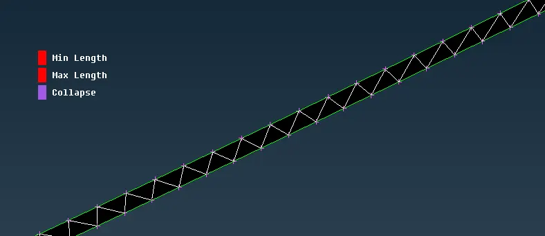
- Strip-like features that fail in aspect ratio or in this case, max and min length can be clear either by making a cut (a very tedious process). However, the most efficient way would be to increase the number of elements on one side which would pair more elements thereby eliminating the error (as shown below)
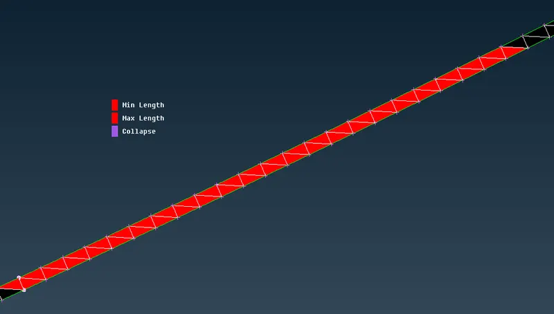
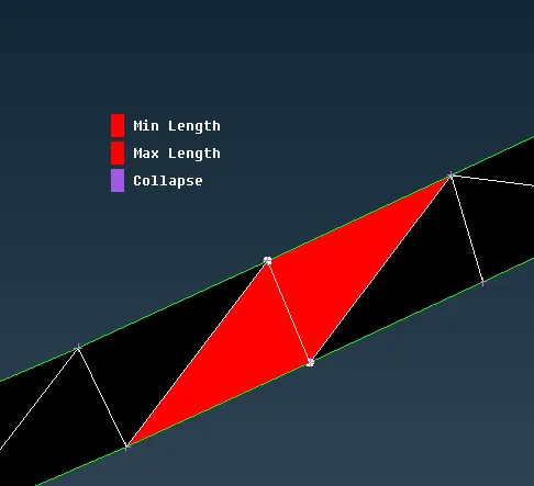
- Features that still fail for max/min length due to hot points that cant be removed, can be joined using Elements -> Join
- The circular strip near the connector of the rearview mirror fails in aspect ratio or max/min length for each element. Increasing the number of the element or any cut operation could not rectify it since the width of the strip would also keep an undesirable aspect ratio. Hence for such cases, the thin strip projection is removed using Macros -> cut and then re-meshed (the error and its result are shown below)
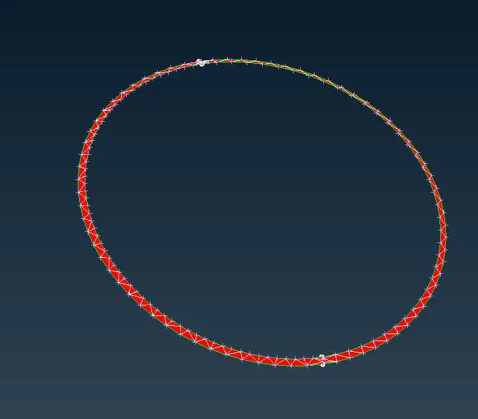
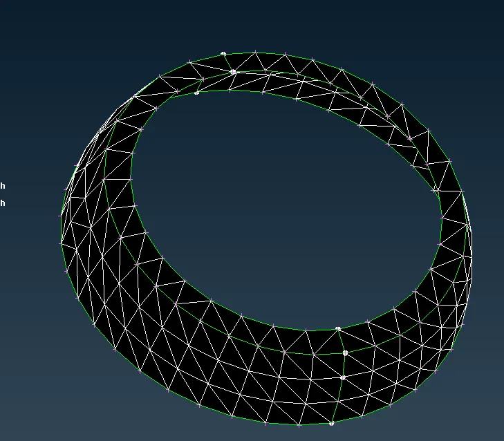
Finally, each element in the surface mesh passes for the desired quality criteria.
Now we can construct a volume mesh within the volume of the model.
SOLID MESHING
To create a solid mesh using the ANSA inbuilt unstructured mesh command, a volume has to be defined prior to mesh generation. The basic process by which a mesh is generated across the volume is by mapping the surface meshed elements on either side of the component. Hence due to this reason, a complex and intricate component like our model (or similar) would fail since the model comprises intersections and sub-components.
Hence performing a solid meshing using any mesh algorithm with the object as a whole would result in an error since the volume is not defined as an enclosed one. Due to this ANSA might mistakenly consider a surface within the volume to be a mid-surfaced model and hence fail to generate a volume mesh.
To overcome this, the model has to be separated into individual volumes so that our pre-processor can distinguish each component within the model.
To discretize each surface volume component we can make use of the AND, OR,!NOT command while the selection parameters is tuned for PID region (as shown below)
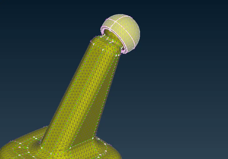
This would separate our model into 4 components as shown below,
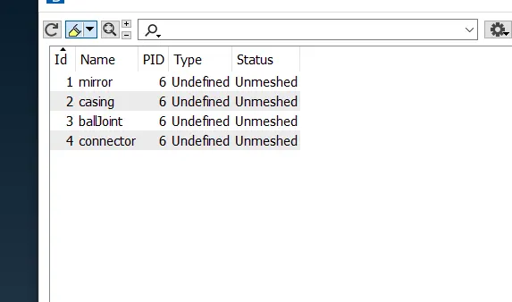
Each of these sub-components can then be meshed (right-click-> remesh -> select algo) using tetra elements using any one of the ANSA inbuilt algorithms - Tetra Rapid or Tetra FEM.
This would result in each of the components being meshed and can be visualized as shown below.
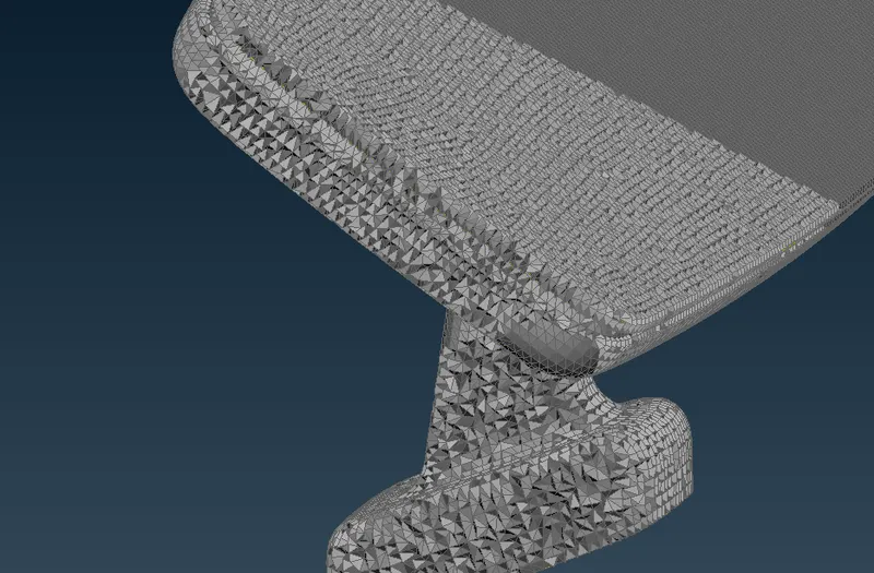
Finally as done for surface meshing, the solid mesh elements should be check for quality errors. The main mesh quality criteria for a tetra mesh element is tet collapse (in this case, a value of 0.2)
The default value that most solvers check for is 0.75. However, a value of 0.2 is respectable in most cases depending upon the model and its application.
If any tet collapse failure occurs it can be cleared using the Fix quality operation or by moving the grid. However, in my cases, no element failed for a tet collapse of value 0.2.
CONCLUSION
Finally, the solid mesh inside the volume can be visualized by splitting open the component using the hide entities command.
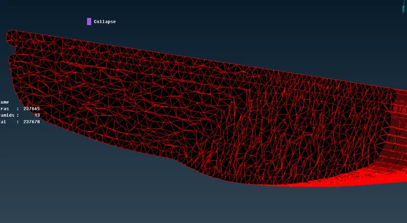
We can see that the first layer of the volume mesh is consistent with the surface mesh, however, as it progresses through the volume center the pattern changes due to tetra mapping between both the opposite faces, this can be modified by changing the growth ratio of the solid mesh parameter
Learning outcomes
Gained knowledge on,
- creating a surface mesh of either tria or otho tria elements using spot mesh
- more ways to refine the surface mesh
- creating volume mesh using tetra elements and checking for quality using tet collapse
- possible errors (volume intersection) during volume mesh of intricate geometries
- Eradicate tet collapse errors