Tetra Meshing of Rear View Mirror
AIM- To mesh the given model using tetra(solid) elements.
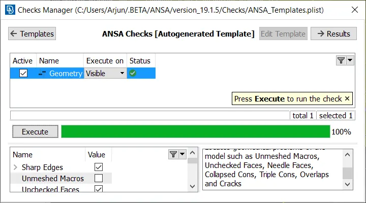
Step1- After importing the model into ANSA, we first check for the geometry and CAD quality. Geometry issues such as Triple CON formation and Needle faces are found to be present. Some are auto fixed (Right click on the error --> Fix) ,other CONS have to individually released and then joined to the appropriate surface by using 'TOPO'. Once all issues have been removed, the CAD is clean and no geometry errors are present.
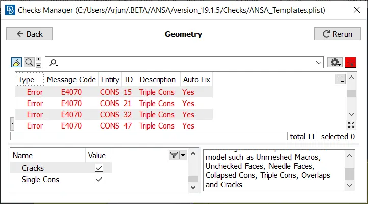
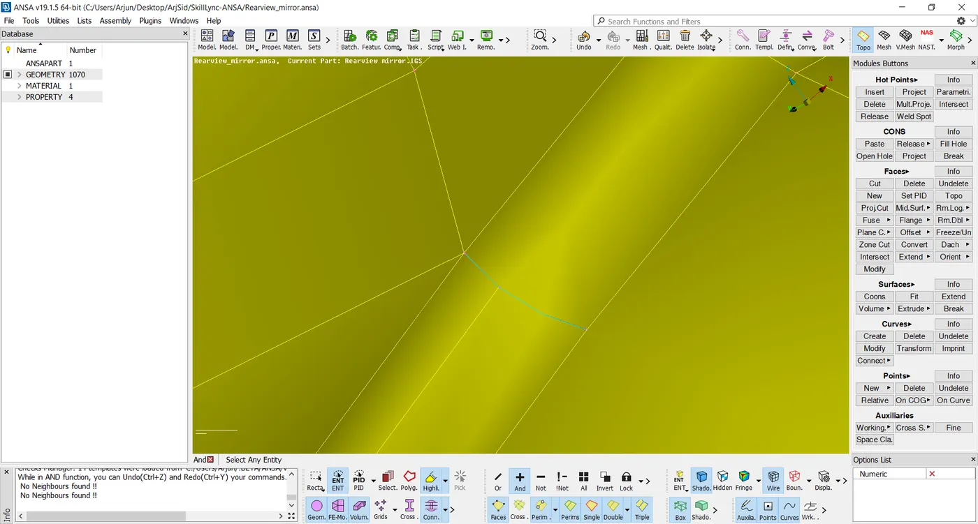
Triple CON
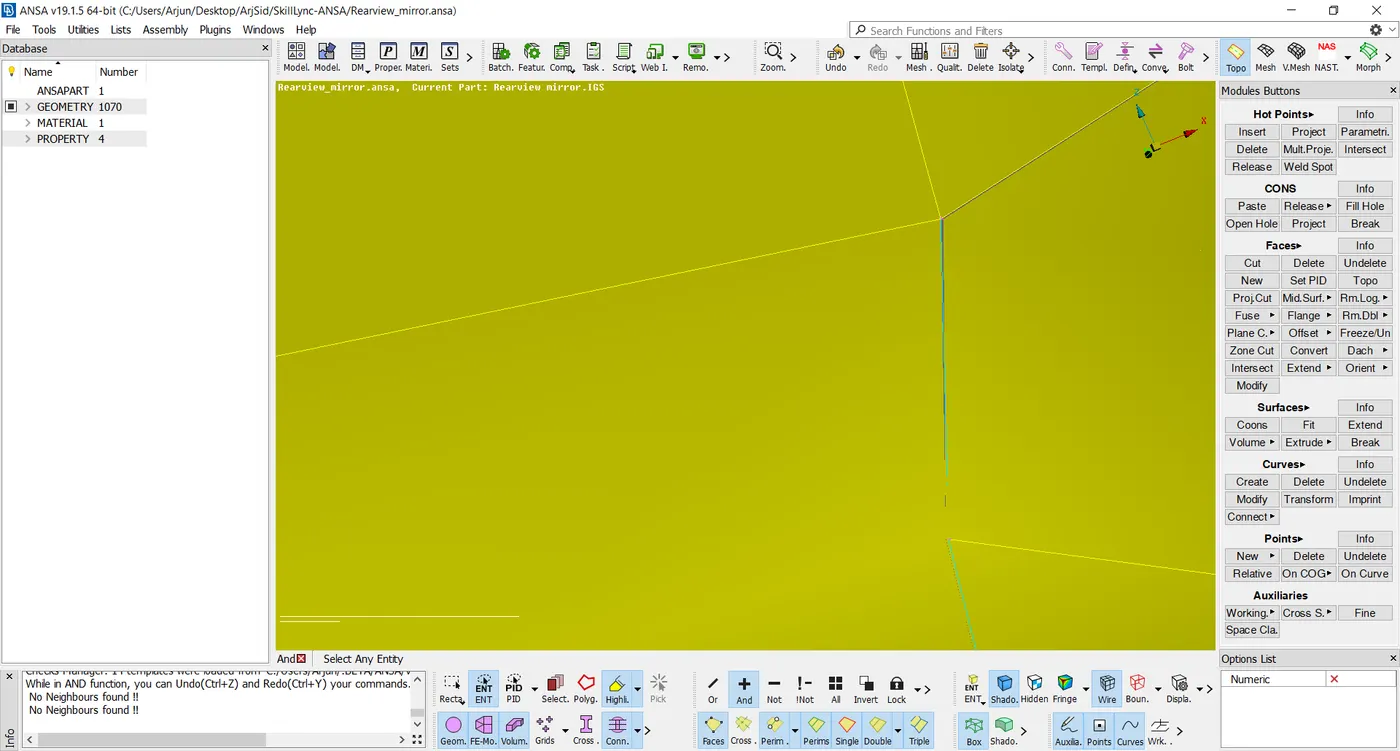
Needle Face
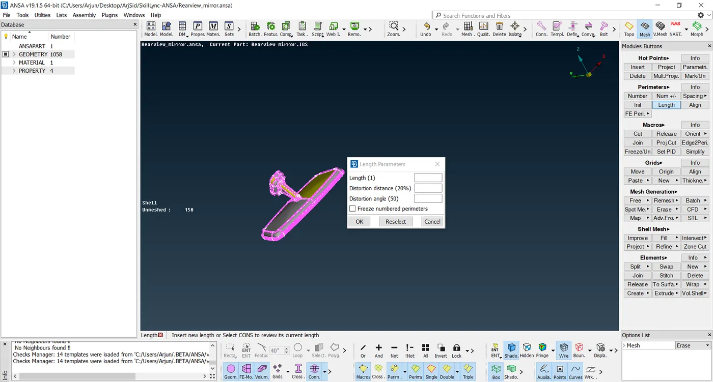
Step2- In Mesh mode, we increase the length of Perimeter elements to 1mm. This is done to refine the model, so that the features are represented accurately, and we can further check to see if there are any geometry issues which need to be rectified.
Step3- We can then move on to meshing the surface of the mirror. In order to create a good mesh,which accurately represents the CAD geometry,we do the meshing region by region. For the curved regions or circular geometry regions, we use ortho tria elements. This is because ortho tria elements converge better in these regions and accurately represent the geometry.In the flat areas of the geometry we use tria elements. Ortho elements are not needed in these areas, the geometry converges by using tria elements itself. Too many ortho elements is not desirable as the computation time required for ortho tria elements is greater.
Before meshing, we enter the mesh criteria and the desired quality criteria for the shell elements.
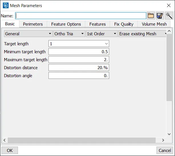
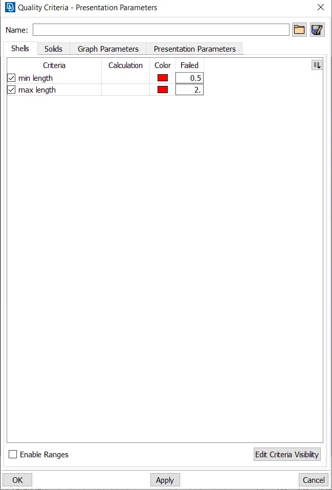
Spot mesh command is used to mesh the different areas.Ortho tria elements are used in curved edges as shown. Tria elements are used in the remaining flat regions. If there are any elements present which do not satisfy the entered quality criteria, we reconstruct the mesh selecting these elements and the adjoining elements. Macro cuts can be made and removed in order to mesh the component too.
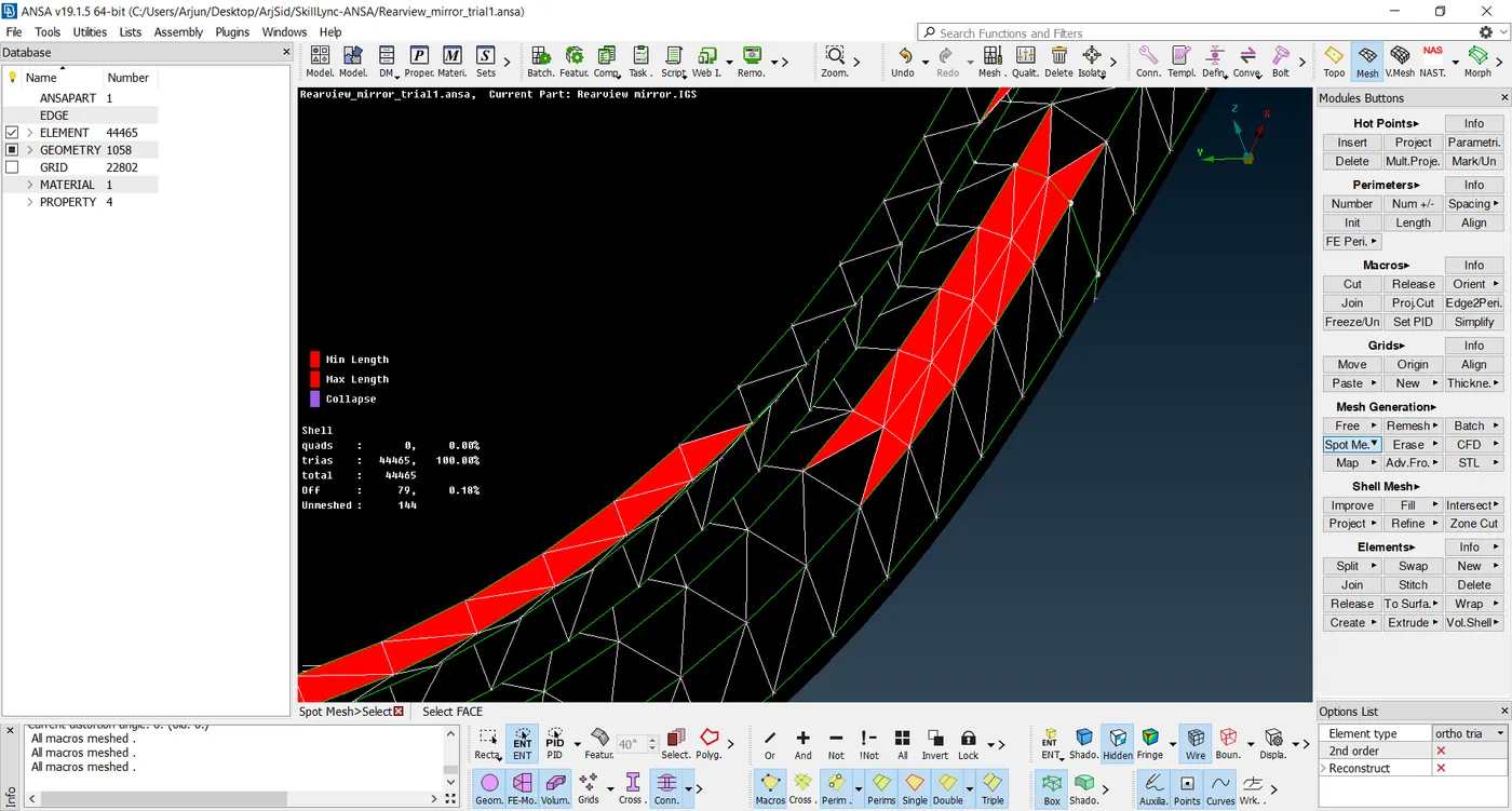
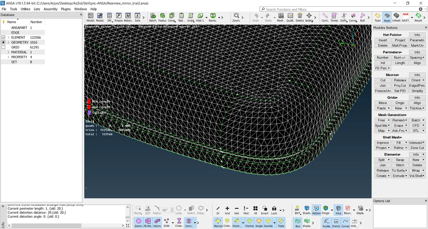
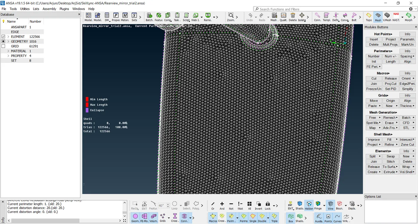
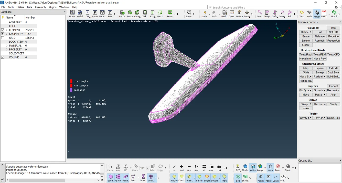
Surface Meshed model is as shown-
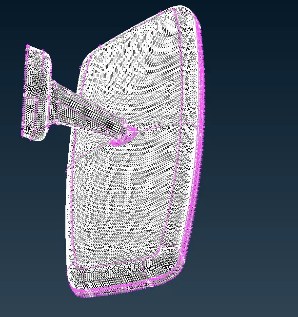
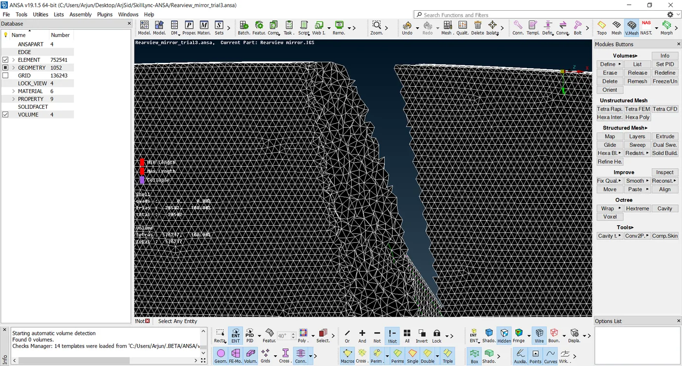
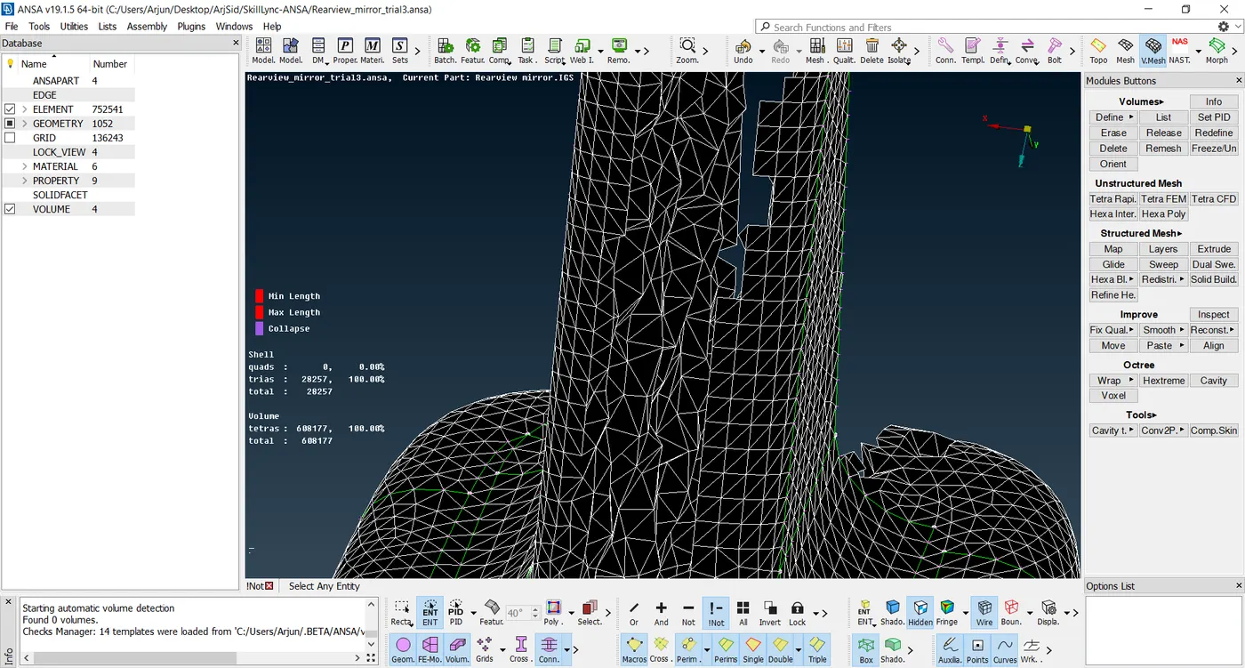
Step4- After the surface mesh, we have to generate volume (tetra) mesh. For this we first have to define the component as a closed volume. It can be done manually by selecting the component or can be auto detected. Each volume created is then remeshed by using either Tetra FEM or Tetra Rapid method. This created the volume tetra mesh. 'Collapse' quality criteria for solid elements is entered as 0.2. If any elements are failing for this criteria, it is corrected by using 'Fix quality' or using the 'MV Free' command. It is ensured that in doing so, none of the elements are protruding out and creating kinks or surface non conformities. The surface has to be uniform and free from any raised edges.
The volume meshed model is as follows-