Week 4 -Wire Bending Challenge
AIM :
To Performing a Simulation for bending of an wire with different materials, All should be done in ANSYS.
OBJECTIVES :
Adding & Assigning an appropriate materials as per requirements.
Applying a connections between the contact surface.
Discritization of a given components.
Applying a Boundary Conditions.
Calculate the Equivalent Stress and Equivalent Strain for Work piece.
PROCEDURE FOR ACQUIRING THE OBJECTIVES :
I) CAD Model :
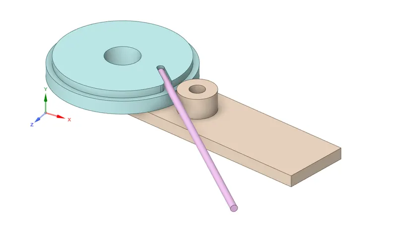
A Cad Model is given from design team. We have to import that model file into Geometry Selection option, inorder to cross check the model on whether given geometry has perfect or not. A Model is looks like perfect and its consists of Wire, Fixed Wheel and Lever.
II) Material Card Adding and Assigning :
In this Cases, we can use four different materials which are Structural Steel, Copper Alloy, Magnesium Alloy & Aluminium Alloy Non Linear material.
We can Use Structural Steel as a material for Fixed Wheel & Lever.
For Wire, we can use rest of the material according to case requirement.
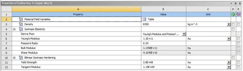
Copper Alloy Non Linear Material :
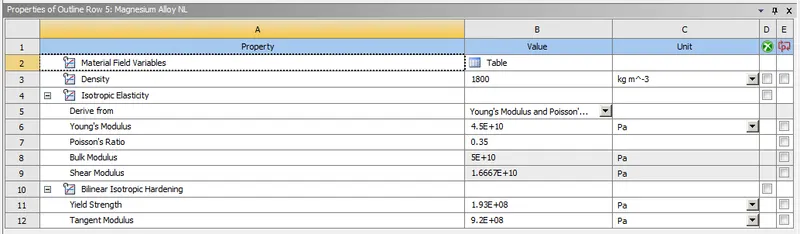
Magnesium Alloy Non Linear Material :
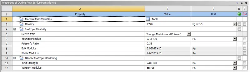
Aluminium Alloy Non Linear Material :
III) Connections :
Frictional Contact between Wire and Lever :
Select the wire outer surface as a Contact Body and Select the lever contact face as a Target Body.
Keep Contact type is Frictional and coefficient of friction is 0.2.
Keep "Augmented Lagrange" for Formulation type .
Enable "Factor" for Normal Stiffness and the corresponding value is 0.1.
Keep "Each Iteration" for Update Stiffness.
Keep "Add Offset, Ramped Effects" for Interface Treatment.
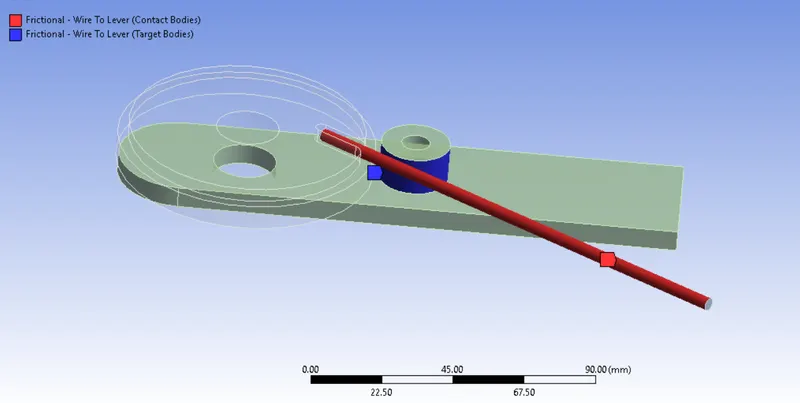
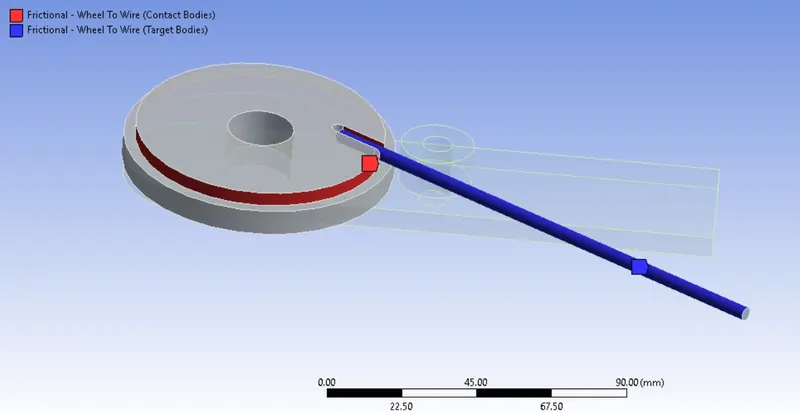
Frictional Contact between Wheel and Wire :
Select the Wheel Contact face as a Contact body and Select the wire outer face as a target body.
Similarly, Keep all those things remains same like as we did in previous one.
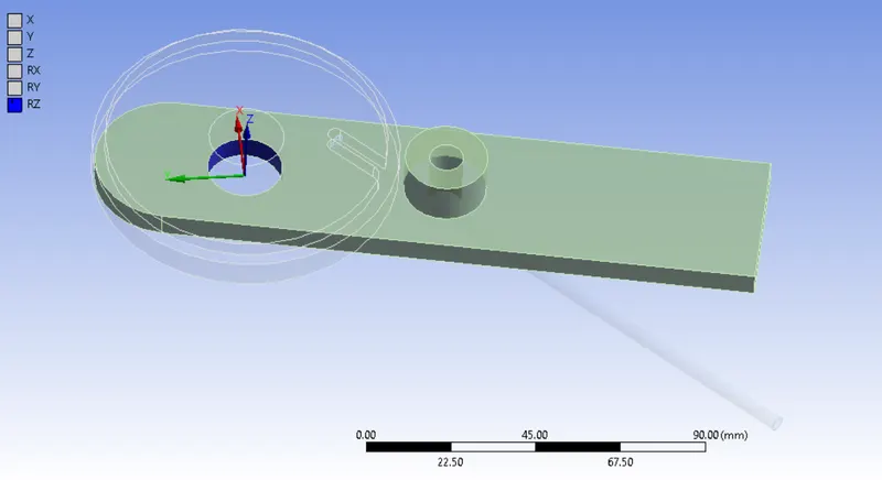
Revolute Joint for Lever :
Create a New Joints, followingly select the inner face of the Lever and then make some changes like "Body to Ground " instead of "Body to Body" as a connection Type.
Choose "Revolute" as a type of joint, it will automatically constraint in all possible motions except revolution about an Z axis.
IV) Meshing :
To divide the entire model into infinitesimal control volume, that frame work is called Meshing. This process is called Discritization. This FEM is widely used for solving partial differential equation in different physical field such as Structural problem, Heat transfer problem, Fluid flow problem, Electro magnetic Analysis & Acoustics Analysis.
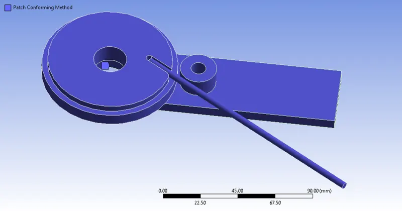
Patch Conforming Method :
Select the all bodies, then we gonna choose Tetrahedral method, it will generate the voulmetric elements based on the Patch Conforming Method algorithms.
Face Sizing between Wire face and Lever contact surface :
Select the Wire outer face & Lever contact surface and then refining the elements with size of 2.2 mm.
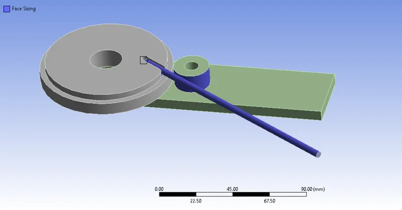
Meshing by using Sphere of influencing :
Create a new coordinate system between wire and fillet region.
Change into Sphere of influence as a type of selection. Provide the radius of sphere is 7 mm and size of the element is 0.8 mm.
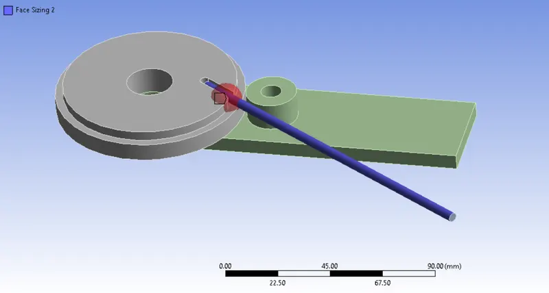
Number of Nodes = 8026
Number of Elements = 4008
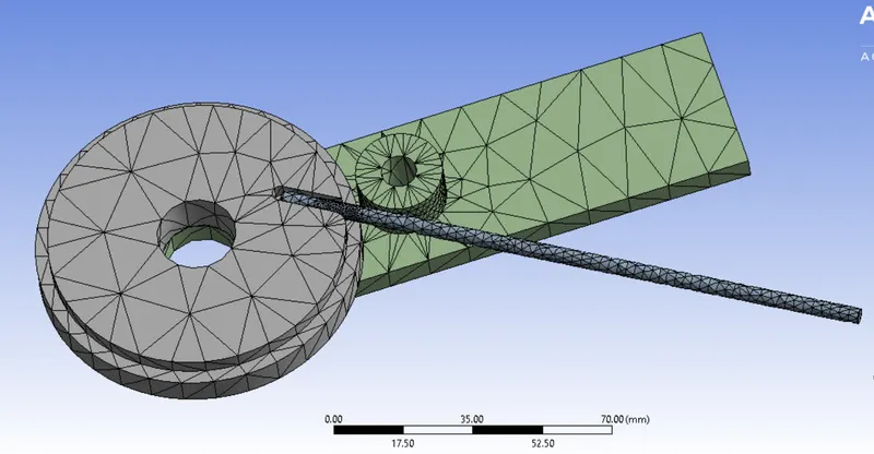
All Bodies are meshed with Tetrahedral Volumetric Meshing.
Once done the meshing, it will looks like as shown in the below image.
Analysis Settings :
In this case, we have to run the simulation by 8 steps.
Step 1 :
Keep "ON" for Auto Time Stepping.
Change into "Time" for Define By option.
Initial Time Step is 0.1 sec.
Minimum Time Step is 0.01 sec.
Maximum Time Step is 0.2 sec.
Change into "Direct" for Solver Type.
Keep "ON" for Large Deformation.
Change into Yes for all parameters which are comes under the Output Controls.
Steps 2 to 8 :
Keep "ON" for Auto Time Stepping.
Change into "Time" for Define By option.
Carry Over Time Step is "ON"
Minimum Time Step is 0.01
Maximum TimeStep is 1.
Change into "Direct" for Solver Type.
Keep "ON" for Large Deformation.
Boundary Conditions :
Displacement on the Wire Surface :
Select the Outer face and followingly provide the displacement value as Zero on along the Y direction. Keep free for both X & Z direction.
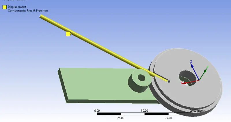
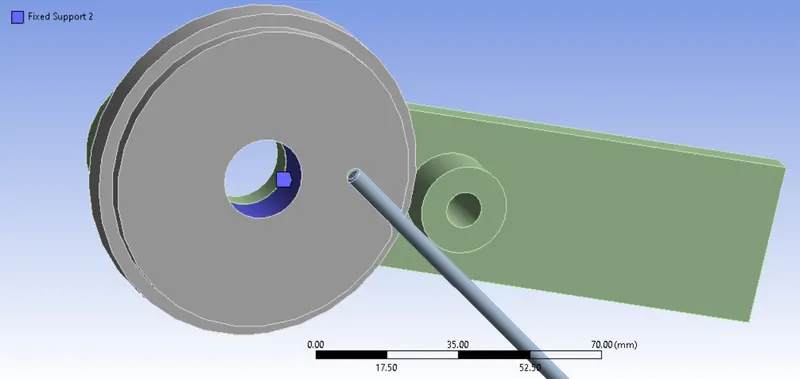
Fixed Support on the wheel inner face :
Inorder to wheel has to be act as rigid body while simulation, We have to select the inner face of the wheel and followingly create a fixed support.
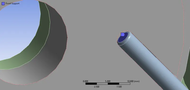
Fixed Support on the inner circulare Face :
Inorder to resist the wire sliping from the slot, we have to select the face and then make into fixed end.
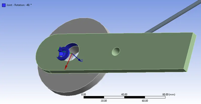
Rotational Joint for Lever :
Select the Inner face of the lever and followingly provide the angular displacement from 0 to 195 degree with the interval of 8 Steps.
RESULTS :
Equivalent Stress :
Case 1 :
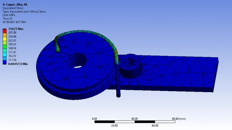
Case 2 :
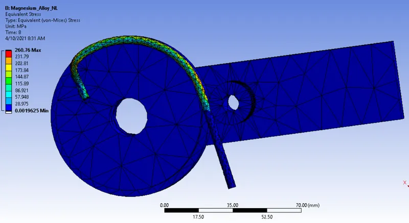
Case 3 :
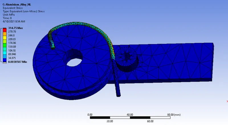
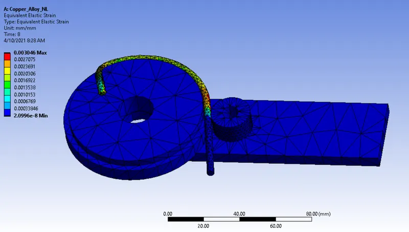
Equivalent Strain :
Case 1 :
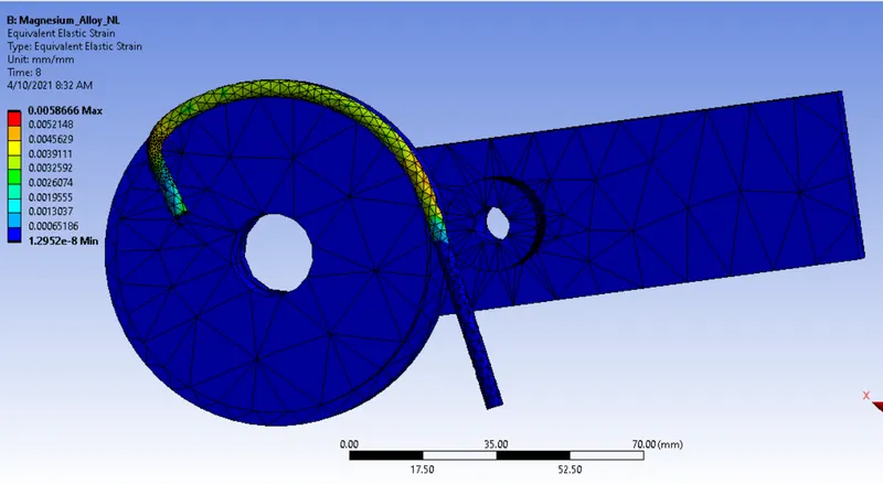
Case 2 :
Case 3 :
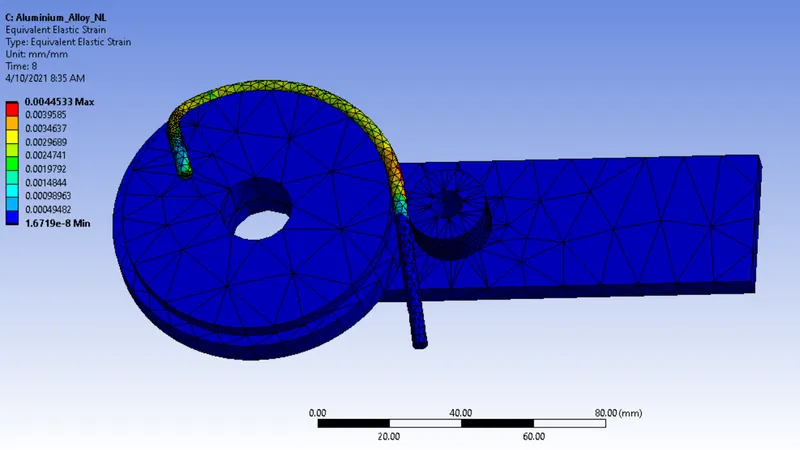
Equivalent Strain for Work piece :
Case 1 :
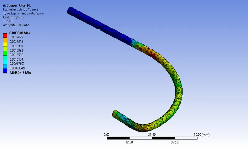
Case 2 :
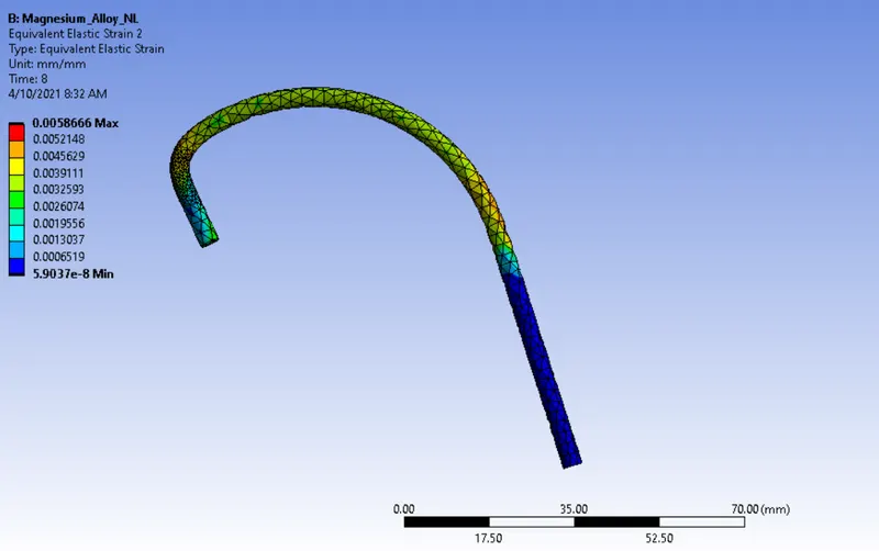
Case 3 :

CONCLUSION :
| Materials | Equivalent Stress in Mpa | Equivalent Strain | Equivalent Strain for Work piece alone |
| Copper Alloy NL | 334.21 | 0.003046 | 0.003046 |
| Magnesium Alloy NL | 260.76 | 0.0058666 | 0.0058666 |
| Aluminium Alloy NL | 314.75 | 0.0044533 | 0.0044533 |
Based on the simulation results, a Coppey Alloy Non linear material Equivalent Stress is higher as compared to remaining two materials. If the equivalent stress value is higher, by results we have to apply a more load to change the shape of the work piece.
If the Internal Resistance is more, by results Equivalent Strain is pretty low as compared to remaining two materials.