Week 4 -Wire Bending Challenge
Wiring Bending Static Simulation in Ansys
Objective
Simulate the wire bending simulation, perform 3 cases of the wire bending by changing the material and compare the results.
Briefing
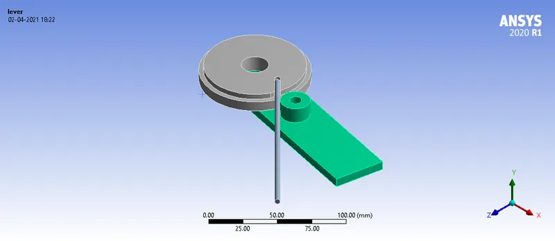
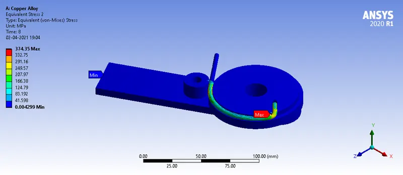
The model consists of three parts: Wheel, lever, and wire
The wheel is fixed and the lever is moved to bend the wire.
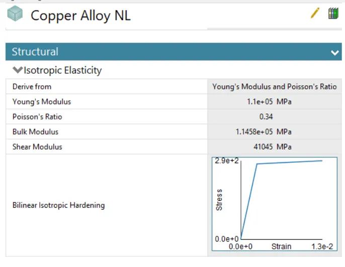
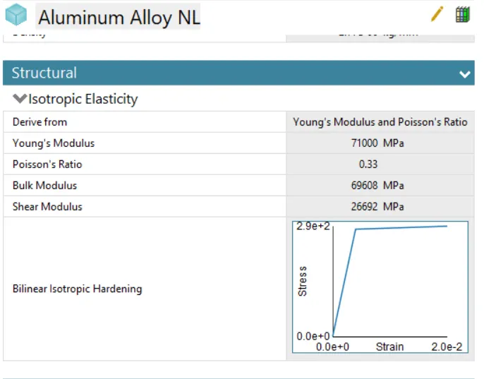
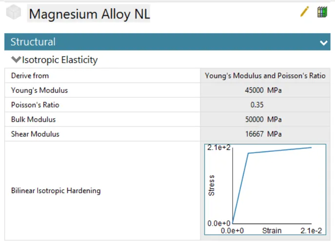
Three different materials are used for the wire which are - Copper Alloy NL, Aluminum Alloy NL, and Magnesium Alloy NL.
Procedure and Setup
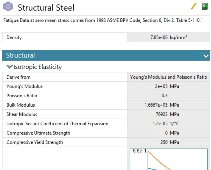
- Materials - Copper Alloy NL, Aluminum Alloy NL, and Magnesium Alloy NL are used for the wire and other parts are given structural steel materials.
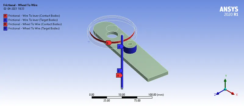
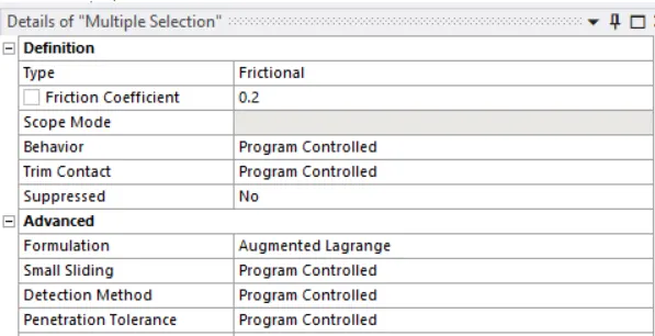
Contact Definitions: Frictional contact is defined between the wire, lever, and wheel contact surfaces.
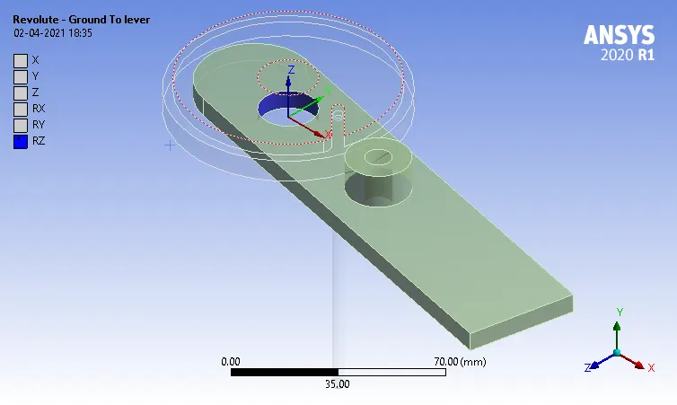
Joint Definition: A Revolute joint is defined for the lever to rotate the lever while the wheel remains fixed.
Meshing:
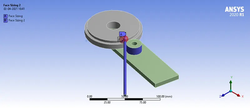
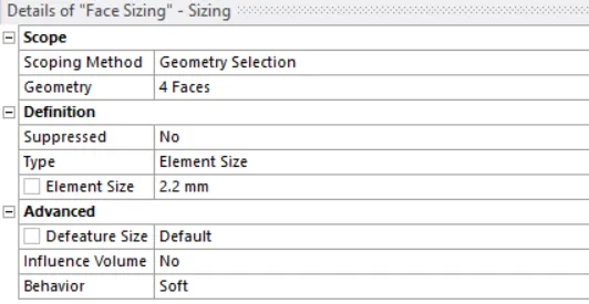
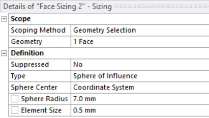
Face Sizing and Sphere of Influence are used to refine surfaces where large deformation and contact happens.
Boundary Conditions
Wheel is fixed
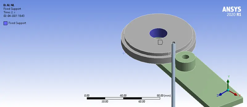
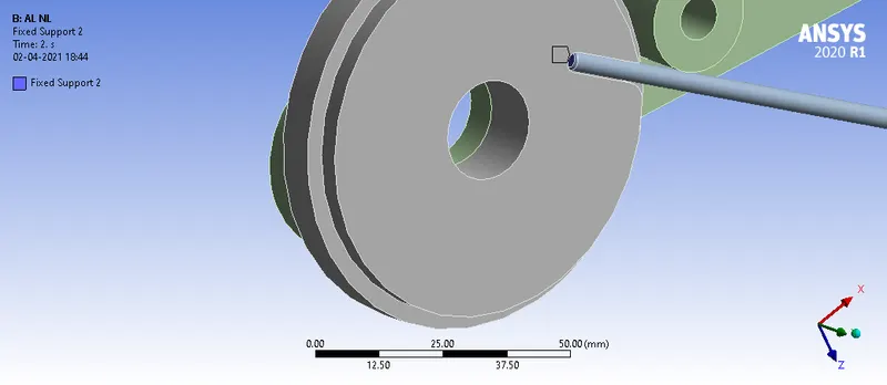
The end of the wire is fixed such that it will not slip out when the wire is bend.
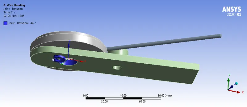
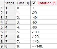
The lever with the revolute joint is given rotation movement in steps
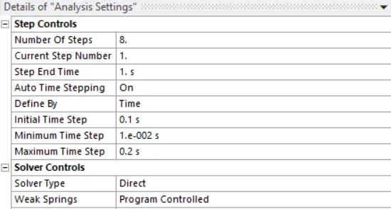
Analysis Settings: A direct solver method is used to simulate this model for 8 load steps.
Results and Case Study
| Parameters / Materials | Copper Alloy NL | Aluminum Alloy NL | Magnesium Alloy NL |
| Max Equivalent stress in Wire (Mpa) | 667.77 | 456.46 | 503.98 |
| Max Equivalent strain in Wire | 6.1242e-003 | 6.4753e-003 | 1.1288e-002 |
| Yield Stress (Mpa) | 280 | 280 | 193 |
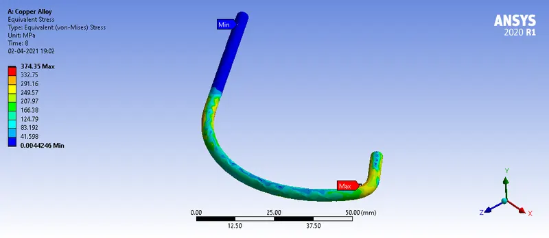
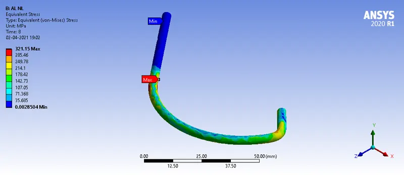
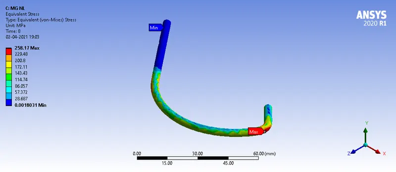
- We can see that all the materials have crossed the yield stress limits and have gone into the plastic region.
- Compared to the Copper Alloy NL and Aluminum Aluminum NL, Magnesium Alloy has undergone maximum strain for the same rotation of the lever.