Week 4 -Wire Bending Challenge
AIM: - PERFORM THE STRUCTURAL ANALYSIS OF A WIRE BENDING OPERATION USING WIRE DIFFERENT WIRE MATERIALS AND COMPARE THE EQUIVALENT STRESS AND EQUIVALENT STRAIN FOR THE WIRE AND COMPARE THESE RESULTS FOR EACH MATERIAL.
Objectives: Perform Static Structural analysis for the wire bending operation taking the wire material as:
Aluminium Alloy NL
Copper Alloy NL
Magnesium Alloy NL
Compare the Equivalent Stress and Strain of the wire for each case.
To begin with, the analysis, select the Static Structural analysis from the Analysis Systems menu.
Double-click on Engineering Data, go to Engineering Data Sources and go to the General Non-Linear section. Choose the required materials and add them to the project environment.
Next, import the supplied geometry into the project space and double-click on Geometry to launch the SpaceClaim and load the geometry in it. The geometry will look like this:
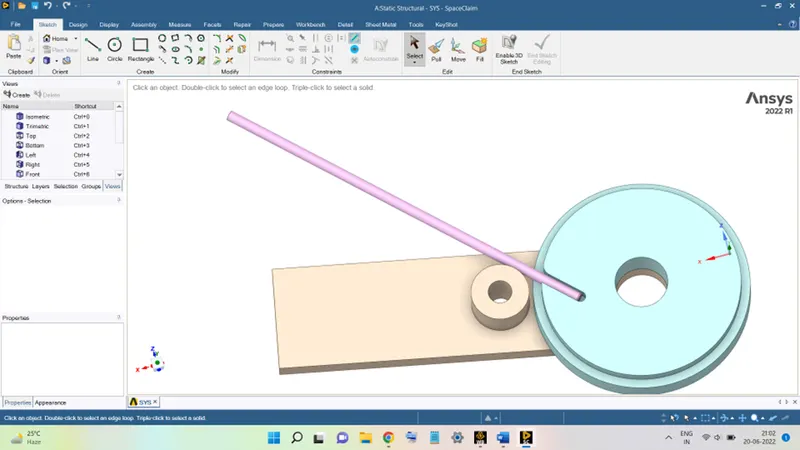
Check for any abnormalities if present in the geometry.
Next, right-click on Model and select Edit to launch the Mechanical Module and load the geometry in the module.
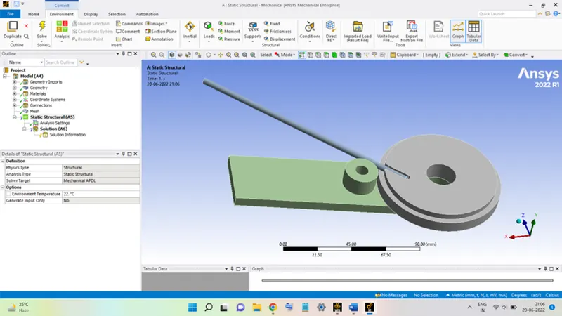
After it, the first thing to do is to expand the Geometry option and rename the parts as shown in the below figure:
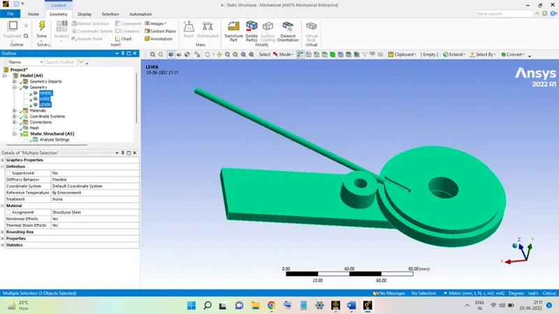
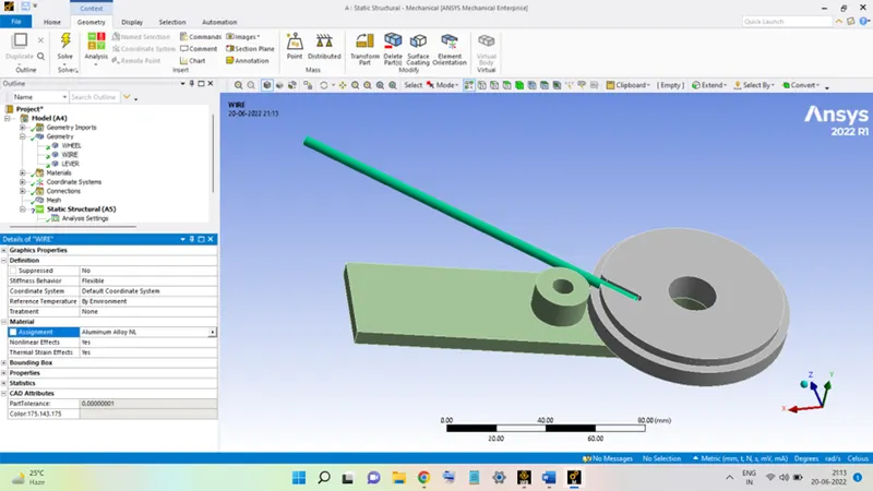
Now, select the WIRE and assign the Aluminium Alloy NL material to it.
In the Connections section, go to Contacts and delete the first two contacts between the WHEEL and WIRE contact and WHEEL and LEVER contact.
Select the remaining contact, between the WIRE and LEVER, and duplicate it, then, flip the duplicated contact.
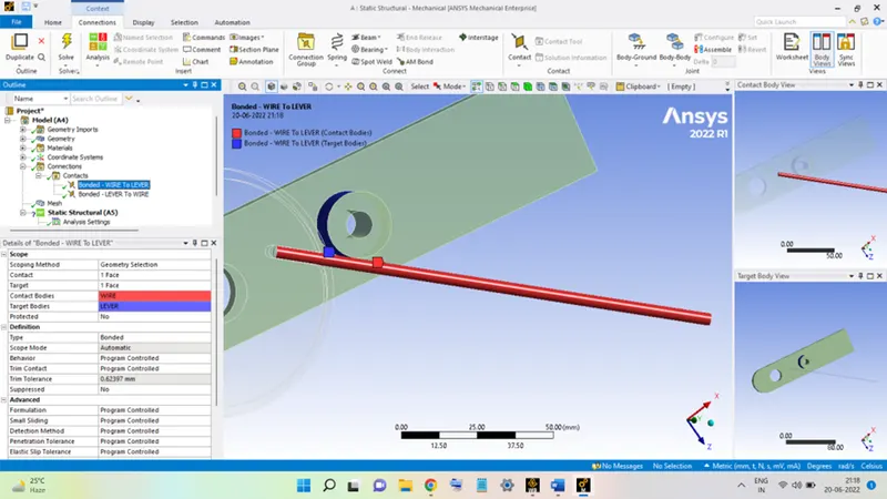
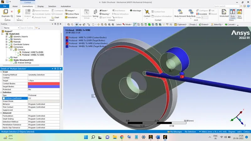
In the LEVER to WIRE contact and select the surfaces of the WHEEL as the Contact bodies, as shown below:
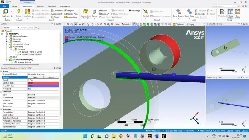
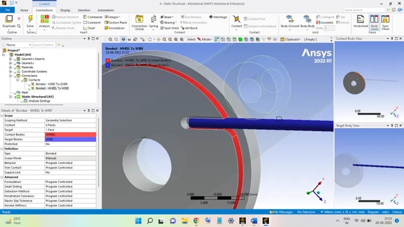
Now, there are two contact regions associated with the WIRE shown in the figure.
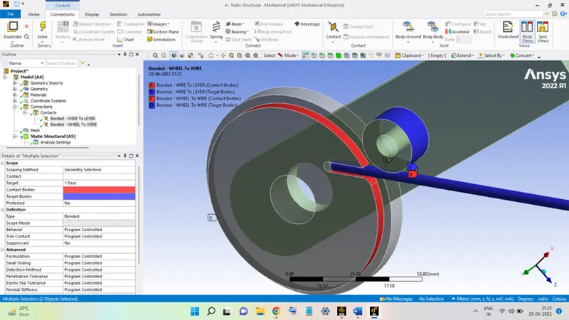
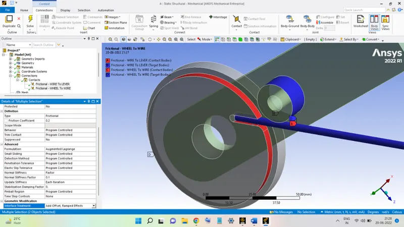
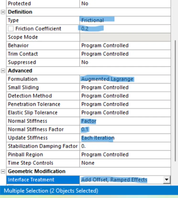
Now, change the type of both the contacts to Frictional and set the Friction Coefficient equal to 0.2.
Now, the geometry is to have meshed.
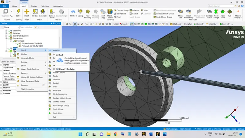
First, right-click on Mesh, go to Insert, and select Method. Select all the bodies in the geometry click Apply and then in Method select Tetrahedrons.
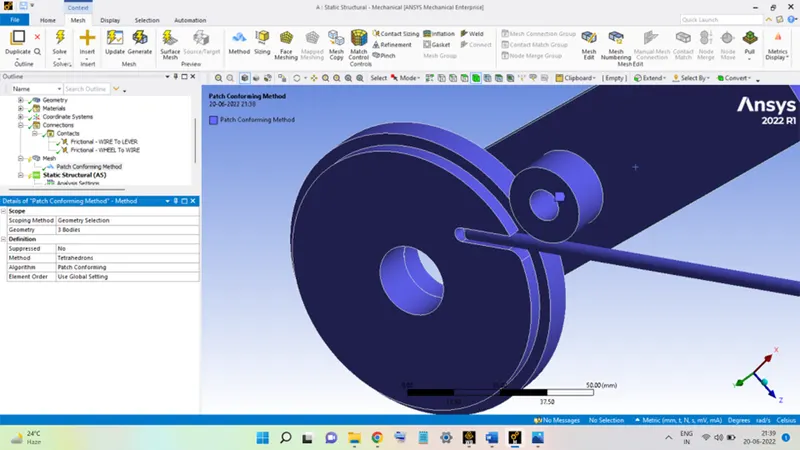
Next, choose Sizing and select the surfaces shown in the figure below hit Apply. Enter the Element Size as 2.2 mm.
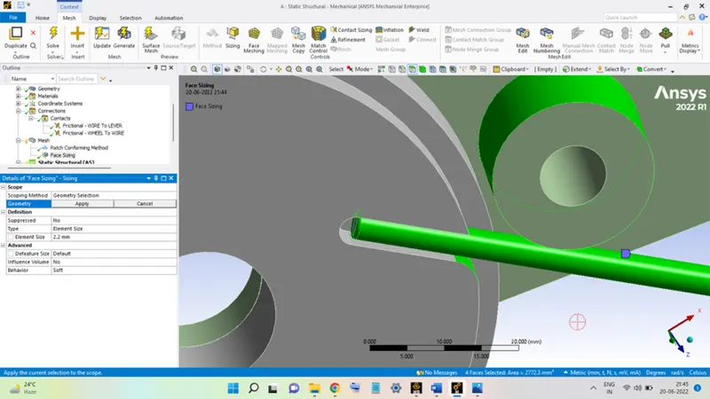
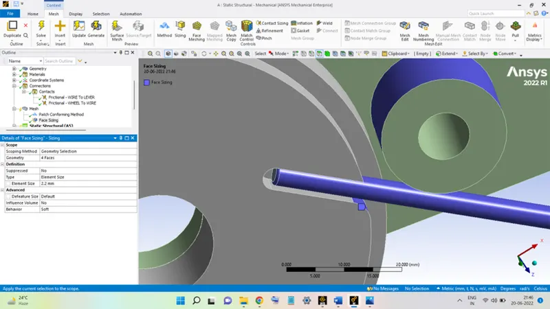
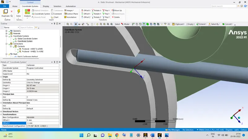
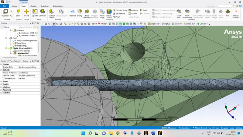
The curved area on the WHEEL near the WIRE is very crucial in wire bending operation, so a finer mesh is to be provided in this area. This is done by, first generating a new coordinate system on this surface and then adding a SPHERE OF INFLUENCE in this area.
To add the coordinate system, select the area and right-click and select Create Coordinate System.
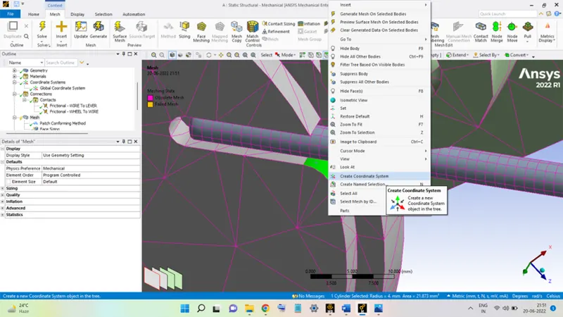
Then select the X Offset first and then Z Offset. Put X Offset = 3 mm; Z Offset = -3 mm.
Now, select the Sizing option then select the WIRE surface and hit Apply.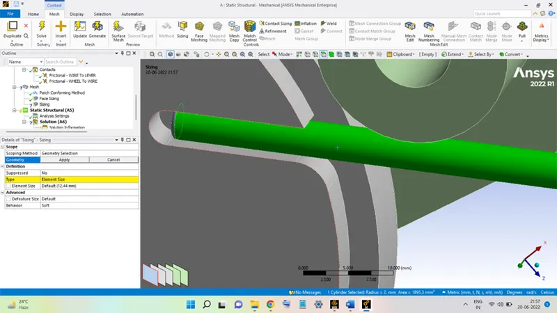
Go to the Definition section, and change the Type to Sphere of Influence as shown above.
Next, set the center of the sphere at the newly created coordinate system.
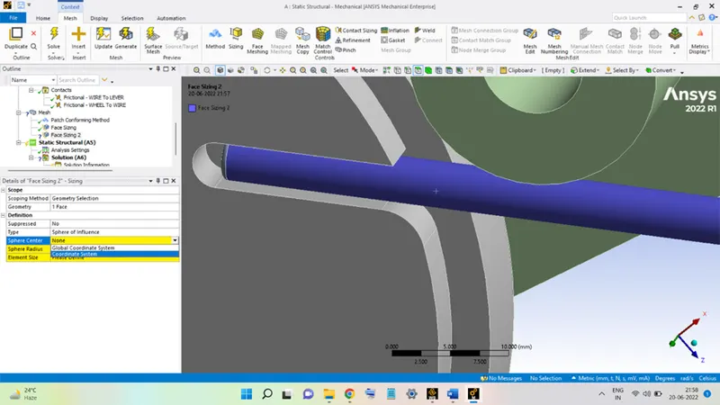
Finally, give Sphere Radius equal to 7 mm and the Element Size is taken as 0.8 mm. The sphere will be created as shown in the figure below.

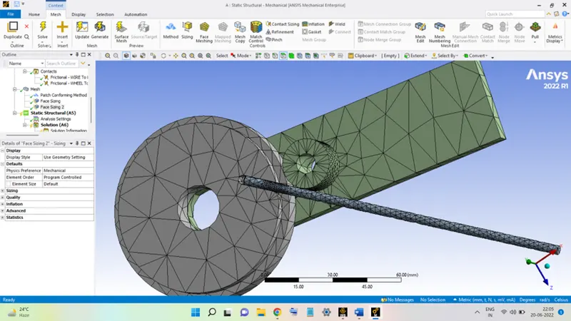
In the Quality section, change Smoothing to Low. Right-click and select Generate Mesh, the mesh will look like this:
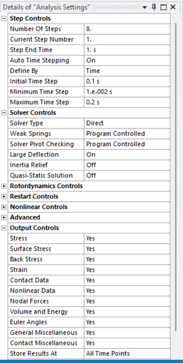
Now, the geometry is to be supplied with the Analysis Settings. In the Analysis Settings:
Number of Steps = 8
For first Step:
Auto Time Stepping = ON
Defined By = Time
Initial Time Step = 0.1 sec.
Minimum Time Step = 0.01 sec.
Maximum Time Step = 0.2 sec.
In Solver Controls,
Solver Type = Direct.
Weak Springs = Program Controlled.
Large Deflection = ON.
Turn ON all the Output Controls options.
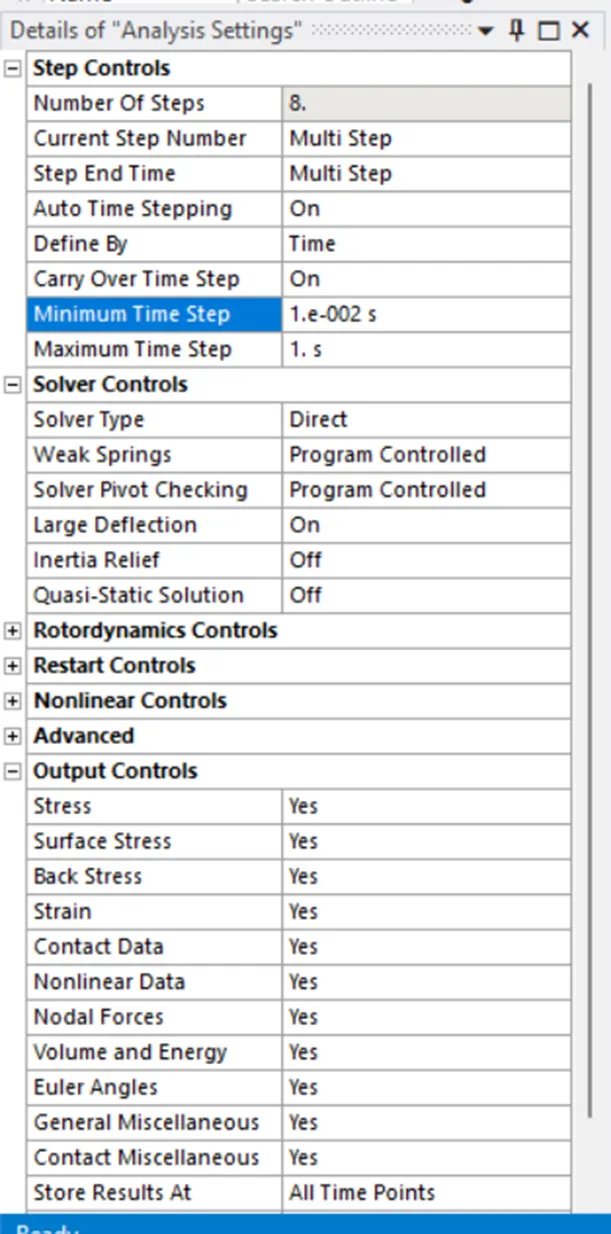
For the rest Steps:
Auto Time Stepping = ON
Defined By = Time
Carry Over Time Step = ON
Minimum Time Step = 0.01 sec.
Maximum Time Step = 1 sec.
In Solver Controls,
Solver Type = Direct.
Weak Springs = Program Controlled.
Large Deflection = ON.
Turn ON all the Output Controls options.
now the next step is to apply loads to the geometry.
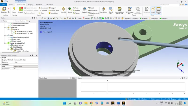
Provide fixed support on WHEEL:
The inner region of the WHEEL is fixed by right-clicking on Analysis Settings and going to the Insert option and selecting the Fixed Support.
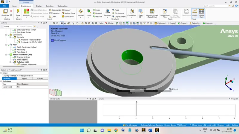
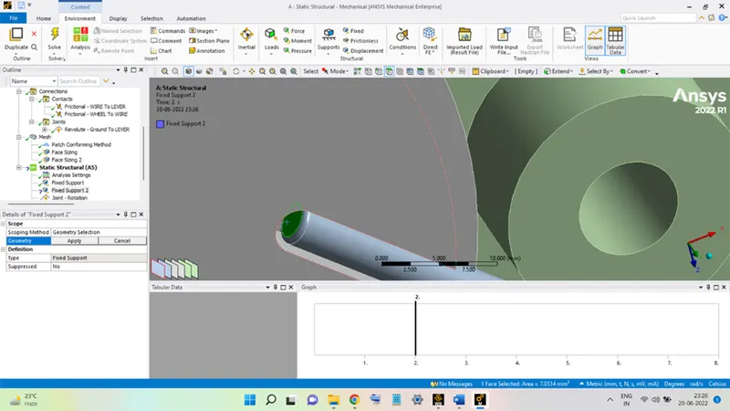
Apply Fixed Support to the face of the WIRE:
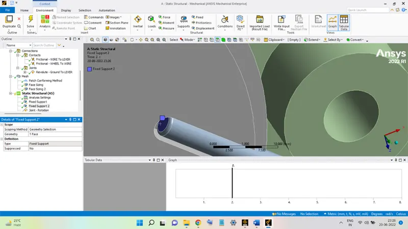
Select the inner wire face, as shown in the figure below, and click on Analysis Settings and select the Fixed Support, hit Apply to fix the face.
Provide Revolute Joint on LEVER:
Now, give a revolute joint to the LEVER, right-click on Connections, go to Insert, and select the Joint Load. Change the Connection Type as Body-Ground and Type as Revolute.
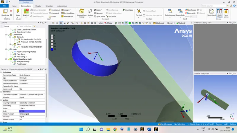
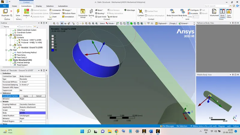
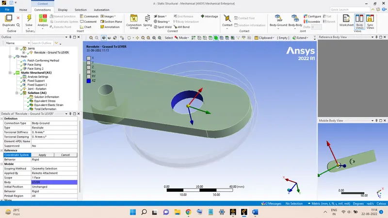
Now, flip the Z-Axis to the opposite side and interchange X-Axis and Y-Axis by clicking on Coordinate System and selecting the respective axes and the direction it must be flipped to, and then hit Apply.
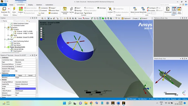
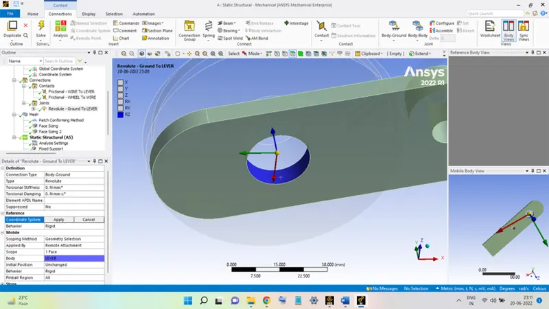
The changed coordinate system of the revolute joint at the LEVER is shown in the figure below:
Add the Rotation to the revolute joint. Right-click on Analysis Settings, go to Insert, and select Joint Load.
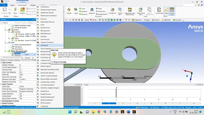
Select the Joint as Revolute – Ground To LEVER, in the Definition section, select Type as Rotation and Magnitude as Tabular Data. Enter the values for each step as shown in the figure.
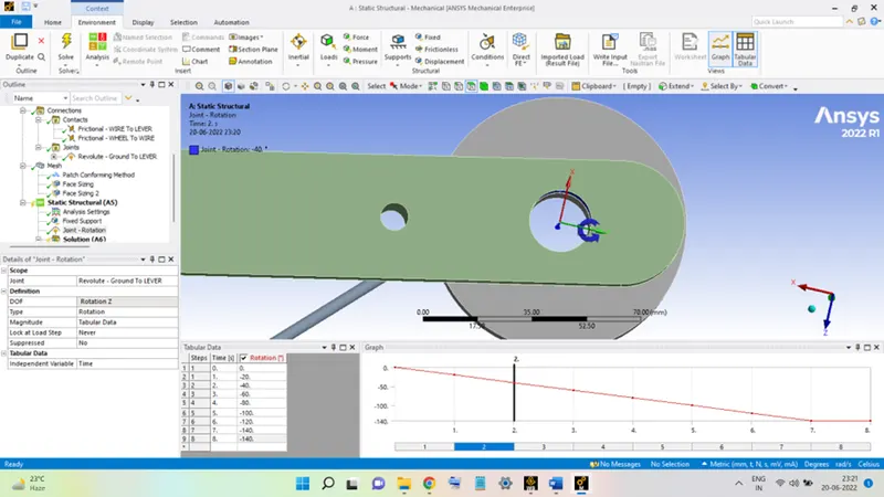
Now the geometry is ready for the analysis, click on Solve to start the analysis.
RESULTS:
Aluminium Alloy NL:
Stress:
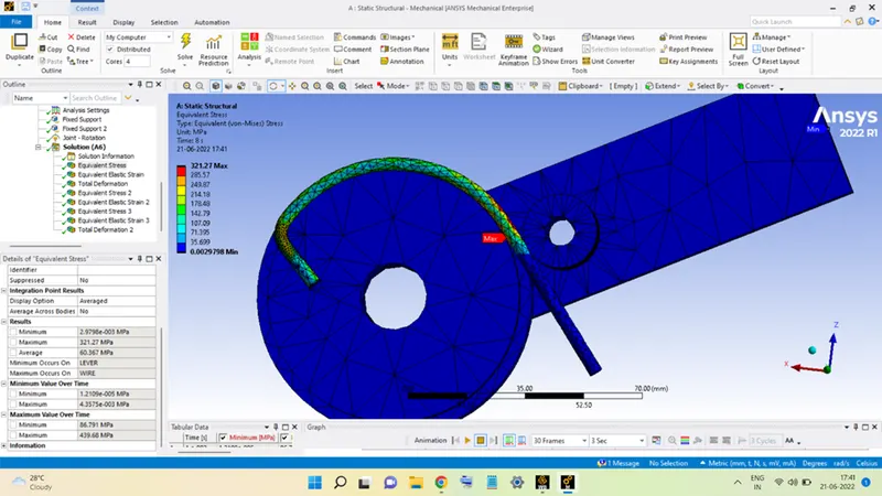
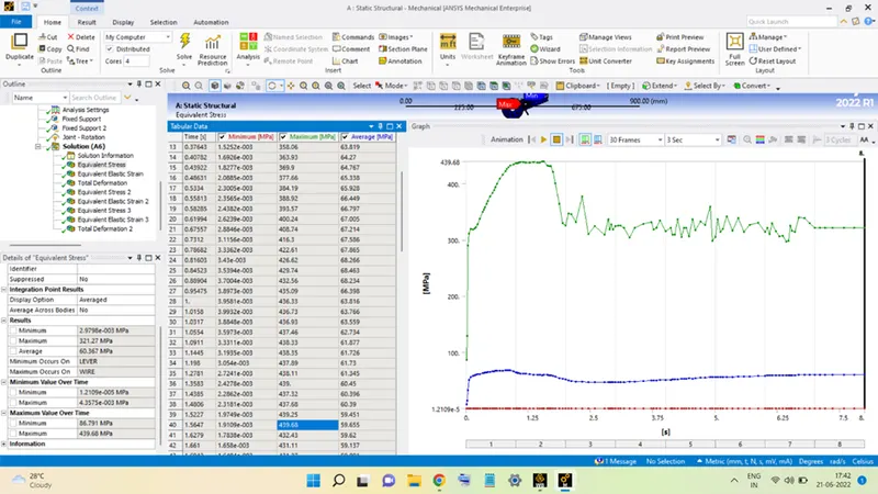
The stress developed in the wire throughout the wire bending process is shown in the figures above. The stress during the process attains a maximum value of 439.68 MPa.
Strain:
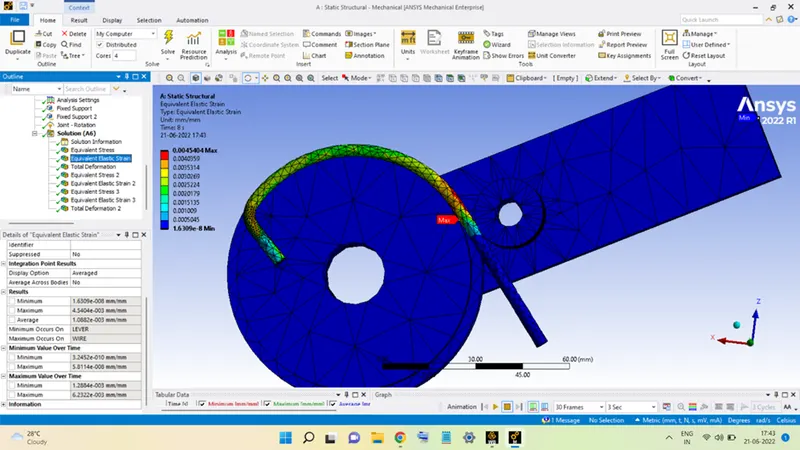
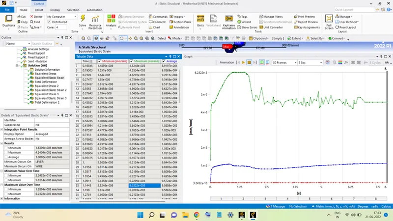
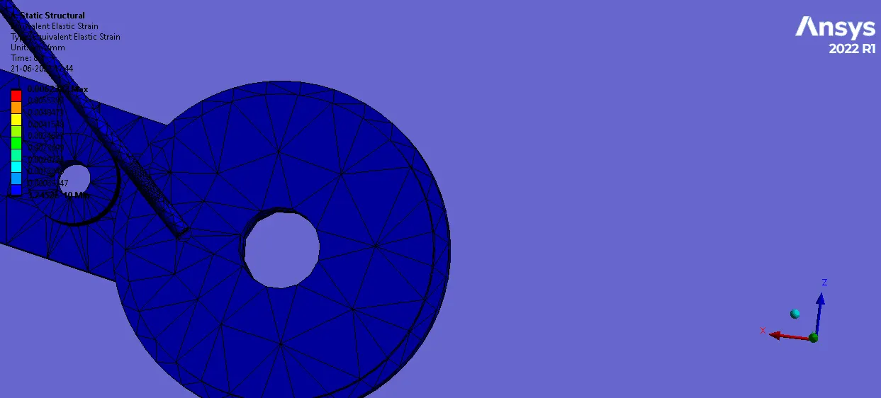
The equivalent strain developed in the wire throughout the wire bending process is shown in the figures above. The strain during the process attains a maximum value of 6.2322 x 10⁻³.
Stress in Wire:
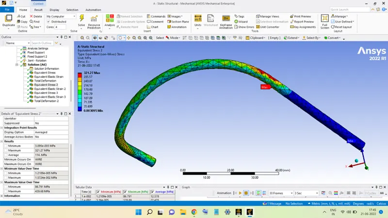
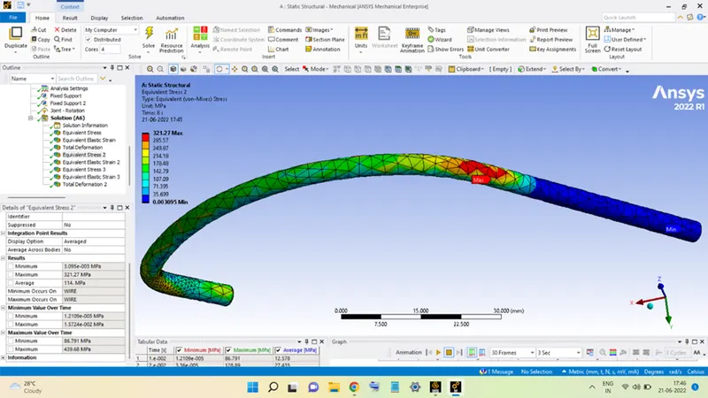
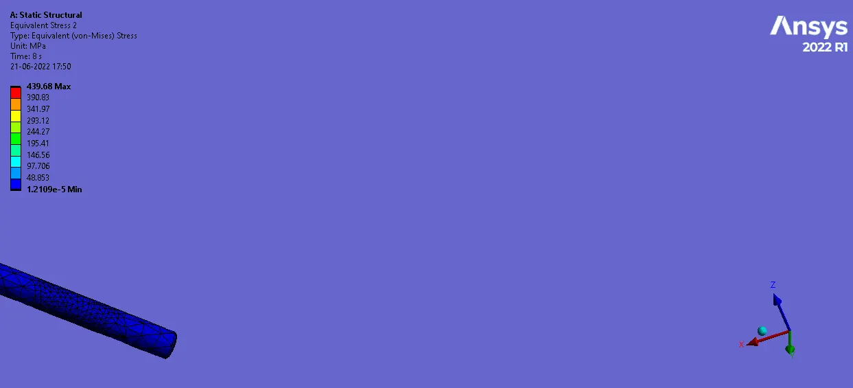
The equivalent strain developed in the wire throughout the wire bending process is shown in the figures above. The strain during the process attains a maximum value of 439.68 MPa.
Strain in Wire:
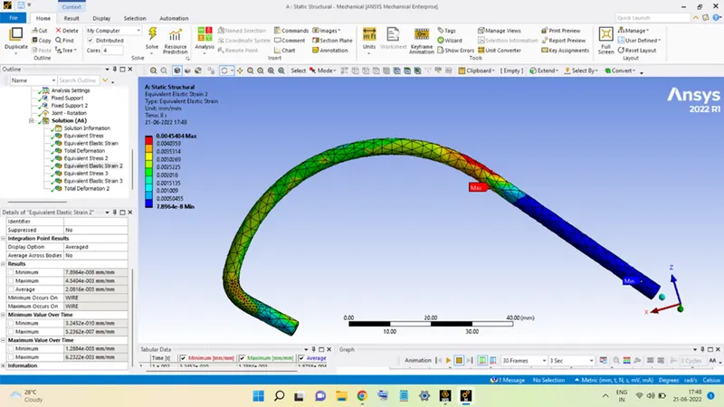
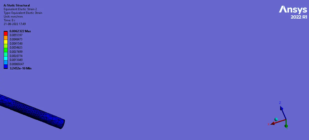
The equivalent strain developed in the wire throughout the wire bending process is shown in the figures above. The strain during the process attains a maximum value of 6.2322 x 10⁻³.
Total Deformation:
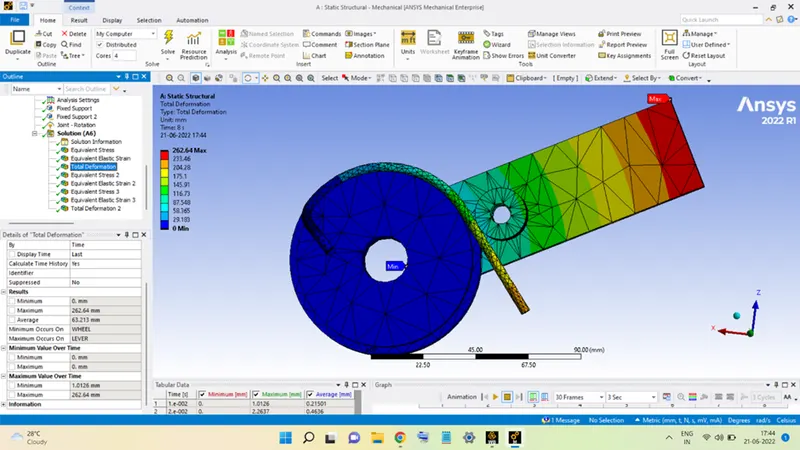
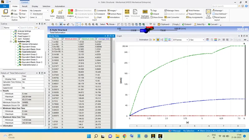
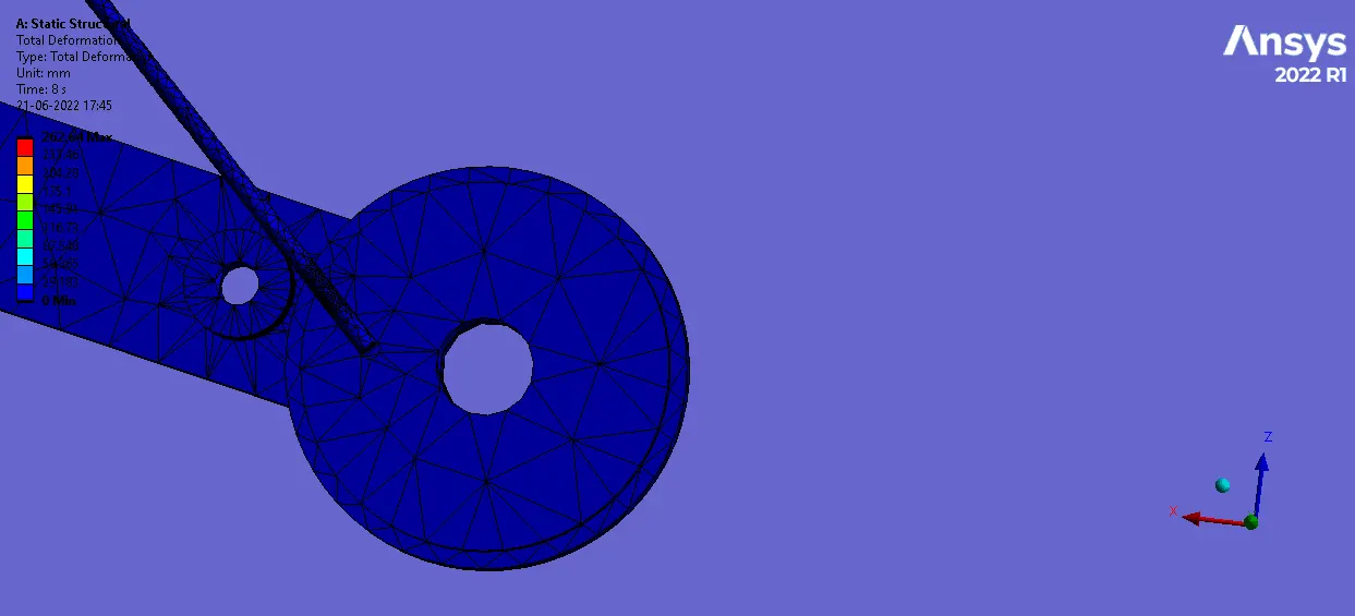
The deformation occurring in the wire bending operation is shown above. The maximum deformation is equal to 262.64 mm.
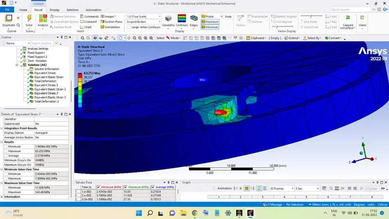
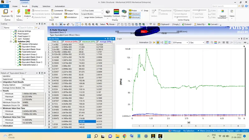
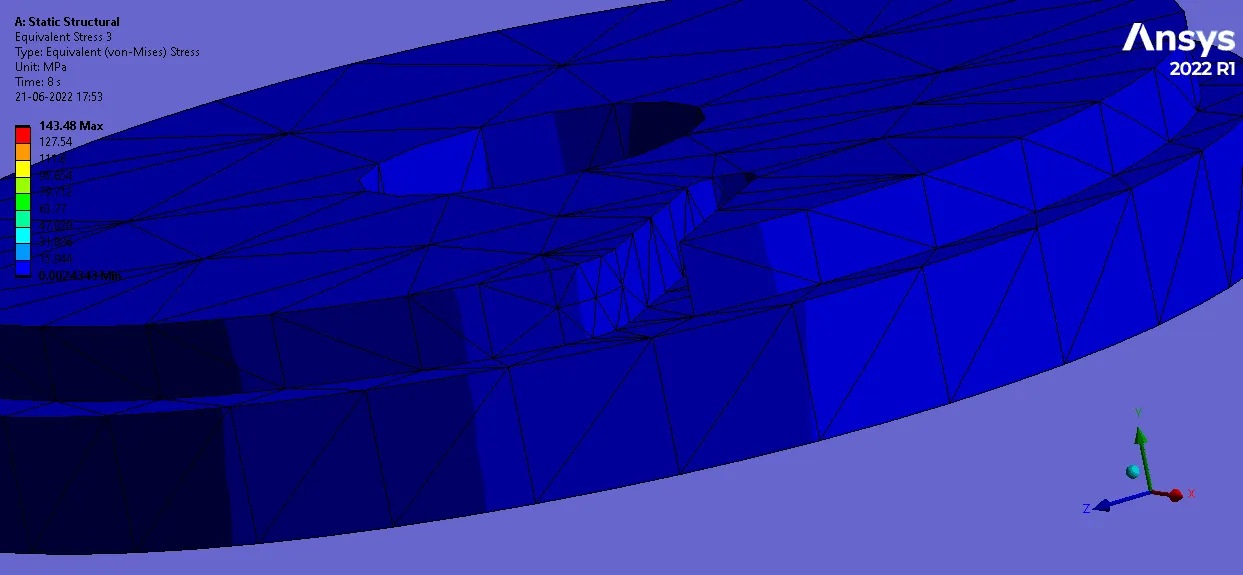
Stress in Wheel:
Strain in Wheel:
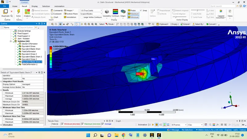
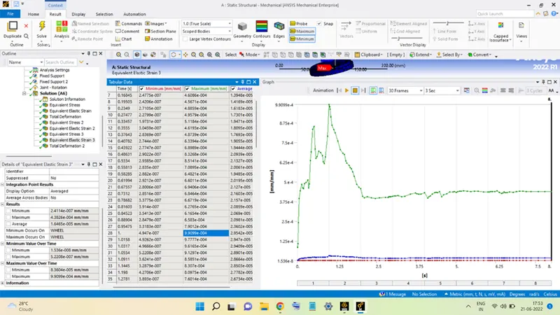
CASE 2: COPPER ALLOY NL
Stress:
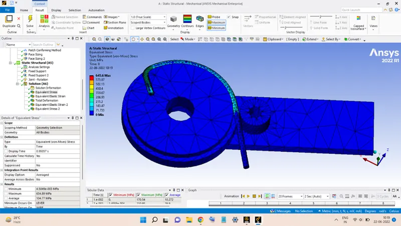
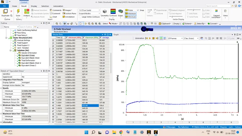
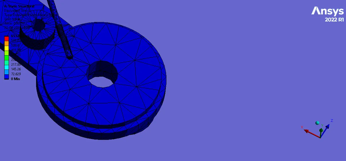
The stress developed in the wire throughout the wire bending process is shown in the figures above. The stress during the process attains a maximum value of 653.66 MPa.
Strain:
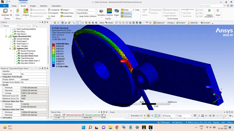
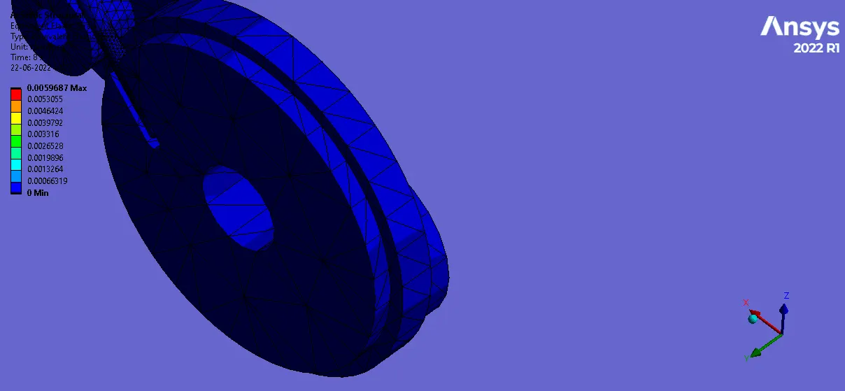
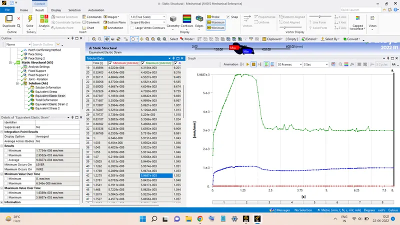
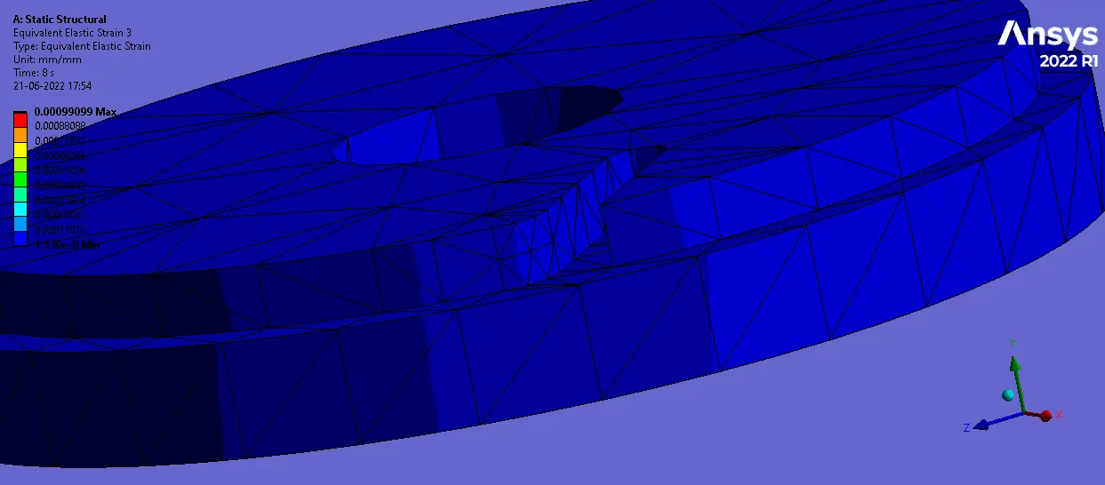
The equivalent strain developed in the wire throughout the wire bending process is shown in the figures above. The strain during the process attains a maximum value of 5.9687 x 10⁻³.
Stress in Wire:
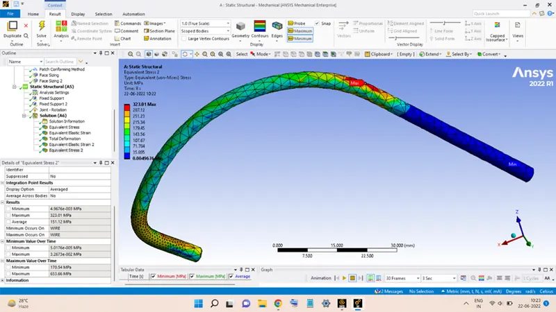
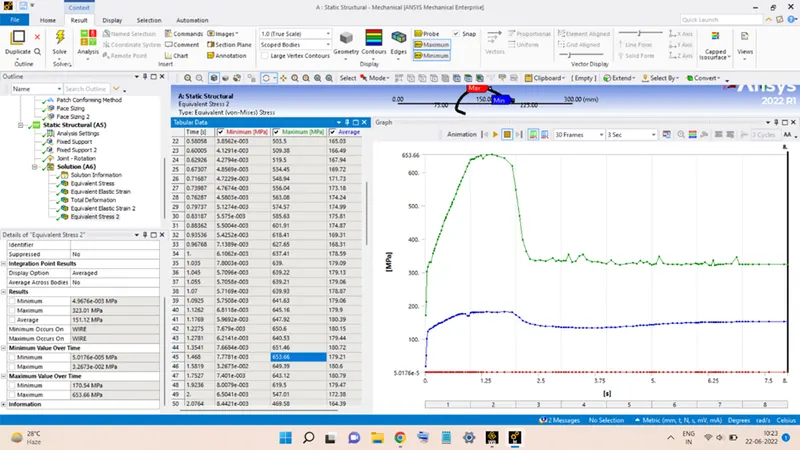
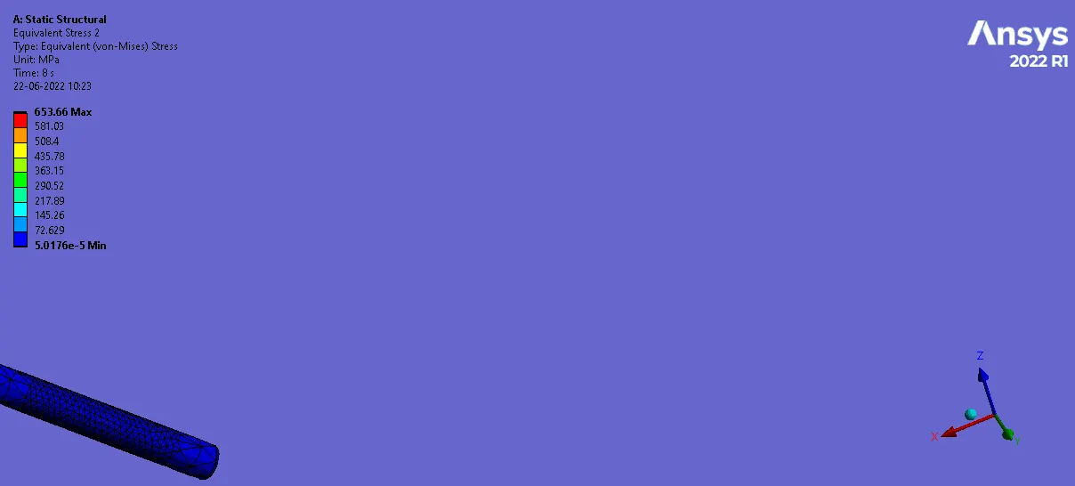
The variation of the stress in the wire during the wire bending operation is shown above. the maximum stress in the wire during the operation is equal to 653.66 MPa.
Strain in Wire:
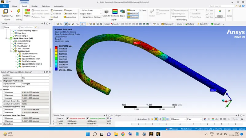
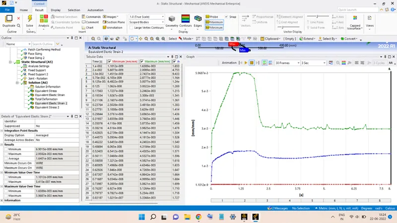
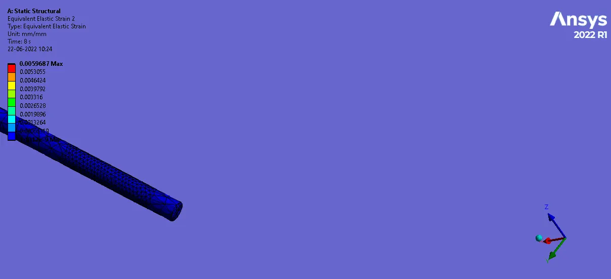
The above figures show the variation of the strain developed in the wire during the wire bending operation, the maximum strain value in the wire is equal to 5.9687 x 10⁻³.
Total Deformation:
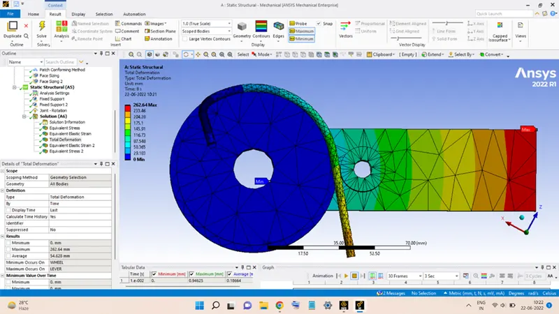
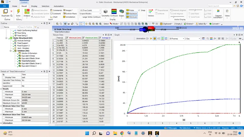
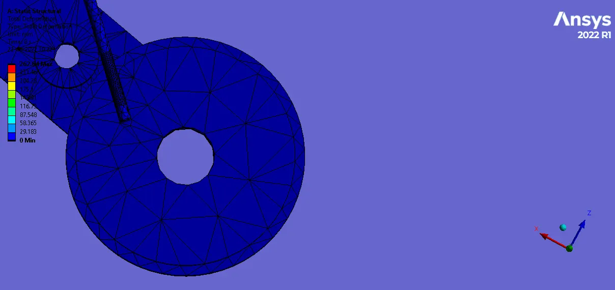
The deformation occurring in the wire bending operation is shown above. The variation is similar to that in the previous case and the maximum deformation is also the same, 262.64 mm.
CASE 3: MAGNESIUM ALLOY NL
Equivalent Stress:
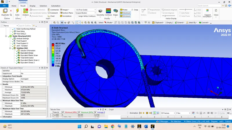
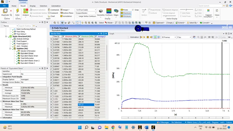
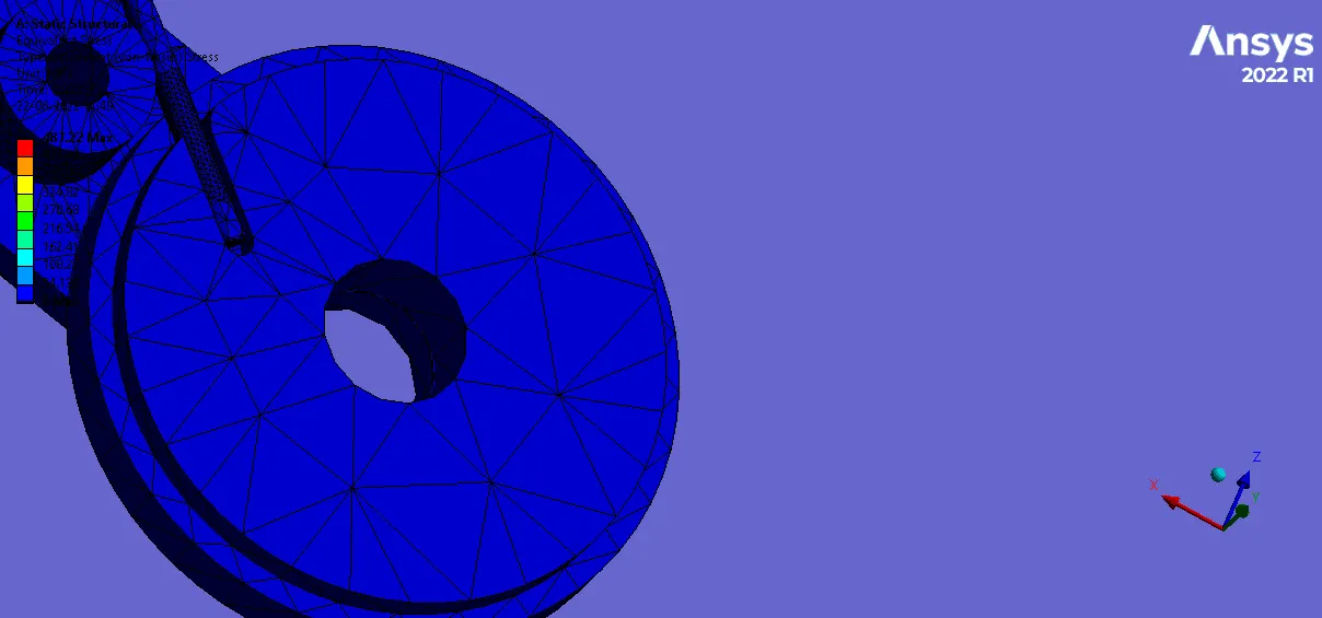
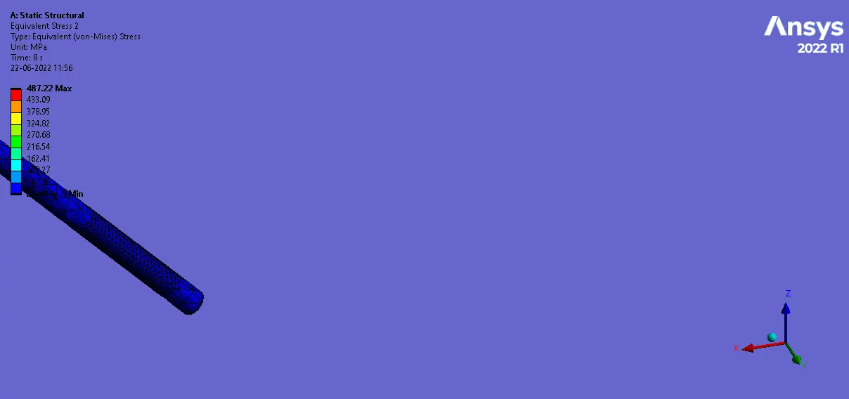
The stress developed throughout the wire bending process is shown in the figures above. The stress during the process attains a maximum value of 487.22 MPa.
Equivalent Strain: 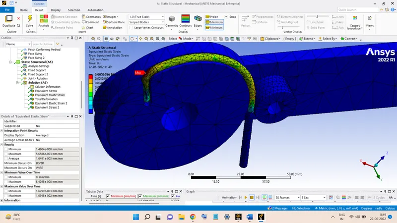
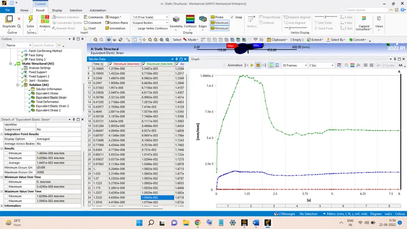
The equivalent strain developed throughout the wire bending process is shown in the figures above. The strain during the process attains a maximum value of 5.9687 x 10⁻³.
Stress in Wire:
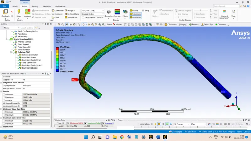
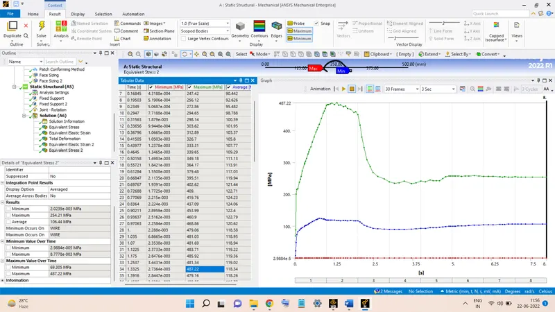
Strain in Wire:
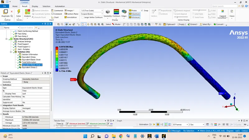
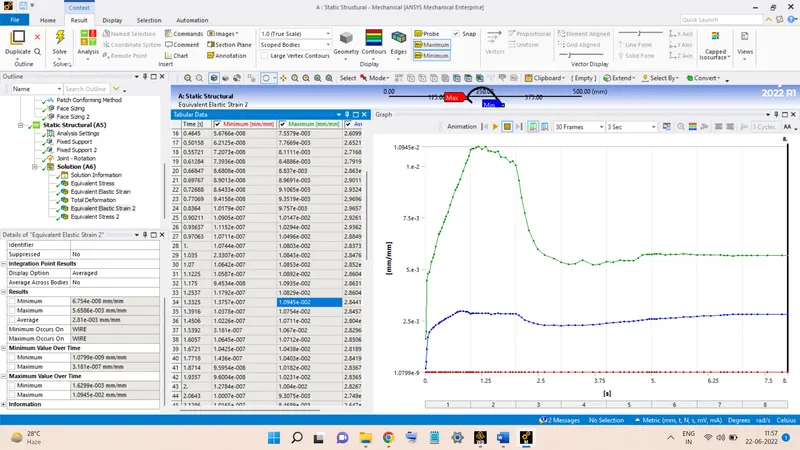
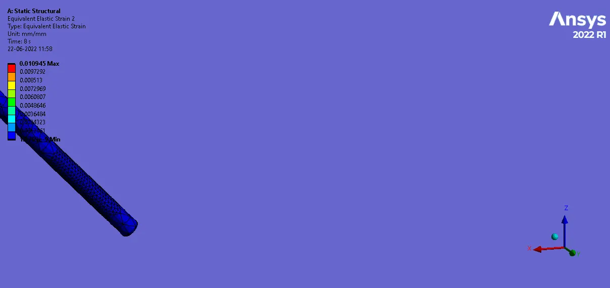
The equivalent strain developed in the wire throughout the wire bending process is shown in the figures above. The strain during the process attains a maximum value of 1.0945 x 10⁻².
Total Deformation:
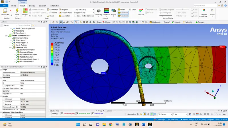
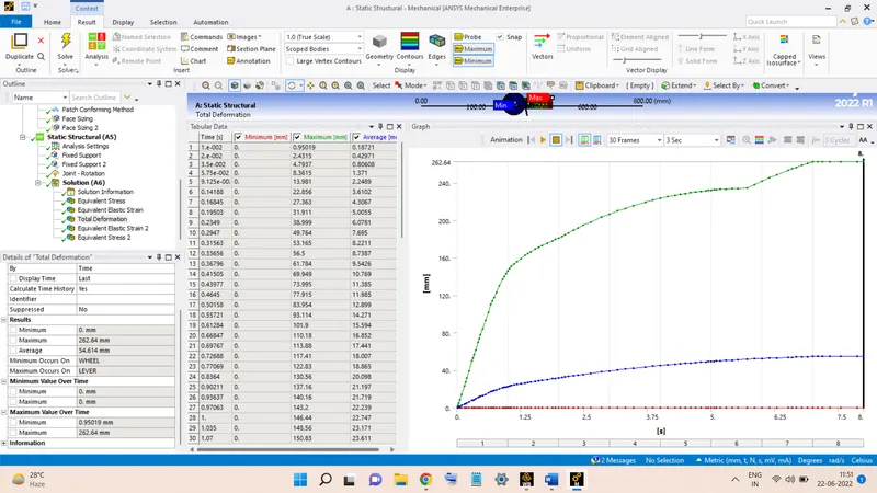
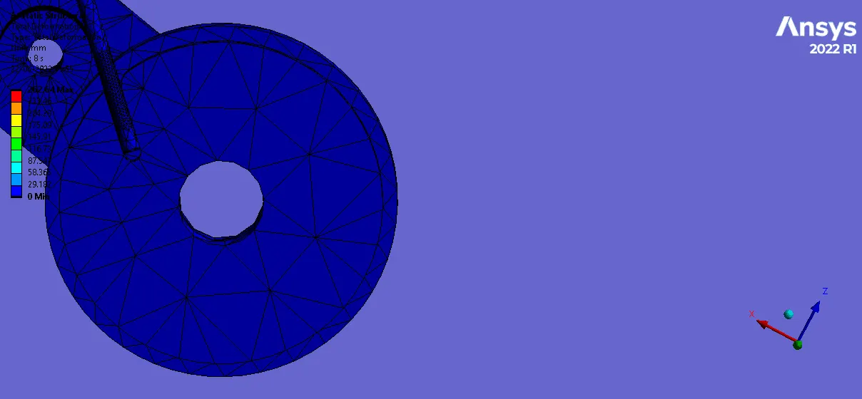
The deformation occurring in the wire bending operation is shown above. The variation is similar to that in the previous case and the maximum deformation is also the same, 262.64 mm.
Comparison:
|
|
MAX. STRESS IN WIRE (MPa) |
MAX. STRAIN IN WIRE |
|
ALUMINIUM ALLOY NL |
439.68 |
6.2322 x 10⁻³ |
|
COPPER ALLOY NL |
653.66 |
5.9687 x 10⁻³ |
|
MAGNESIUM ALLOY NL |
487.22 |
1.0945 x 10⁻² |
1. The Copper Alloy is most difficult to deform since the stress required to bend the copper wire is maximum in all three wires. Aluminium Alloy wire is readily deformable with the least stress required.
2. The Magnesium Alloy wire shows the highest amount of strain developed among the three wires, followed by Copper wire and then Aluminium wire with the least of all.
3. from the above results, the Aluminium Alloy NL wire is the best pick for the wire since it requires less force to get deformed. The Magnesium Alloy NL should not be taken since for the similar loads as applied on Aluminium Alloy, the Magnesium wire will exhibit a huge amount of strains developed within it. This may lead to premature failure of the wire.