Week 4- Rolling operation
Rolling Operation in Ansys
Objective
Simulate a rolling operation of the given workpiece ( Copper ) and infer the results.
Briefing
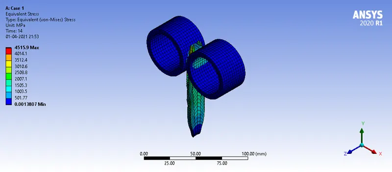
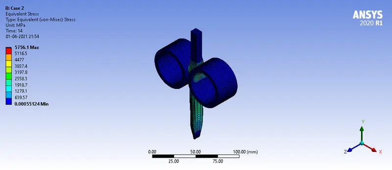
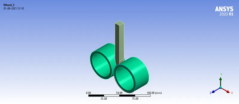
The model consists of 3 parts - 2 rollers and the workpiece.
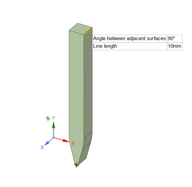
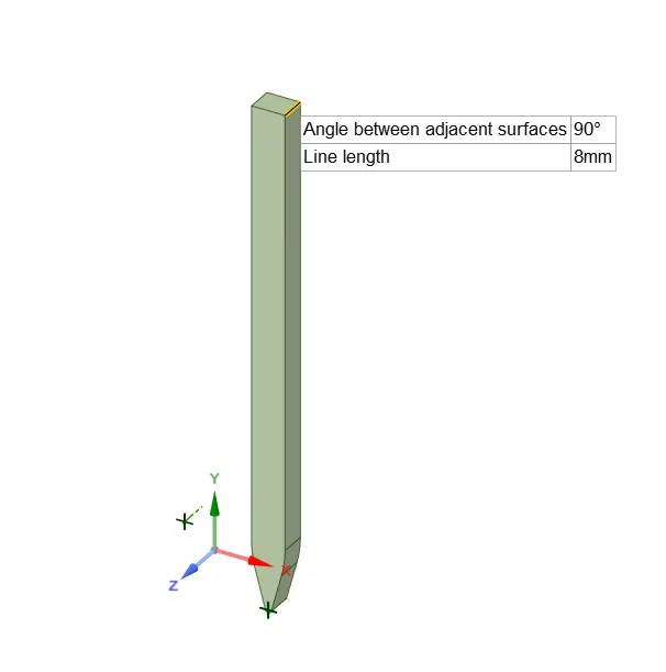
For case 1 the workpiece with 90mm is used and for case 2 with a length of 150mm is used.
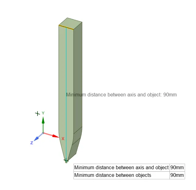
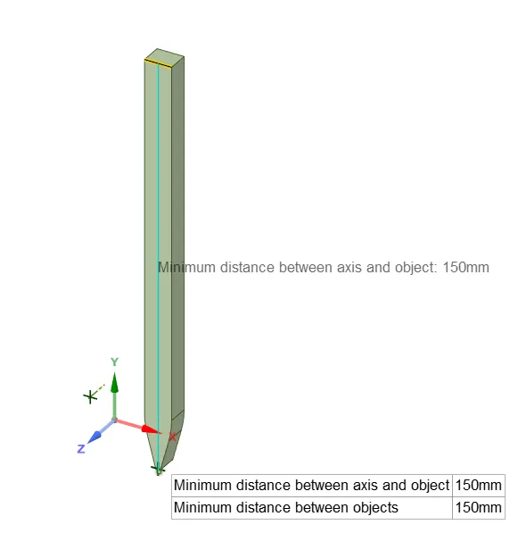
Width of the workpiece with reduced by 2mm for case 2. ( Operations performed in Spaceclaim).
Procedure and Setup
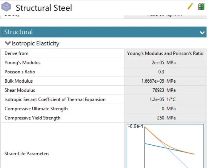
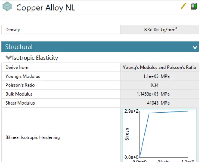
- Wheels are assigned with structural steel and the workpiece is given copper alloy non - linear.
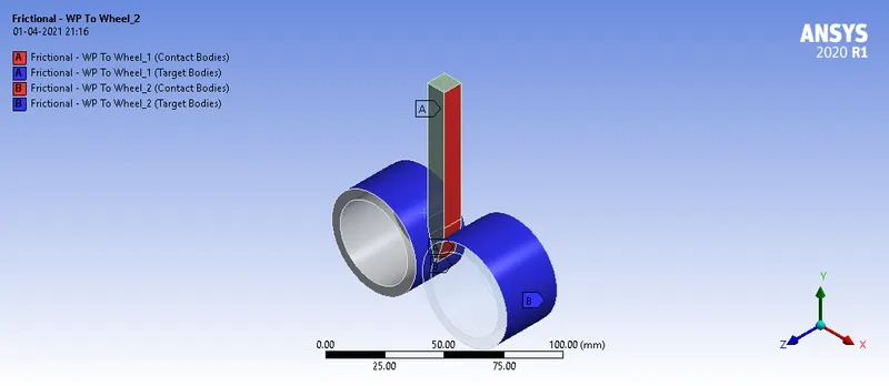
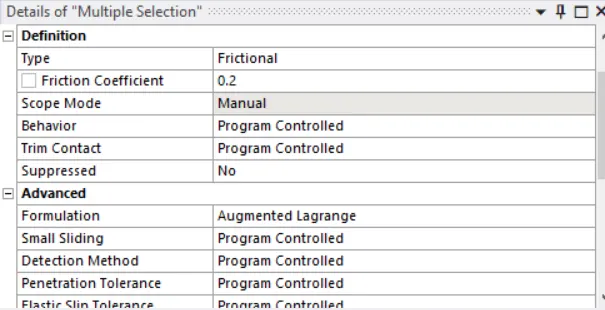
Contact Definition: Frictional contacts are defined between workpiece and wheel contact surfaces.
With Frictional Coefficent = 0.2;
Augmented Lagrange Formulation;
Normal Stiffness behavior factor = 0.1;
Interface Treatment as Add offset, ramped effects
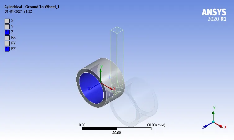
Joints Definition: both the wheels are given cylindrical joints
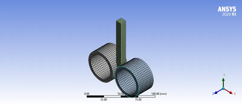
Meshing - Default Mesh parameter used with element size as 3mm.
Boundary Conditions
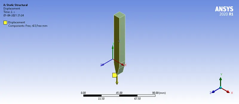
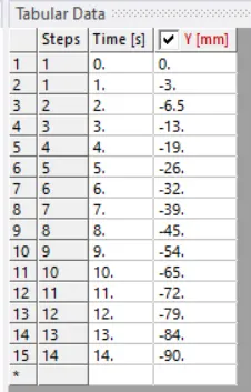
Displacement is given to the workpiece on the z-axis, in 15 load steps.
The wheels are given rotation in degrees in opposite directions in order to pull the workpiece.
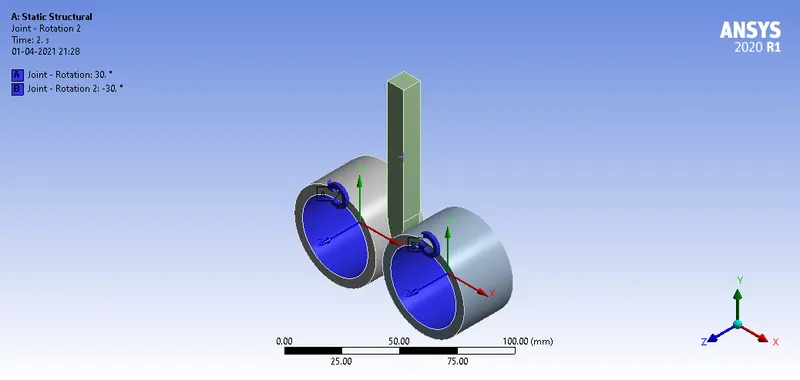
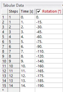
Analysis Settings: Program Controlled Approach is used for this case and large deflections are turned on.
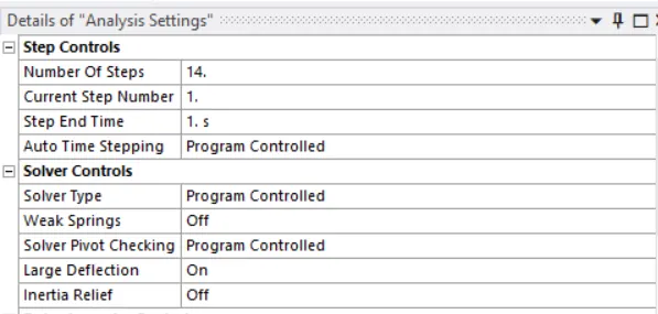
Results and Conclusion:
| Cases / Parameters | Equivalent stress for the whole setup ( MPa) (Max) |
Equivalent Plastic strain for the workpiece (Max) |
Directional Deformation in the Z-axis for the workpiece ( Max) |
| Case 1 ( 90 x 10 mm) | 8135.9 MPa | 3.0073 mm/mm | 7.921 mm |
| Case 2 ( 150 X 8 mm) | 8366.2 MPa | 2.1415 mm/mm | 6.4389 mm |
- The workpiece has undergone plastic deformation (Yield stress of Copper = 280 MPa) and maximum stress is developed in the workpiece.
- In case 1 has undergone more plastic strain than case 2.
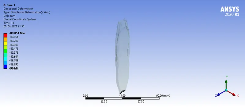
- In both cases, the workpiece is displaced by 90mm.