Week 4- Rolling operation
- Objective:-
To simulate a rolling operation by passing a thicker copper block through two rollers and obtaining the equivalent stress, equivalent plastic strain and directional deformation plots of the workpiece.
- Model Details:-
Following model has been provides, with two rollers and a copper alloy workpiece in between them. As mentioned in the challenge, first the workpiece is edited in Spaceclaim (length increased by 60 mm and width decreased by 8 mm on both sides) and then the whole model is opened in Mechanical workbench.
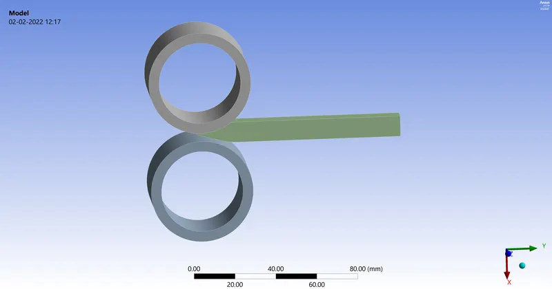
Workpiece has been assigned Copper alloy NL as the material from the General Non-linear materials library.
All the contacts of the rollers with their respective surfaces on the workpiece are assigned as Frictional with coefficient as 0.2.
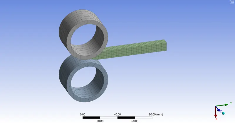
The workpiece is meshed using 2 mm Body Sizing, while the rest of the parts are meshed using default settings. Total number of elements is 1629 and the total number of nodes in the mesh is 9321.
- Loads and Constraints:-
To perform the rolling operation, we have to push the workpiece in the negative Y direction and hence the following displacement are given to the workpiece, we are doing the simulation in 14 time steps.
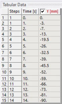
So we are moving the workpiece by 90 mm in the negative Y direction in this simulation. We also rotate the cylinders in 14 time steps, and their angular rotation table is as shown below. Both have same magnitudes, but top wheel rotates clockwise and bottom wheel rotates anti-clockwise (hence negative values).
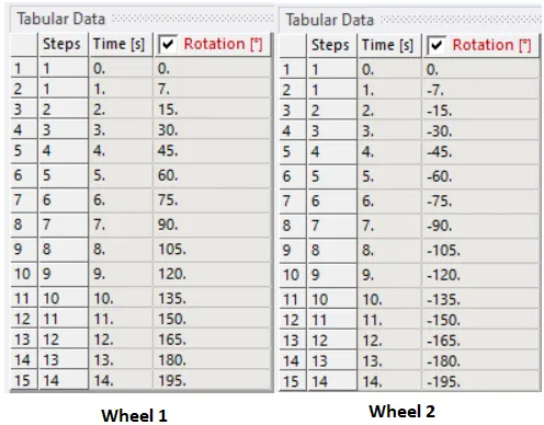
To avoid the slipping of the workpiece or the rollers, I added Displacement load to both the rollers which restricted their motion along Z-axis, while in X and Y axis they were free. After implementing this constraint, there was no slipping and I received proper results of the rolling operation.
- Results:-
Animation files of the results are linked below,
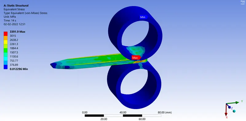
Equivalent stress of the whole setup:- https://youtu.be/YKvnjDjk5jQ
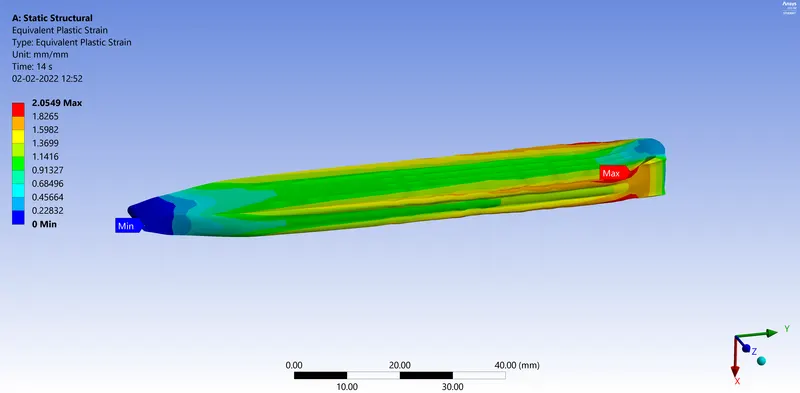
Equivalent plastic strain of the workpiece:- https://youtu.be/pqE01FPZlwU
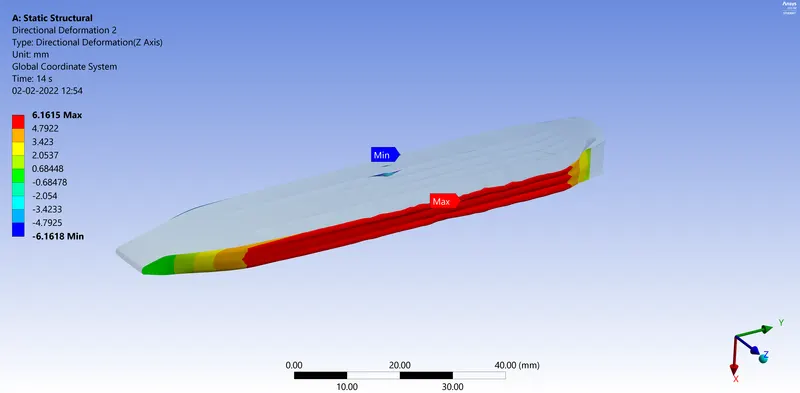
Directional deformation of the workpiece in the Z-axis:- https://youtu.be/34A77Pwmzdk
Equivalent stress of the whole setup:-
Equivalent plastic strain of the workpiece:-
Directional deformation of the workpiece in the Z-axis:-
To verify that our workpiece has actually travelled 90 mm in the negative Y-axis as intended, I have used a Directional Deformation of the front undeformed surface of the workpiece to measure its displacement in the Y-direction, its result is as shown below,
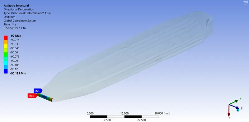
This proves that the workpiece indeed has travelled by 90 mm as intended.
- Conclusion:-
In summary we can conclude that the rolling operation simulation has been successfully performed. Also we have verified the actual travel of the workpiece using the Directional deformation tool. We can see that the initial thickness of 10mm of the workpiece has been reduced to 6 mm, which is the gap between the rollers. Also due to this rolling operation we can clearly see the increase in the width of the workpiece by about 6 mm on either side.