Week 4: Project - Transient simulation of flow over a throttle body
Aim:
In this Project, a transient flow analysis is made on the flow of air through the throttle body.
Theory:
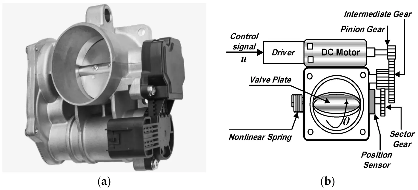
A Throttle valve (a) is used for increasing and decreasing the flow of fuel to the engine where the control signal is send from the motion of accelerator and the further flow control as shown in the following figure(b).
Case Setup:
For this pupose case is setup using the provided geometry.
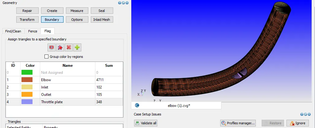
Moreover, its a transient state solution of the throttle valve .
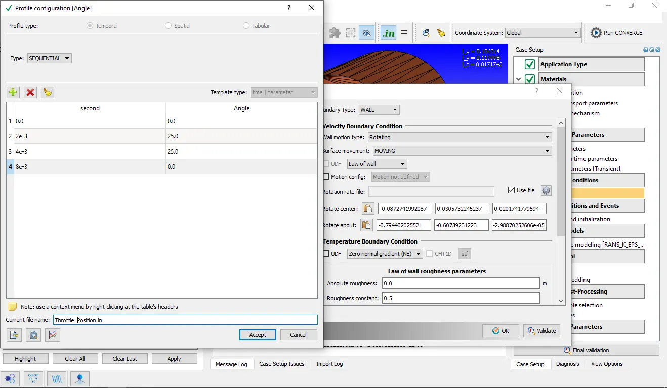
After pre-poscessing using turbulance modelling as RNG k-epsilon, meshing and post processing results are viewed in PARAVIEW.
Mesh:
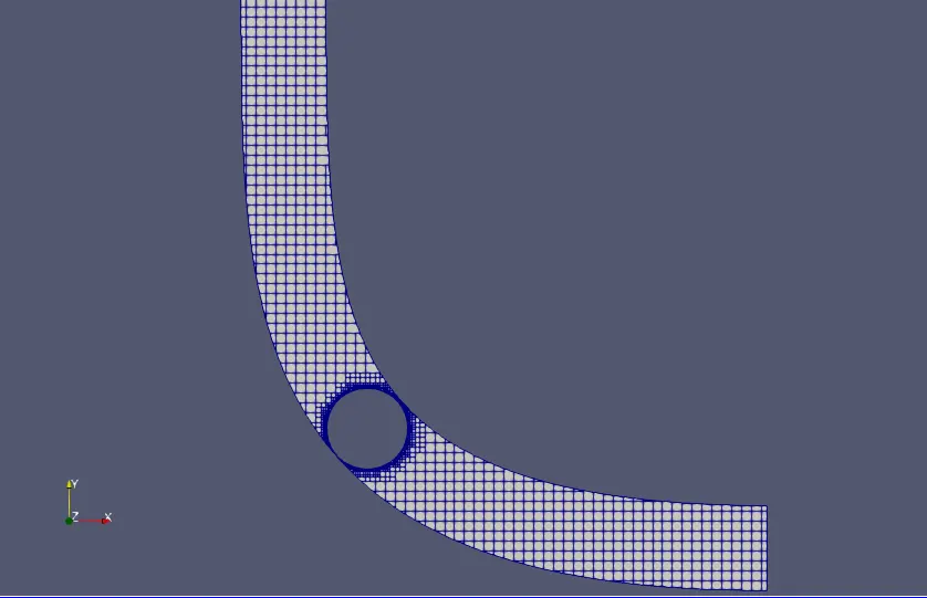
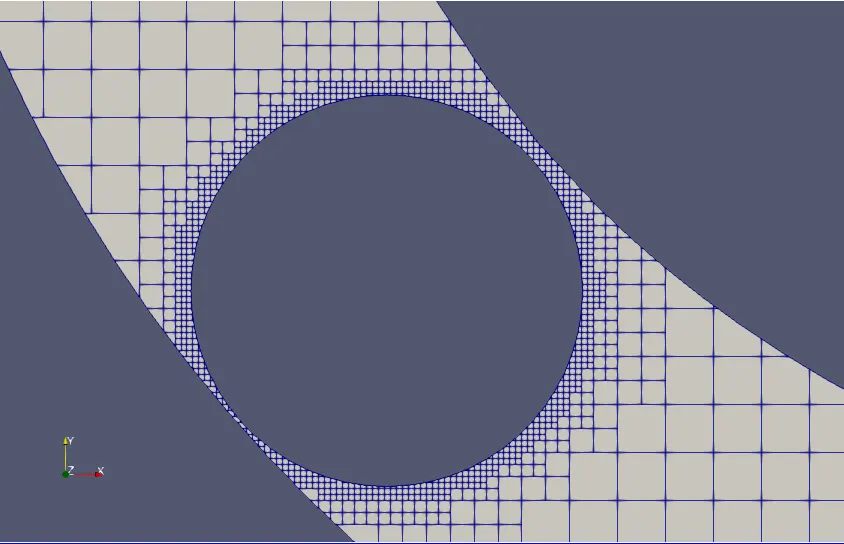
As can be seen from the figure below, fixed embedding is used for meshing purposes around the throttle valve, a base mesh of 2e-03 is used, with the embedding scale of 3.
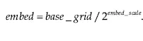
This would definitly increase the number of cells and simulation time but would result in very detailed view around the throttle valve.
Cell Count:
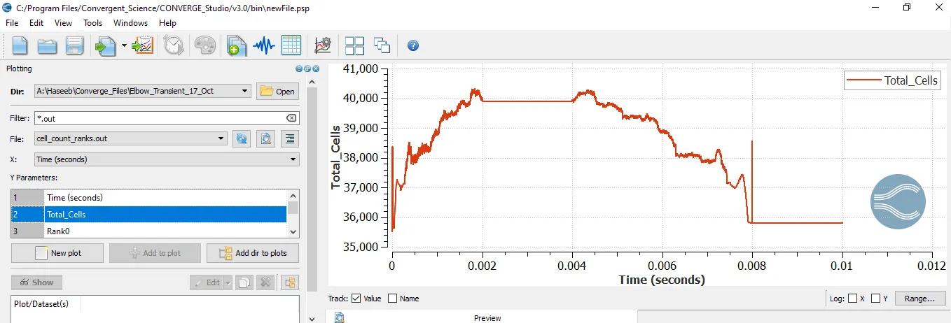
The cell count increases due to the motion of the throttle plate evident from the following figure.
Mass flow rate vs No. of Cycles Plot:
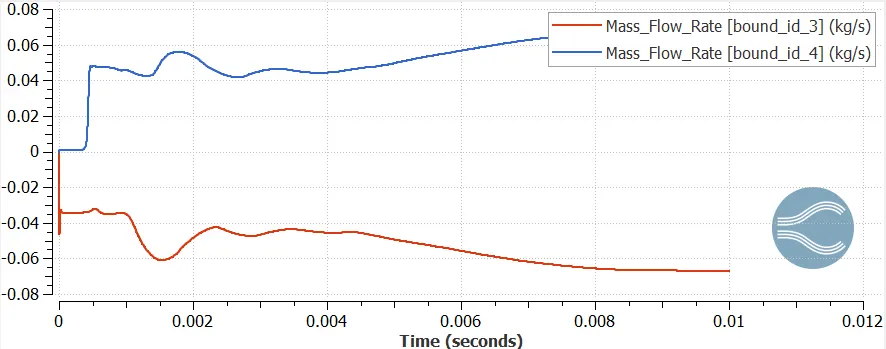
The mass flow rate at the inlet is equal to the mass flow rate at the outflow.
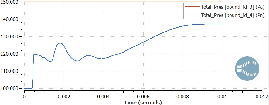
Total Pressure vs No. of Cycle:
The total pressure at inlet is 1.5 bar whereas at the outlet 1 bar was originally set, but due to the transient motion of the throttle plate the pressure keeps on changing during the transition period.
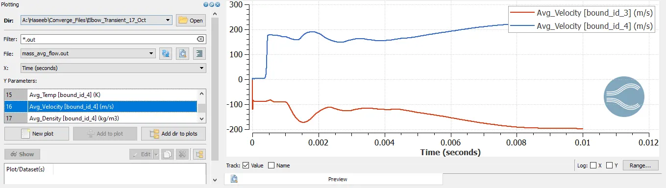
Velocity vs No. of Cycles Plot:
As could be seen the velocity at the inlet is slightly less than that at outlet. It could be said that the small spaces between the throttle plate and the elbow could be the reason for this slight increase.
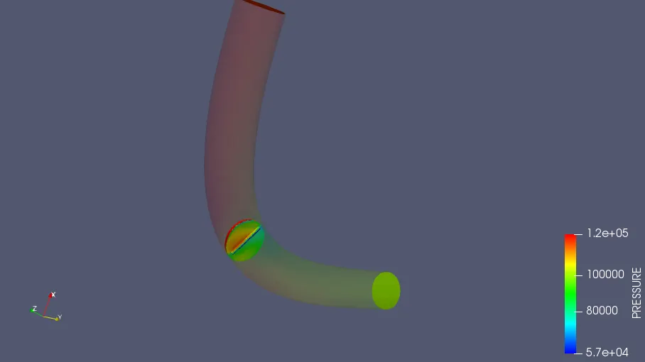
Pressure Contour:
From the following graph, its visible that the pressure that pressure at the upstream of the throttle(where the air strikes before sliding above it) is greater than that of the downstream end and spaces between the throttle plate and elbow.
Link for Pressure Contour:
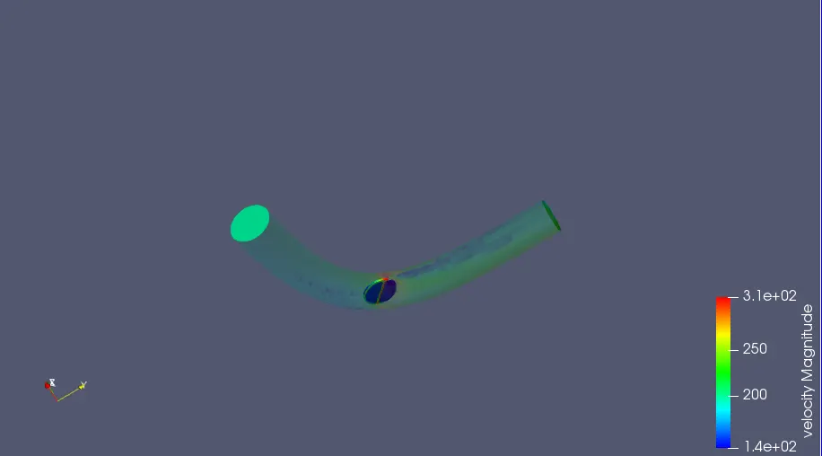
Velocity Contour:
In accordance with the Pressure contour, velocity contour shows that the velocity is comparatively higher at the spaces between the throttle plate and elbow than the striking and trailing end of the throttle plate.
Moreover in the below images it could be observed that a wake region is build at the trailing edge of the throttle plate.
Link for Velocity Contour:
https://youtu.be/50XICJueQj8