Week 4 Project - Simple Crank Mechanism
The dimension of length for this project should be in meters
Question 1
Simulate the simple crank mechanism using cylinders (diameter = 2m) in a 2D plane (XY) as shown in the figure below
In the case shown above, Revolute joints are located at P0 and P1, What type of joint must be given at P2 (Joint C) so that the system doesn't have redundancy issues?
Inline joint must be given at P2 (Joint C) so that the system doesn't have redundancy issues.
NOTE: Joint C is a type of joint that will perform translational motion only along the X-axis (Basically Joint C is the slider of the crank-slider mechanism)
Also, prove why the joint you have selected will be the ideal joint for the system using DOF calculations, also, what type of joint is this?
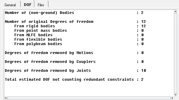
Ideally, after you have selected the perfect joint for Joint C to reproduce the desired motion, what will be the final DOF of this system? also, validate with calculations
Question 2
After selecting joint C, simulate the following mechanism with initial angular velocity at the joint in P0 as 0.5 rad/sec (for mass and inertial properties obtain from associated geometry)
Now, plot a graph for velocity vs time on Joint C or Point P2 w.r.t the ground
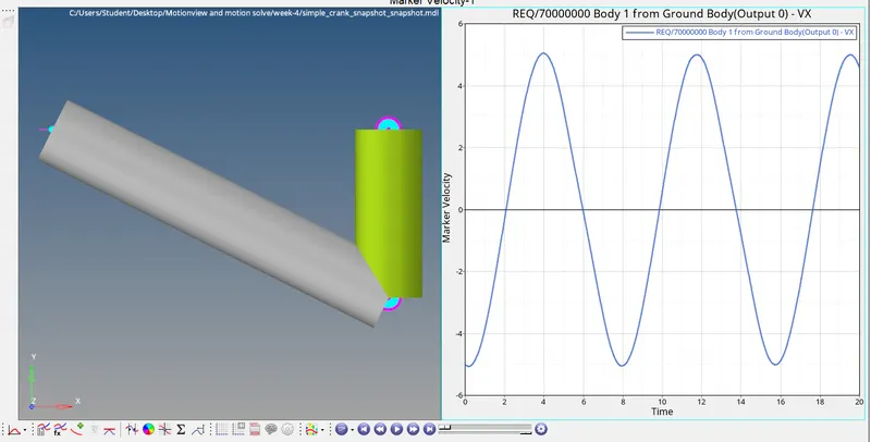
Maximum velocity of Point P2 w.r.t the ground = 5.035m/s at 0.059 sec

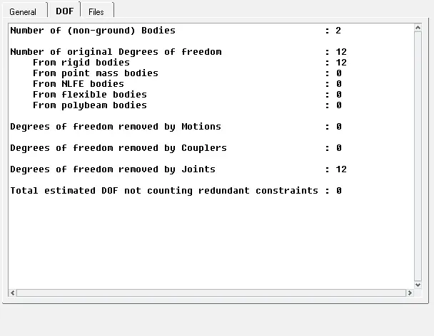
What is the DOF of the system now and why?
DOF will be the 0, since the angular velocity is given as input.
Question 3
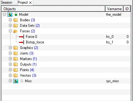
Now, suppress the initial angular velocity, and apply a load of 1000 KN on P1 and simulate and answer the following questions
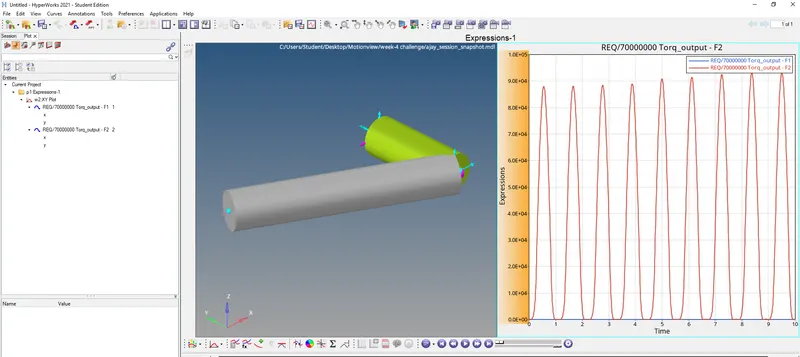
Now, plot a graph for the reaction torque vs time at P0 and explain your results
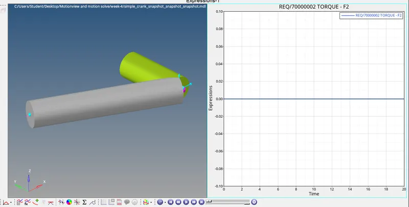
No torque at pt 0.
Compare the range of motion of the crank mechanism between this case and the previous case and explain the reason for the difference if any
In the previous case, velocity is given as input and hence we van able to rotate the crank for a complete rotation and check the output, but the force input 1000KN is provides comparatively less motion.
Question 4
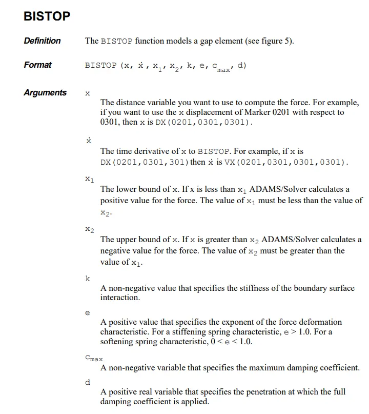
Now, in the same case as Question 3 create a BISTOP function at point P0 with range (-10,0) degrees
Now, again, plot a graph for the reaction torque vs time at P0 and explain your results
`BISTOP(AZ({j_0.joint_i.idstring},{j_0.joint_j.idstring}),WZ({j_0.joint_i.idstring},{j_0.joint_j.idstring}),-10*PI/180,0*PI/180,1e4,2,100,0.1)`
A screenshot of the entire interface must be attached with the plot for all the simulated cases.