Week - 4 - Crash Box Simulation
AIM:-
To perform Impact analysis on the Crash box and view its deformation with different properties and Thickness.
PROCEDURE:
1. Open the Rigidwall_keyword File Given.
2.The File Only Consists of the nodes and elements of the Mobile phone and the table.
3.The Unit system Followed here is gm, mm, ms
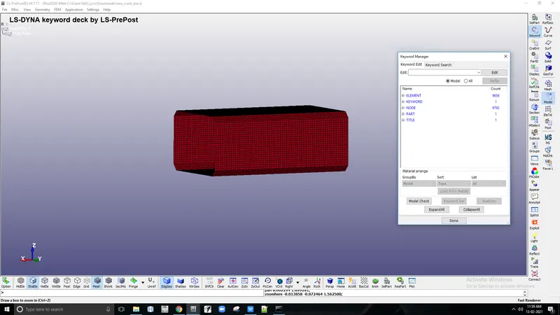
4.To perform the Simulation, materials, Section, initial velocity, Contact Interface, Boundary conditions, Rigid wall Output For the Following Must be Specified.
1.ASSIGNING MATERIALS:-
For Defining materials go to Keyword Manager > All> MAT > Select the Material card and define the material properties like mass density, Young’s modulus, Poisson’s ration, Yield point stress value, and other required quantities for both the material cards. For the Box, The Material card M_20-Piecewise_Linear_plasticity is Assigned with the Properties of Steel.
Massdensity(RO)=0.00785gm/`mm^3`
Young'sModus(E)=2.1e5gm/`mm*ms^2`
Poisson'sratio(PR)=0.3
Yieldstress(SIGY)=310gm/`(mm*ms)^2`
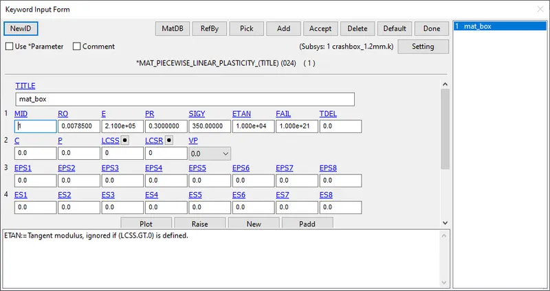
apart from the Properties, all other values are set to default.
2.SECTION CREATION:-
1. For Defining Section Go to Keyword manager > All > Section > Shell
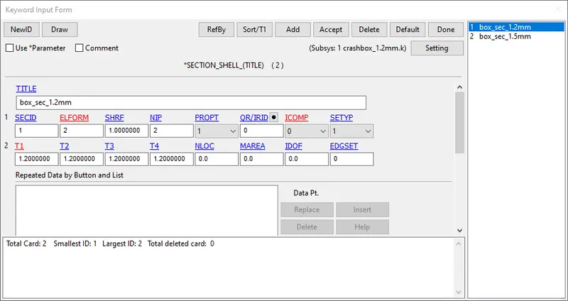
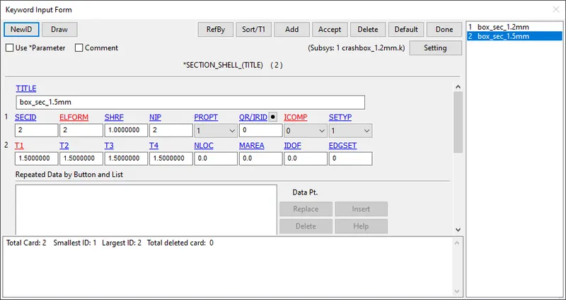
2. For the crash_box Two sections SHELL are created and Thickness is assigned as 1.2mm and 1.5mm respectively.
3.The element formulation is Given as 2.
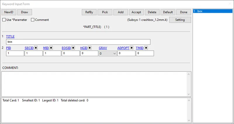
3.Specifying the Material and Section ID to the respective part IDs.
1. In parts, we basically assign material and sections with their proper ID for every part individually.
2.Assign the Section-Id and Materials Individually as Part-1.
3. For Creating part Go to Keyword manager> Model > Part and assign the Materials and Sections of the Crash box.
4.RIGID WALL CREATION:-
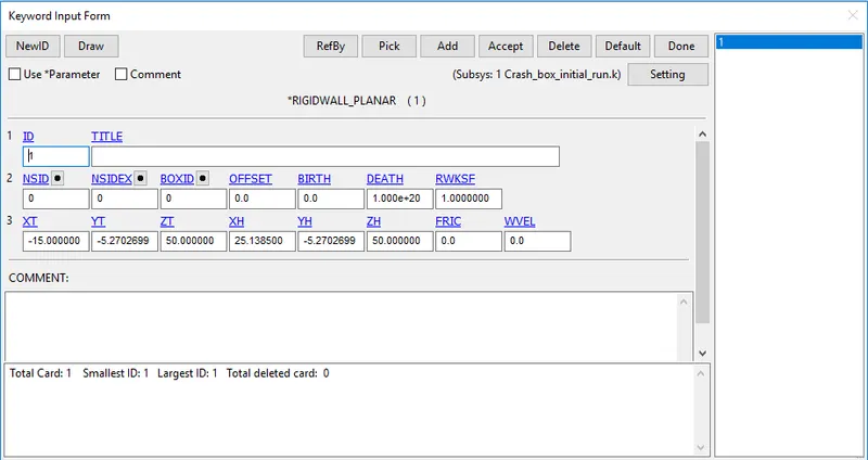
1. As for the impact a Rigid wall is created in normal to the Crash box.
2. For Creating a Rigid wall, go to Create entity > Rigid wall > planar > 1n+Nl > Pick a node and Apply.
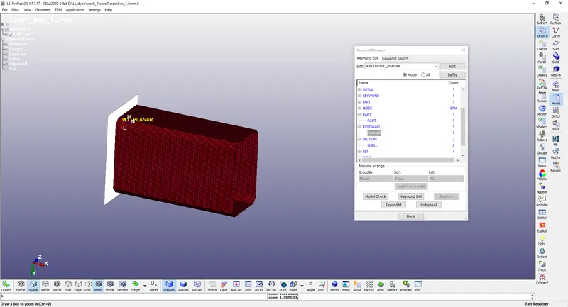
3. The rigid wall is Placed in a position according to the Timestep and output needed.
6.INITIAL VELOCITY:-
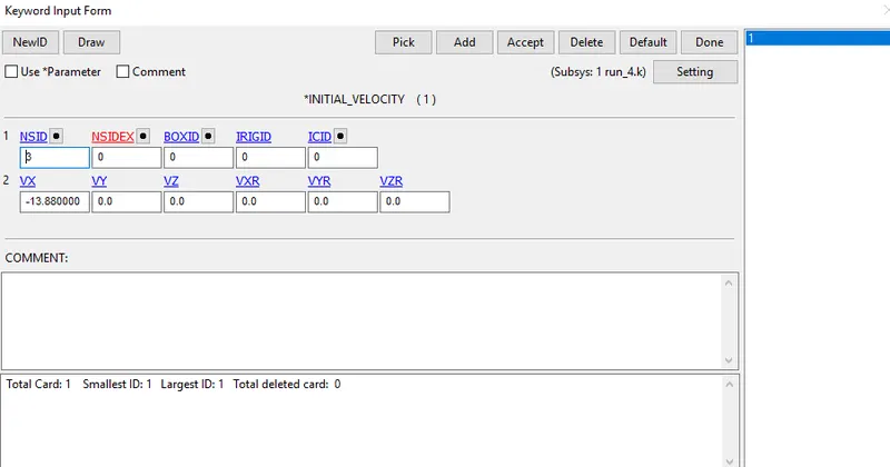
1.Initial velocity Is defined to the Phone By Keyword manager > New > Initial > Velocity. select the Nodes By part Apply
2.An velocity of 13.889mm/s (5okmph) Is assigned to all the Nodes in the Part In the Crash Box.
7.CONTACT INTERFACE:-
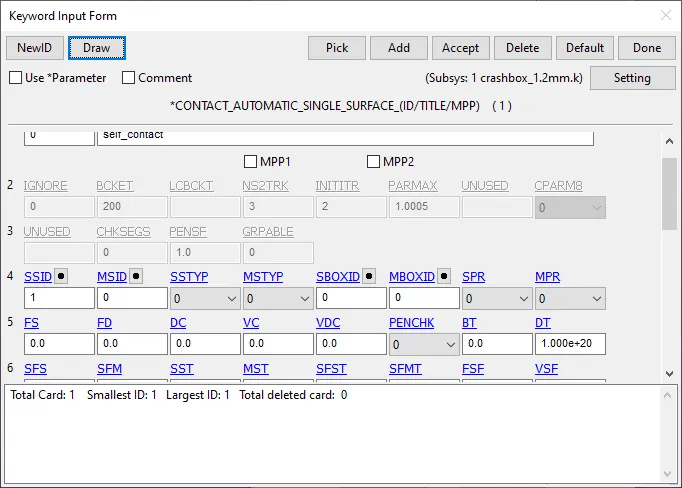
1.As the wall Created is Rigid Here, it acts as Master in Nature, So Automatic Single surface Contact is created defining Crash box as a slave.
2. The slave segment type (SSTYP) is defined by the Part IDs, select the crash box as Slave.
3.All other Parameters are given as default
8. Cross-sectional Nodes:
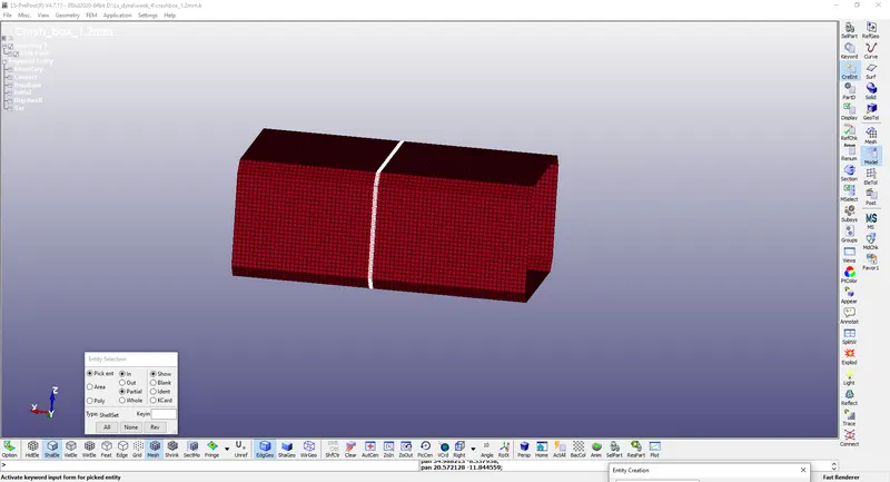
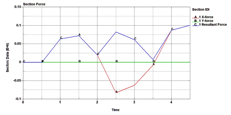
In this analysis, we need the stress, strain, acceleration, and energy values at nodes, sections, and over the whole body. For generating section forces, creating a specific node list and element list which defines the desired section is necessary. Mode list and element list can be created by the 'create entity' option and selecting the required nodes and elements.
9.Control cards:-
1. Control cards such as Control Termination, Control energy are specified.
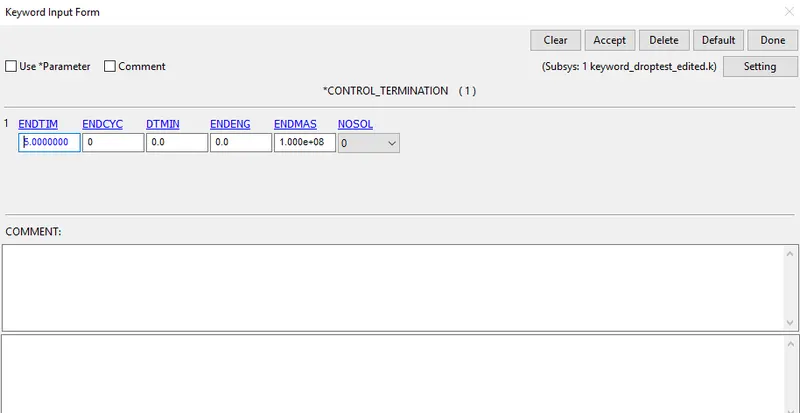
2.Termination time defined by using *CONTROL_TERMINATION card
3.Set Model and Part > Keyword Manager >Control> Termination to 5ms
Control-Energy:
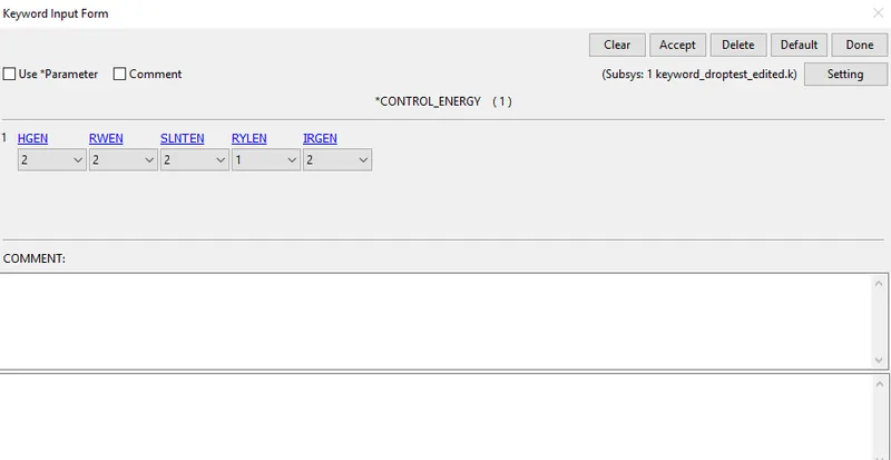
1. control energy is defined to control Hourglass energy occurs during the Simulation
Model and Part > Keyword Manager >Control> Energy and give the appropriate parameters.
10.OUTPUT REQUEST:
1. To view the results of Simulations Following Steps are Specified.
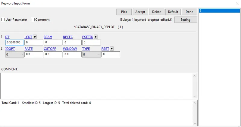
2.The time interval between the outputs is 0.05 is defined in D3plot
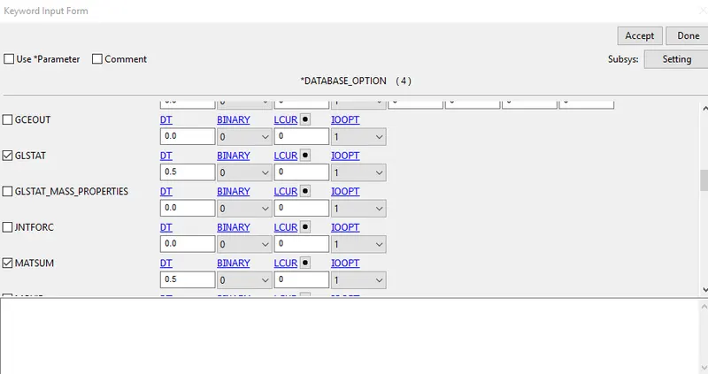
3. Go to Keyword Manager > Database > ASCII select GLSTAT, RCFORC with DT 0.05
4. ELOUT, MATSUM, GLSTAT, RCFORC, RWFORC, SWFORC, NOD OUT this required option assigned into the ASCII option.
MODEL CHECK
11.Run The Simulation.
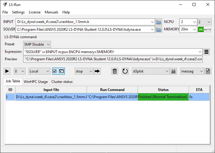
Save the edited keyword in a separate folder and Run the Simulation in LS Dyna Manager.
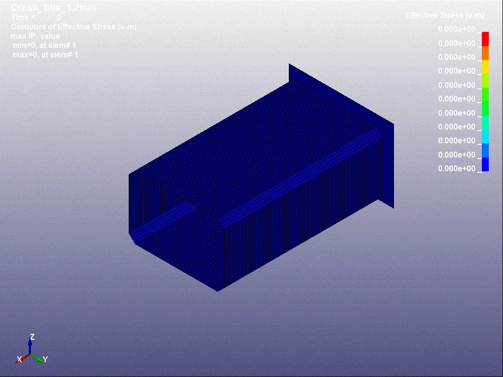
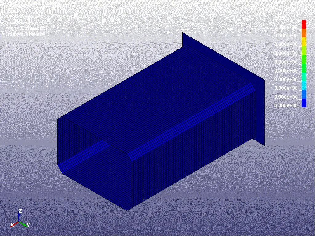
EFFECTIVE STRESS
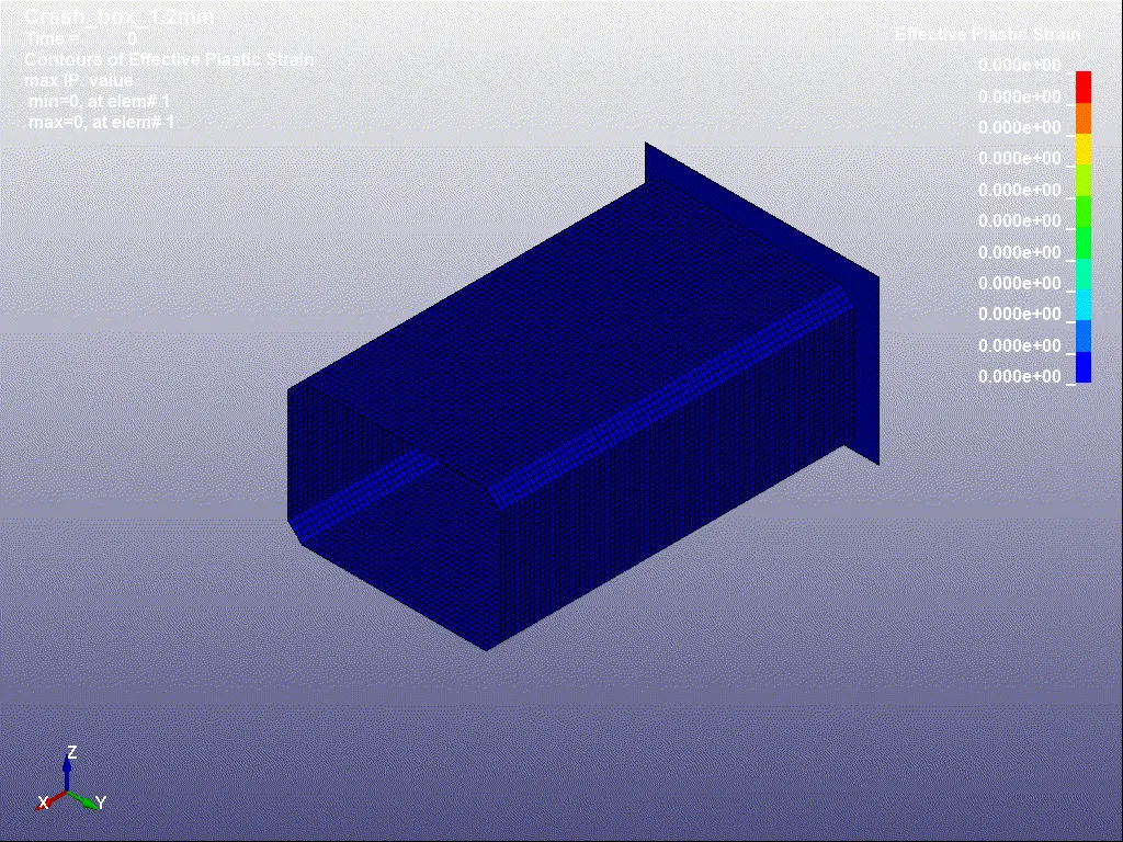
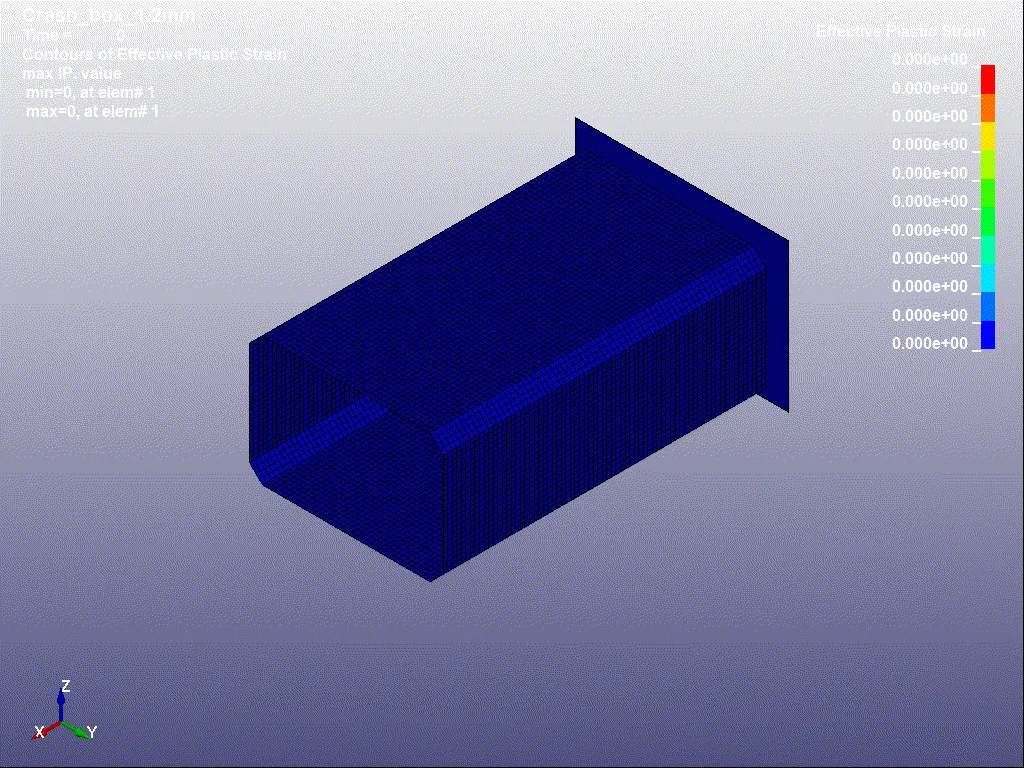
 EFFECTIVE STRAIN
Graphs:-
1.Energy graph:-
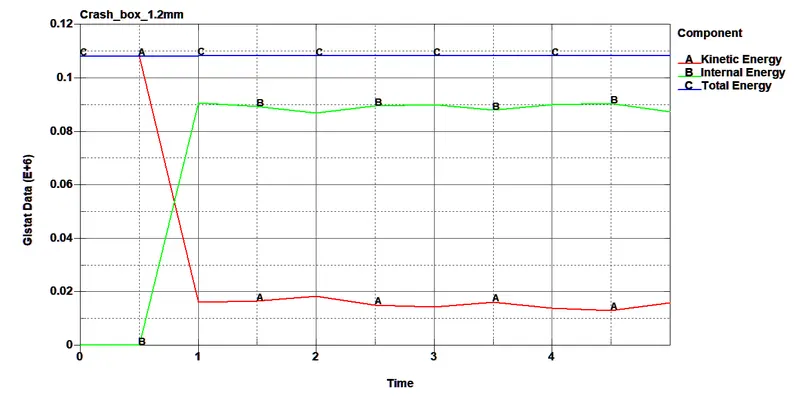
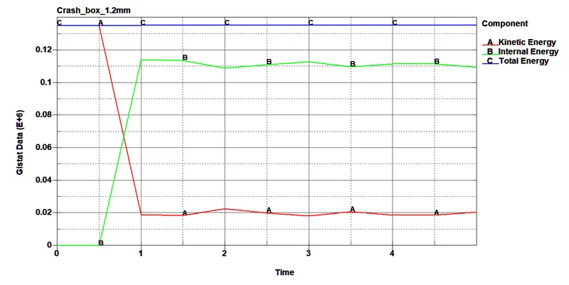
From The graph, we can see that Total energy Is In a straight line as it satisfies the Law of Conservation of energy, as the Internal Energy produced from the wall is equal to the Kinetic energy.
The Kinetic energy Starts is constant till 0.5ms And after the impact decreasing Gradually.
Similarly, the Internal energy rises at the same moment when the impact has happened
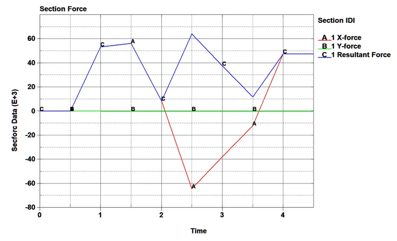
2.Cross-sectional Forces:-
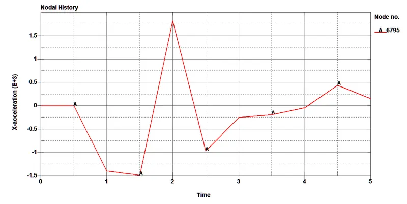
3.Nodal acceleration force:-
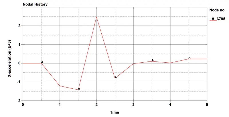
A Random Node is selected in the Middle and its acceleration force was Plotted after the Impact.
EFFECTIVE STRESS
 EFFECTIVE STRAIN
Graphs:-
1.Energy graph:-
From The graph, we can see that Total energy Is In a straight line as it satisfies the Law of Conservation of energy, as the Internal Energy produced from the wall is equal to the Kinetic energy.
The Kinetic energy Starts is constant till 0.5ms And after the impact decreasing Gradually.
Similarly, the Internal energy rises at the same moment when the impact has happened
2.Cross-sectional Forces:-
3.Nodal acceleration force:-
A Random Node is selected in the Middle and its acceleration force was Plotted after the Impact.
Comparison with Thickness:-
| S.No | Required parameter | 1.2mm thickness | 1.5mm thickness |
| 1 | Stress | 324.028mpa | 334.068mpa |
| 2 | Strain | 0.0186 | 0.00838 |
| 3 | Acceleration at 6795 | 2.5`e^03` at 2ms | 2.`e^03` at 2ms |