Week - 4 - crash box simulation
OBJECTIVE:
Perform impact analysis on a crush tube to understand how it works and how much the thickness of the tube affects the results.
DETAILED PROBLEM STATEMENT:
- The crash box should crash into a rigid wall
- The material for the crash box is steel (nonlinear ). The thickness of the crash box is case-a:1.2mm and case-b:1.5 mm
- Initial velocity for the crash box should be around 50 kmph
- The units system to be used is gm-mm-ms
- The simulation should satisfy either of the two situations - (1) It crashes on the rigid wall and rebounds completely or (2) it buckles and folds in the axial direction so as to come in self-contact.
- Compare the results for increasing the thickness of the crash box from 1.2 to 1.5mm.
- Input .k file and output files (glstat, sleout, rcforc)
- Animation of the final simulation
- The cross-sectional force generated in the middle of the crash box (along its length)
- Acceleration plot of a node in the middle of the crash box (along its length)
- Maximum directional stress and strain along the length of the crash box (X strain, Y strain, etc)
- plots of all energies (total, internal, kinetic, hourglass, sliding)
PROCEDURE:
The project requires nonlinear material for analysis. But preliminary analysis is carried out with elastic material and all necessary boundary, loads, and output requests. Then the material is changed to nonlinear in subsequent analysis.
1.Given model:
our crash box model has 1 meshed part as shown.
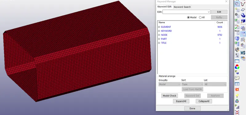
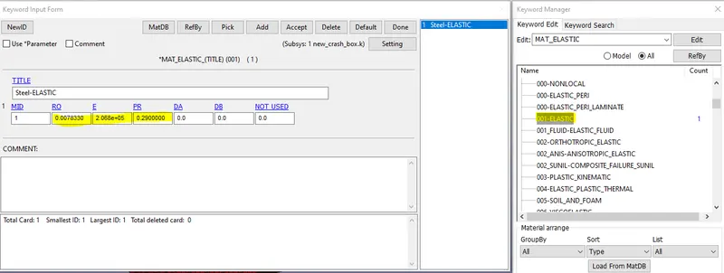
2.define the material for the crash box: define elastic material for preliminary analysis also define a non-linear material
a. ELASTIC material for preliminary analysis
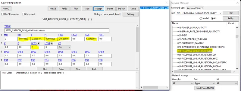
b. Non-linear material (024-PIECEWISE_LINEAR_PLASTICITY)
define a curve for the plastic region as shown using define->curve option
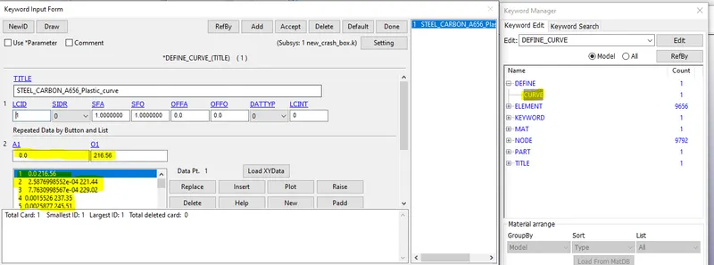
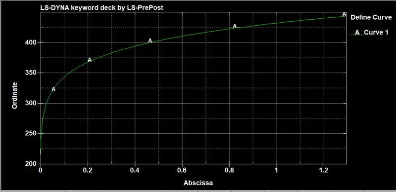
define material and load the curve:
enter density, young's modulus, Poisson ratio, yield then load the plastic curve data in LCSS
3.SECTION: shell
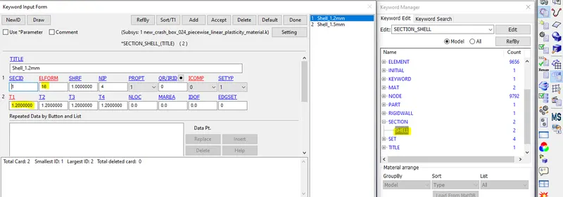
create a shell section with elform=16 (fully integrated). and NIP as 4 to have 4 elements in the thickness, and T1 as 1.2 mm for the thickness of the crash box.
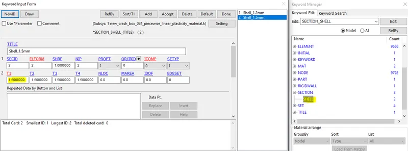
similarly, create another section with 1.5 mm thickness
4. assign material and section to part
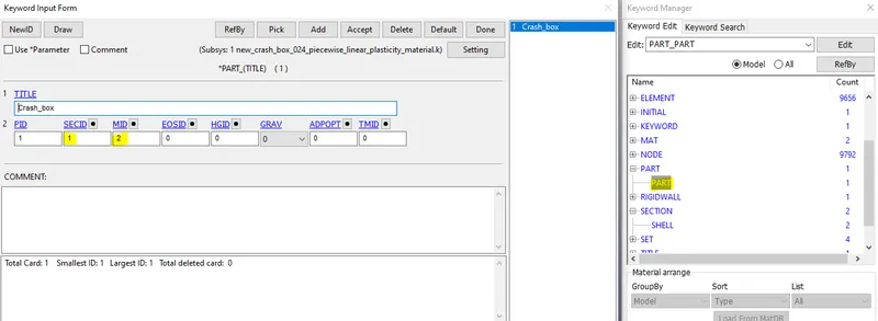
enter the section Id in SECID and material id in MID as follows for the analysis
| SECID | MID | |
| preliminary analysis( to check the model) | 1 (thickness=1.2mm) | 1 (001-MAT-elastic) |
| Case-a | 1 (thickness=1.2mm) | 2 (024-MAT-piecewise linear plasticity) |
| Case-b | 2 (thickness=1.5mm) | 2 |
5.RIGID WALL: The next step is to create a Rigid wall in front of the crash box 10 mm away by using the *RIGIDWALL_PLANAR card
This is done by selecting Entity Creation > RigidWall > Create. The rigid wall type is selected as a Planar and defined vector with one point and a normal ie, 1n+NL here selected the one node, and the normal is created as a rigid wall. This rigid wall is translated/offset by 10mm from the crash box component.
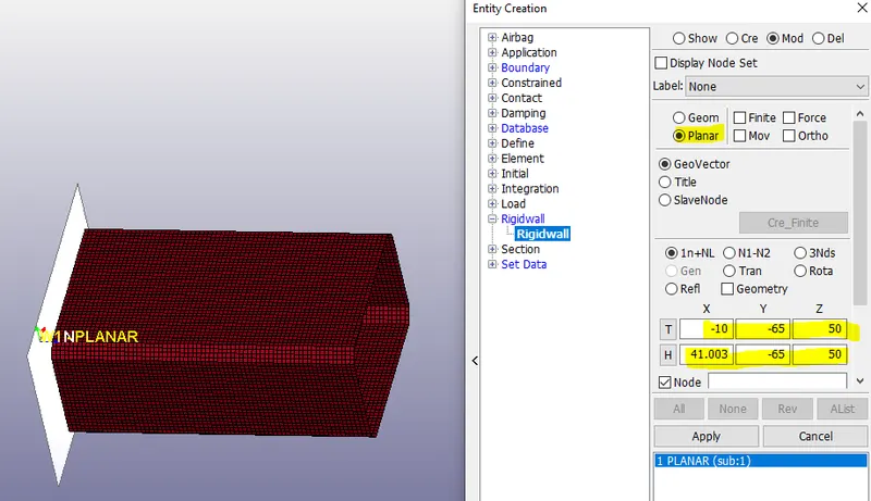
Note: The direction of normal (here x-direction) from the rigid wall and the velocity vector (x-direction) should be in the opposite direction in order to avoid the penetration of the crash box through the rigid wall which is not acceptable since it is a rigid wall and the component is a material which shows the plasticity.
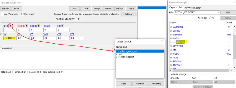
6.INITIAL_VELOCITY: create a node-set with all nodes of the crash box, then assign the node-set to the initial velocity card and enter the velocity as -13.889mm/ms in negative x-direction as shown
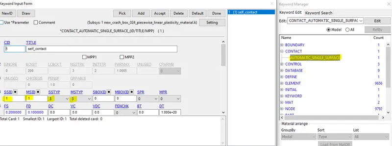
7.CONTACT: create an automatic single surface contact with crash box both as master and slave
8.CONTROL:
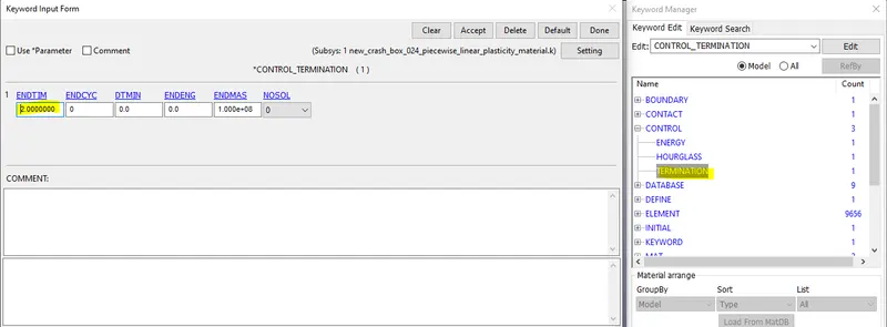
create a termination card with the end time as 2ms
calculate the energy dissipation, Hourglass energy, rigid wall energy, sliding interface energy that can be done by *CONTROL_ENERGY card.
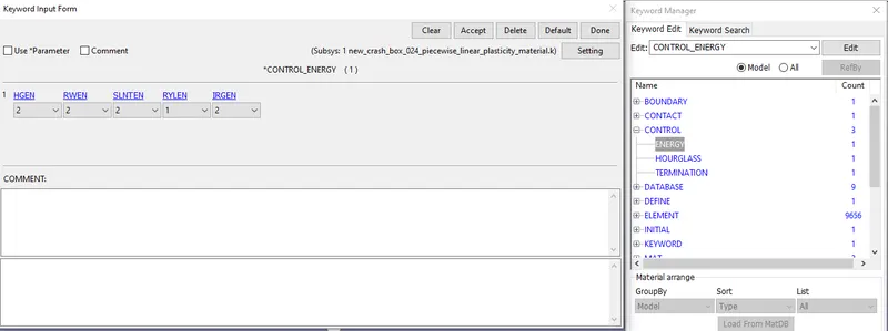
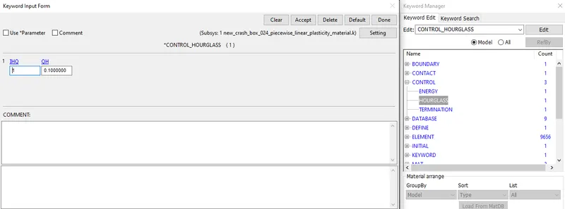
Also create a *CONTROL_HOURGLASS card for the control hourglass effect in the analysis with 1HQ=2, QH=0.1.
9.DATABASE:
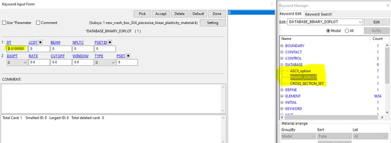
Now, the following output data is generated by using the *DATABASE card with dt of 0.01ms that are assigned for generating output data.
DATABASE_BINARY_D3PLOT --> Used to find out the animation of the process,
DATABASE_ASCII_ELOUT --> To find the element data,
DATABASE_ASCII_GLSTAT --> To find the global statistics and energies,
DATABASE_ASCII_RCFORC --> To find the Resultant contact interface forces,
DATABASE_ASCII_SLEOUT --> To find the Contact interface energies
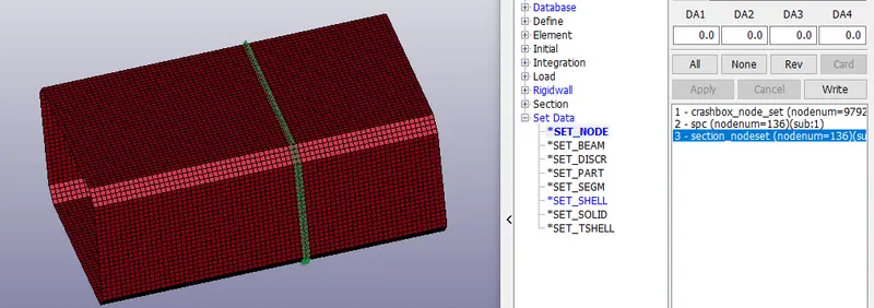
*DATABASE_CROSS_SECTION_SET card is used to find section forces. node-set ID (NSID) and shell element set ID (SSID) are created for cross-section
--------------------------------------------------------------------------------------------------------------------------------------------
RESULTS:
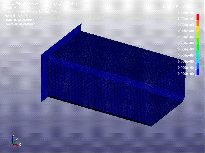
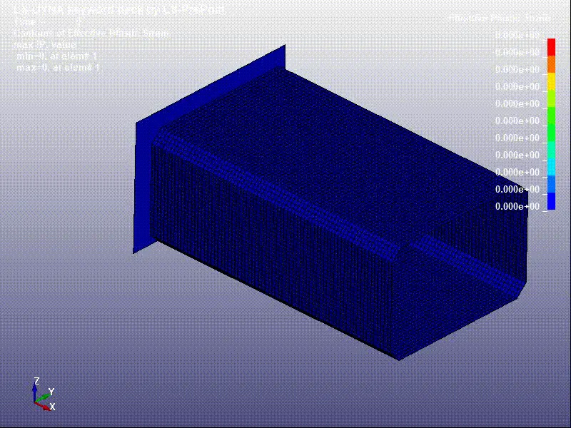
Effective plastic strain for case-a(left) and case-b(right)
Z-displacement for case-a(left) and case-b(right)
Y-displacement for case-a(left) and case-b(right)
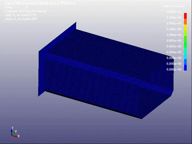
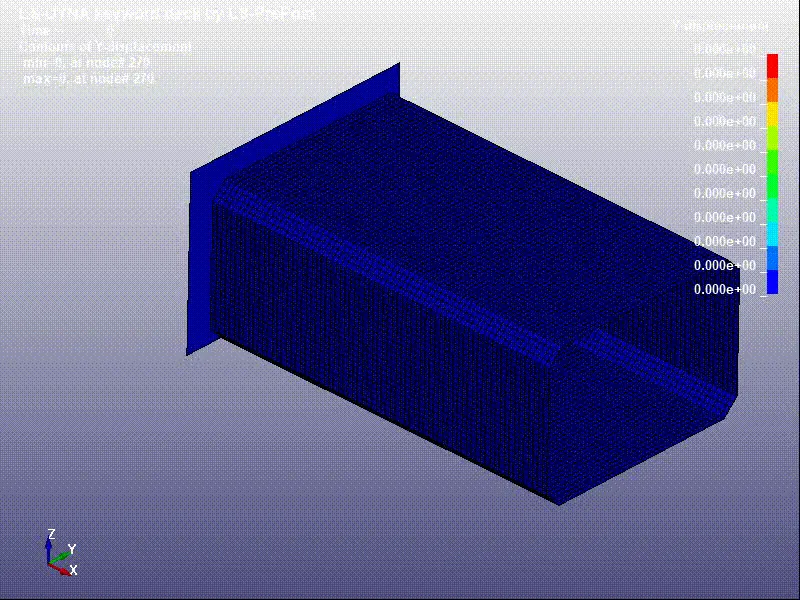
Only the fornt part of the crash box experiences plastic deformation but the deformation is very small.
--------------------------------------------------------------------------------------------------------------------------------------------
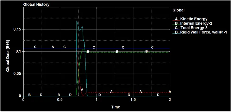
ENERGY plots:
CASE-a:
CASE-b:
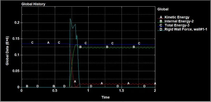
- Kinetic energy of 1.5mm tube is larger than 1.2mm crash box, as a result rigid wall force is also large.
- after impact kinetic energy is greatly reduced while internal energy increases
--------------------------------------------------------------------------------------------------------------------------------------------
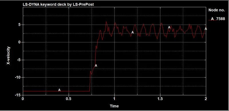
The velocity of a node in the middle of the crash box :
CASE-a: x-direction
CASE-b: x-direction
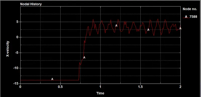
before ipact the velocity of crash box is -13.889mm/ms but after impact the velocity is around 5mm/ms
--------------------------------------------------------------------------------------------------------------------------------------------
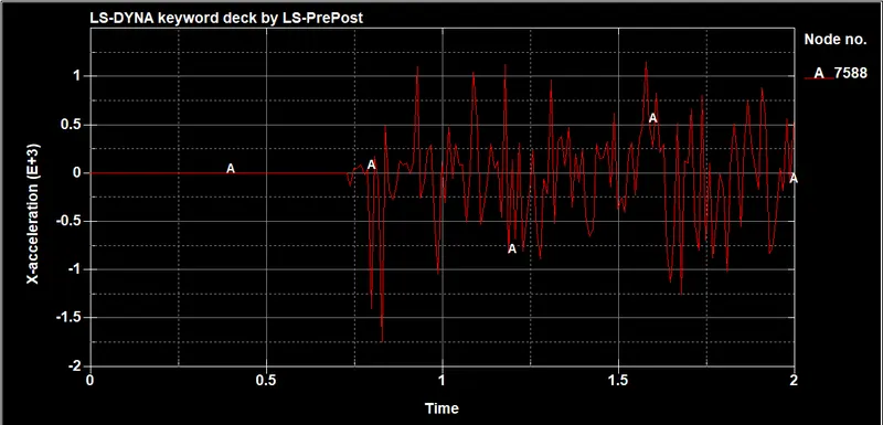
The acceleration of a node in the middle of the crash box :
CASE-a: x-direction
CASE-b: x-direction
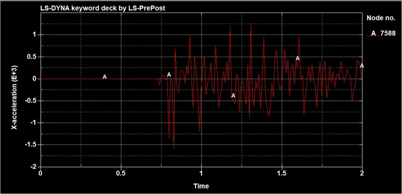
after impact the acceleration of node in the middle of crash box oscillates because of the shock of the impact
--------------------------------------------------------------------------------------------------------------------------------------------
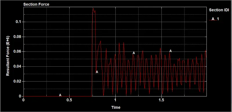
The cross sectional force in the middle of the crash box :
CASE-a:
CASE-b:
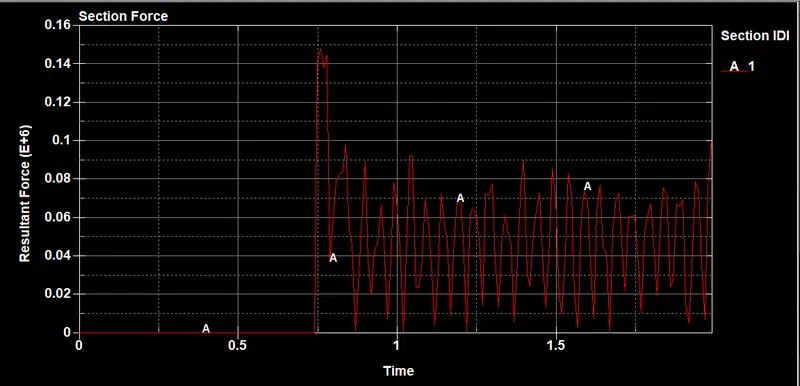
At the impact time, we can see that the force value in X-direction peaks up andgoes down after bounce-back of the crash box.
The Resultant force of a 1.5 mm thickness crash box is higher than that of a 1.2mm thickness crash box since it has more weight
CONCLUSION:
Simulated the crash test for the given crash box having a thickness of 1.2 and 1.5mm onto a rigid wall at 50kmph.
Only the front part of the crash box experience plastic deformation
The crash box bounces back after impacting on the rigid wall and doesn't experience any buckling folds due to low initial velocity and KE energy is used by the box to bounce back.