Bumper Crash Box Simulation Using LS-Dyna explicit Solver
AIM: To simulate the crash box behavior impact on a Rigid wall
ABSTRACT: In this project, we have taken a crash box thin-walled section of a bumper that undergoes a very large energy absorption, avoiding energy to travel to other components and ultimately saves the occupant. Here we will give a speed of 50kmph to the crash-box towards the rigid wall and will try to simulate the results. There can be either of the two situations 1) rebound back or 2) box crushes and folds.
Also, we are going to compare the results for the box wall thickness for 1.2 and 1.5 mm and plot the stress, strain, and acceleration plots.
THEORY:
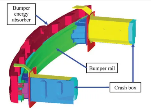
These crash boxes are equipped at the front end just behind the front rail (as shown in the figure below). They are the most important automotive part of crash energy absorption. in case of a frontal crash accident, these boxes are expected to collapse with absorbing crash energy prior to any other part so that the damage of the main cabin frame is minimized and passengers are saved. so the pre-analysis and design optimization of these boxes are very important.
METHODOLOGY: We need to follow these few steps in order to get the correct results.
- Open the keyword file into LS- Prepost
- Create a Rigid wall
- Assign material, section, and part card to the crash box
- Assign contact card
- Provide initial velocity of 50kmph or 13.889mm/ms to the box towards wall
- Create the database card D3PLOT, ASCII, SECTION, NODE_HISTORY....etc
- Set CONTROL Termination card and tile
- Save the keyword file and run the LS-dyna solver
- run the binary file (D3PLOT) to see the required results.
PROCEDURE:
The unit system followed is the gram, millisecond, millimeter [gm,ms,mm]
Open the keyword file into LS- Pre post
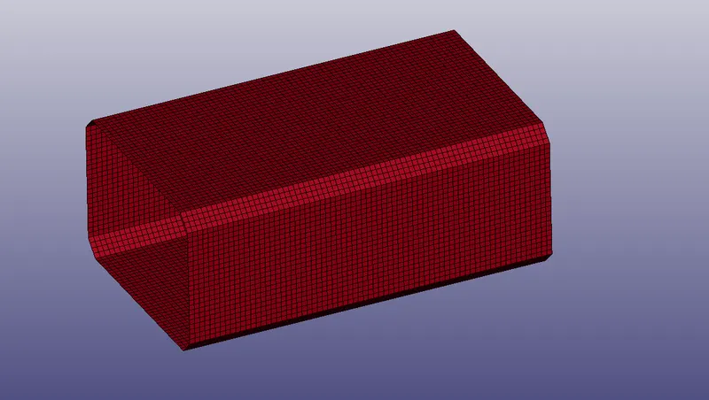
When we open the keyword file we get this box/channel in the graphics window. This is the portion of the bumper called the crash box.
Create a Rigid wall
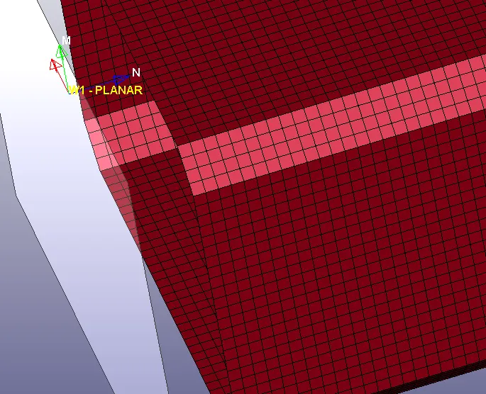
To simulate the crash behavior of the box we need to create a rigid wall. this can be done in two ways either using MAT_20 rigid material for shell plate which is not present in the model given or by creating a rigid wall directly using create an entity Rigidwall(as shown below).
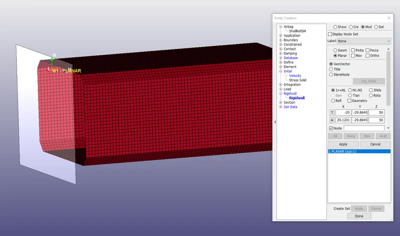
select the planer type wall and give the tail and head node which will decide the wall's normal direction(Blue Arrow). This is supposed to be in the opposite direction to the velocity vector direction. ( if need to adjust the normal angle select roto>scroll down to provide angle). select apply and done. The transparent glass sort of in front of the box is the rigid wall.
Assign material, section, and part card to the crash box
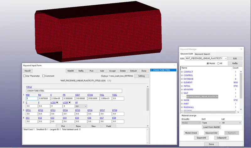
Now we need to assign the material card, section, and part for the crash box for steel.
steel properties in [gm,ms,mm] unit system
Density(RO): 0.00785 gm/mm3
Young Modulus(E): 210000 gm/mmms2
Poison ratio(PR): 0.3
Yield Strength(SIGY): 310 gm/mmms2 (steel grade 3 A253)
Tangent Modulus (ETAN): 21000 gm/mmms2 (should be less than young modulus) [SHOULD BE ENTERED IN LCSS IS NOT DEFINED]
we will use a PIECEWISE_LINEAR_PLASTICITY_CARD and steel properties are been defined.
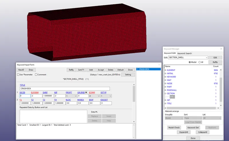
similarly, now we will define the section with wall thickness as 1.2mm with Element formulation as 2 (default) and number of integration point default as 2
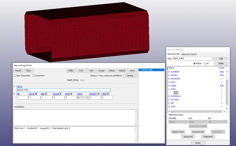
Now we need to assign the section and material to the part as shown below
Assign contact card
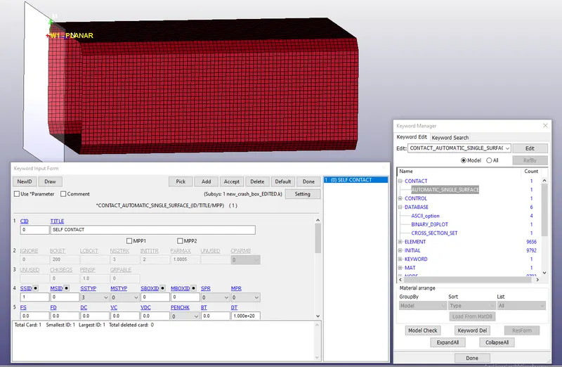
The contact card defined here is AUTOMATIC_SINGLE_SURFACE for self contact where SSTYP is set as 3(by part) and MSTYP as 0 (need not to define for self contact) and slave as the crash box and no need to define master. The automatic algorithm will self decide the slave and master depending upon the stiffness.
Provide an initial velocity of 50kmph or 13.889mm/ms to the box towards the wall
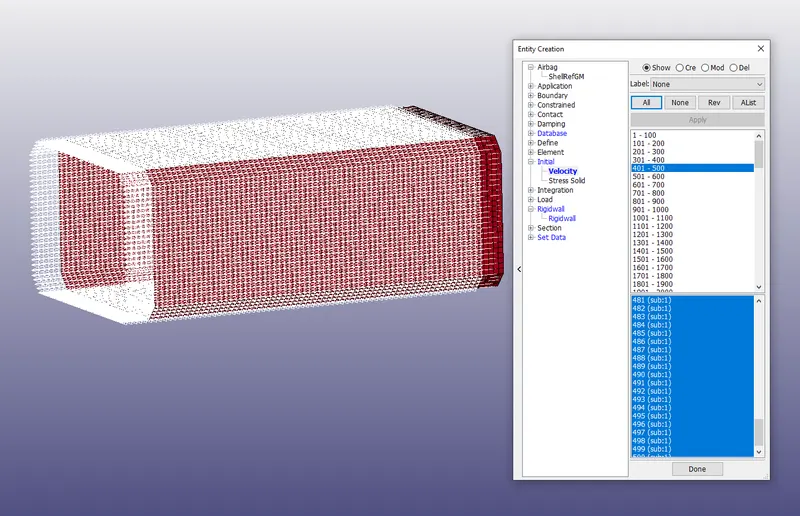
We need to define the initial velocity in x-direction towards the wall as 13.889 mm/ms. to do so we have to create a new entity(SET_NODE )and select by part the complete crash box (each node).
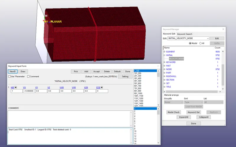
Goto keyword manager and assign the value of Vx at -13.9 mm/ms (negative sign for the opposite to the global x-direction)
Cross-sectional details
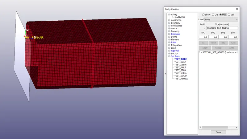
We have to define the set of nodes for cross-section details. os first we need to define the set of nodes at the middle section along its length of the box as shown in the figure below
Shell set for the section force
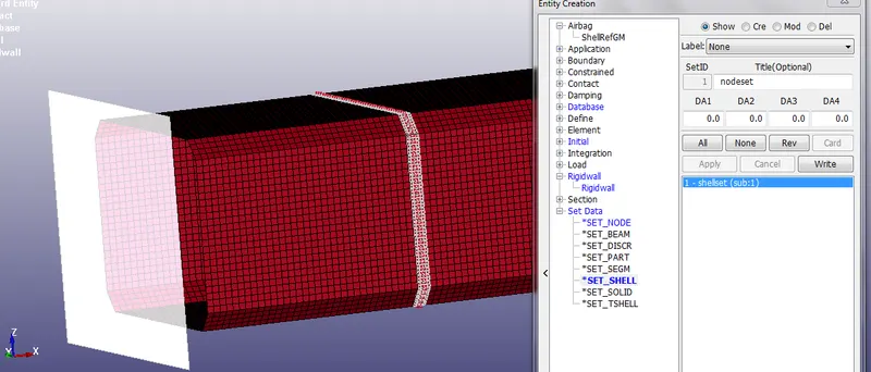
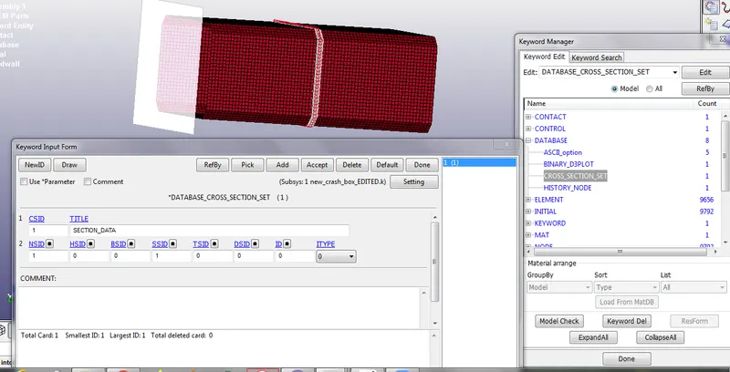
Now we will define the under keyword manager the Database CROSS_SECTION_SET and in that link, the node-set id for the middle section node-set created earlier. this is done to get the Section force. also set the shell set to the SSID.
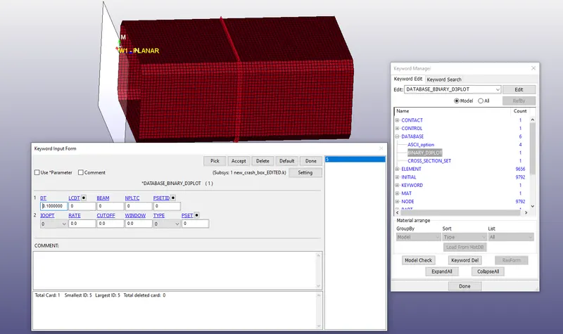
Create the database card D3PLOT, ASCII, NODE_HISTORY....etc
define the D3PLOT for getting the binary output file and ASCII for GLSAT(global states), MATSUM (material energy plots), ELOUT(energy plots), SLEOUT(contact interface energy), RCFORC (resultant contact forces)
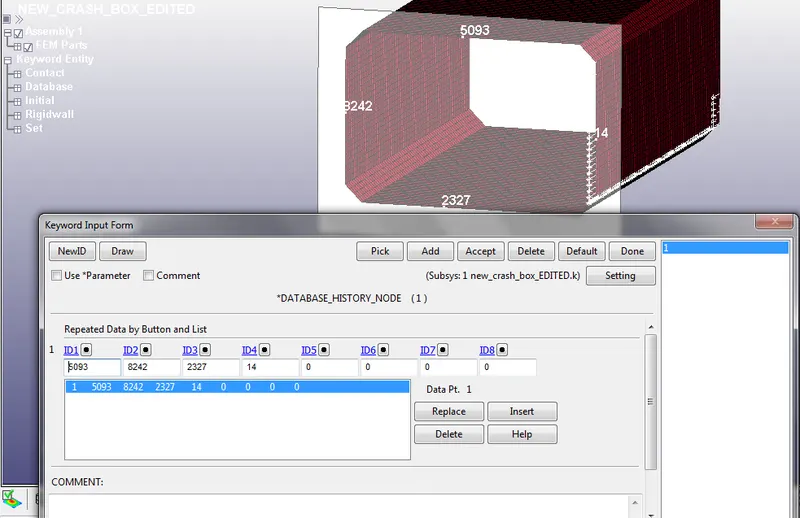
DATABASE_HISTORY_NODE CARD FOR NODAL INFORMATION ABOUT ACCELERATION AT XYZ DIRECTION AND RESULTANT.
Set CONTROL Termination card and tile
To set the termination card we to set the ENDTIME in such a way that box impacts the rigid wall and some more time to set the after effect.
time =distance/ speed= (20mm)/(13.9mm/ms)= 1.4388 ms~1.5ms
we will keep an extra 0.5 ms to see the after impact effect. Therefore, ENDTIME = 2 ms
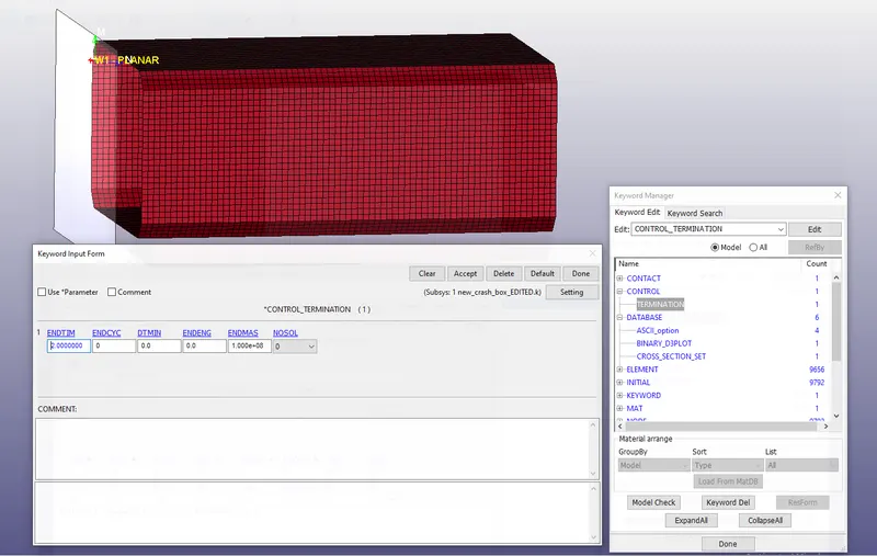
Save the Keyword file in a folder and run the file in the LS Run to solve the file. Open the binary file in the LS pre post to analyze the results.
CONCLUSION:
Cross-section Forces
1) For 1.2 mm wall thickness
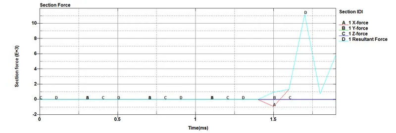
As you can see in the plot which shows the section force created in the middle of the box along the length. The max value for the resultant force is nearly 11.2E+03 (gm.mm/ms2)
2) For 1.5 mm wall thickness
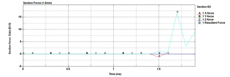
As you can see in the plot which shows the section force created in the middle of the box along the length. The max value for the resultant force is nearly 16.7E+03 (gm.mm/ms2)
In both, the case of the Y & Z-direction force is nearly zero as the velocity is in the X-direction. The value of force in 1.5mm wall thickness is a bit high as compared to the 1.2 mm thickness wall for the crash box and this due to the increased inertia effect with the increased thickness.
From the start of the simulation until the impact the graph is flat constant at zero but and nearly 1.5 ms the force starts increasing touches the peak value then drops down.
Acceleration plot
1) For 1.2 mm wall thickness
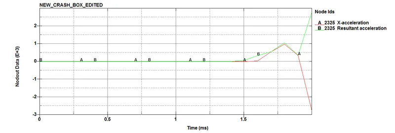
The above plot shows the nodal acceleration wrt time for the 1.2mm thickness wall crash box for Node no. 2325 (X direction and resultant)
2) For 1.5 mm wall thickness
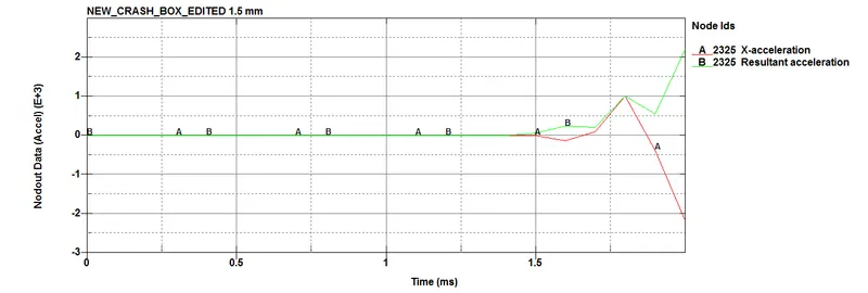
The above plot shows the nodal acceleration wrt time for the 1.5mm thickness wall crash box for Node no. 2325 (X direction and resultant)
As we can see both the plot shows much similar plotting pattern for the node 2325 but the acceleration at the end of the simulation 2ms for 1.2mm thick box is a bit high. The red graph for X acceleration becomes negative after the impact of i.e deacceleration.
Energy plots
1) For 1.2 mm wall thickness
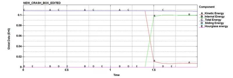
The above plot shows the energy plots KE, I.E, T.E, S.E, H.E for the 1.2 mm thick wall of the crash box
2) For 1.5 mm wall thickness
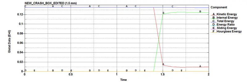
The above plot shows the energy plots KE, I.E, T.E, S.E, H.E for the 1.5 mm thick wall of the crash box
Both cases show a very similar pattern, but the total energy for the 1.5 mm thickness is a bit more than the 1.2 mm thick wall as the added mass with thickness. The kinetic energy is constant until impact then the K.E is converted to Internal energy and I.E(strain energy) increase and K.E reduces. The hourglass energy is zero for both cases.
Stress and Strain Plots
1) For 1.2 mm wall thickness
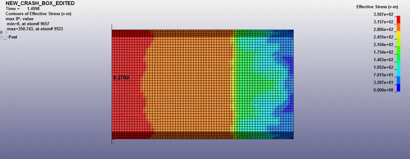
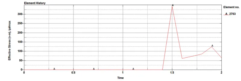
Effective stress plot
Effective strain plot
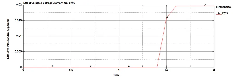
As we can see from the above plot of the effective stress and strain. the maximum value of stress under the von-mises criterion is 350 Mpa and effective strain nearly 0.02 units.
2) For 1.5 mm wall thickness
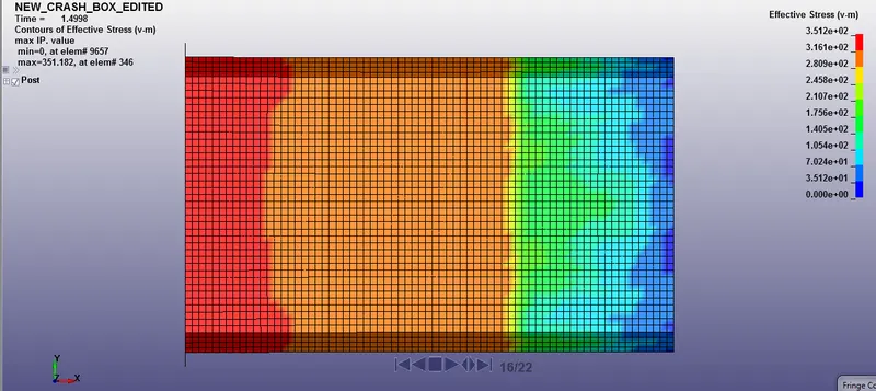
Effective stress plot
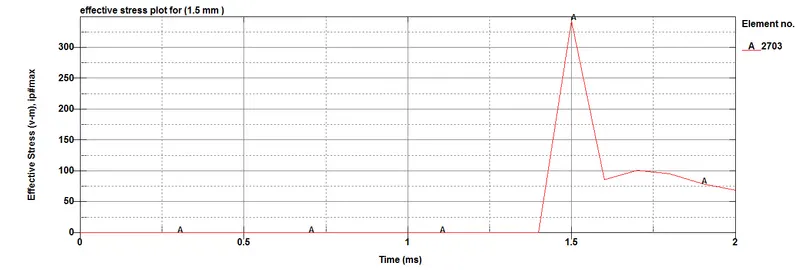
Effective strain plot
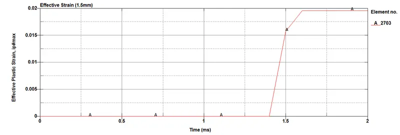
As we can see from the above plot of the effective stress and strain. the maximum value of stress under the von-mises criterion is 351 Mpa and effective strain nearly 0.02 units. The difference in both cases is very small but both of them have stress values above their yield values.
Crash box with 1.2mm wall thickness impact animation
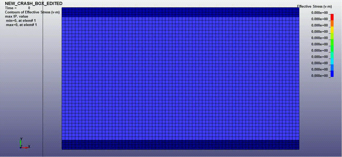
Crash box with 1.5mm wall thickness impact animation