Week - 4 - crash box simulation
Question:
In this assignment, the student needs to simulate a crash test for a crash box for which mesh is given. A crash box is a highly energy absorbing structure that crashes on application of loads and reduces impact on other components nearby. A full-fledges crashbox is a highly sophisticated design but in this case we will go with a rectuangular channel which can thought of as the most simple crashbox.
Here are the different assumptions and information required:
- The crashbox should crash into a rigidwall created using *RIGIDWALL_ keyword. Check the manual to understand and create a rigidwall.
- Material for the crashbox is steel. The simulation needs to be started using elastic material to verify its correctness and later a nonlinear material card data will be provided. Thickness of the crashbox is 1.2mm.
- Initial velocity for the crashbox should be around 50 kmph
- The units system to be used is gm-mm-ms
- The simulation should satisfy either of the two situations - (1) It crashes on the rigidwall and rebounces completely or (2) it buckles and folds in the axial direction so as to come in self-contact.
- Once the simulation is completed and results as asked for below is collected, run another simulation by increasing the thickness of the crashbox from 1.2 to 1.5mm.
Deliverables:
- Input .k file and output files (d3plot, glstat, sleout, rcforc)
- Animation of the final simulation
- Cross-sectional force generated in the middle of the crashbox (along its length)
- Acceleration plot of a node in the middle of the crashbox (along its length)
- Maximum directional stress and strain along the length of the crashbox (X strain, Y strain etc)
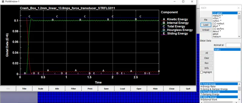
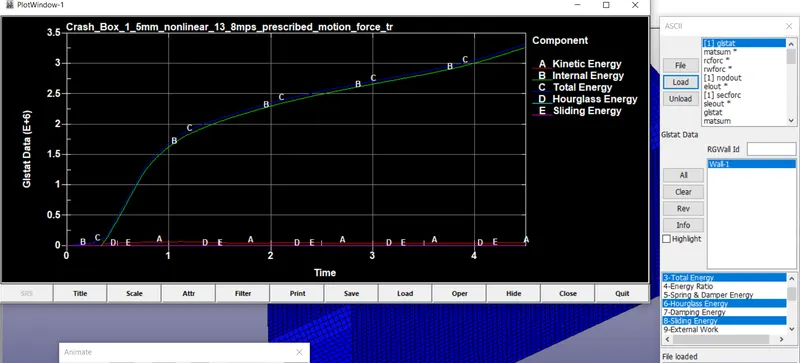
- Plot of all energies (total, internal, kinetic, hourglass, sliding)
- Compare the accelerations and stress/strain plots of 1.2/1.5mm crashboxes.
Objective:
To simulate a crash test for a crash box
Case Setup:
There will be 2 models in the report
- 2mm thickness model (elastic material) running with 50m/s initial velocity with 3ms run time
- 5mm thickness model (nonlinear material properties) with imposed velocity (Using CNRB) 50m/s with 4.5ms run time
The downloaded file contains the following Keywords
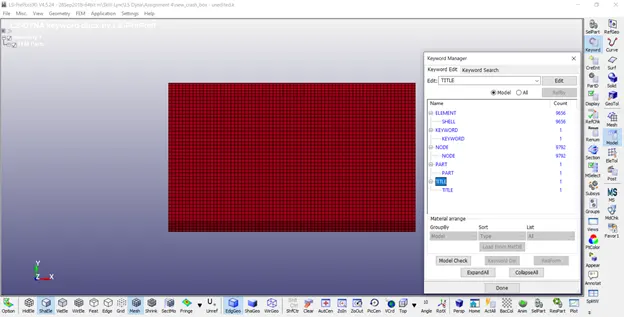
To start with the analysis, we need to create following cards
- Material
- Section
- Hourglass
- Initial velocity
- Rigid wall
- Control Energy
- Control termination
- Contact Automatic Surface to Surface
- Database ASCII (ELEOUT, GLSTAT, MATSUM, SLEOUT)
- Database Binary D3plot
- Set (Node, Part, Solid)
- History
I’m using mm ms gm system of units
Material:
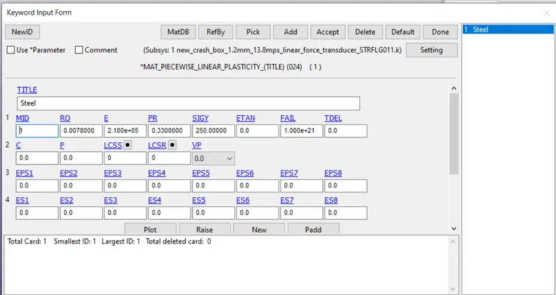
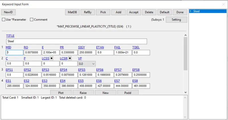
Mat 24 MAT_PIECEWISE_LINEAR_PLASTICITY is used with Steel properties for the Crash box. Elastic material is assigned to 1.2mm thickness model and non linear material is assigned to 1.5mm thickness model(EPS and ES values corresponds to Effective plastic strain and Yield stress value which are used to model non linear properties).
Section:
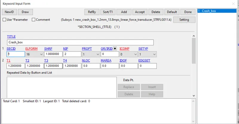
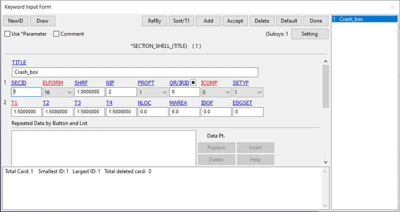
Section_Shell card is used for the ground as it has only 2D mesh with following properties.
Hourglass:
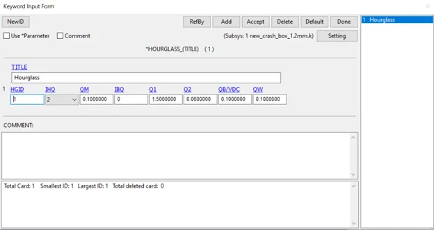
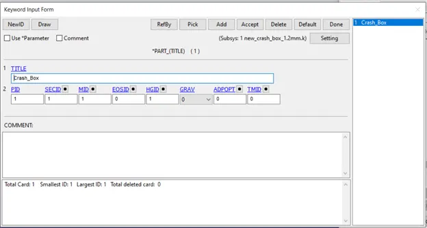
Hourglass card is created with IHQ 2 which uses Flanagan-Belytschko viscous form. This Hourglass setting will be applied as default for all the parts. But to be counted in the energy balance equation, Control Energy is to be used which will be discussed later.
After creating Hourglass card, Part Keyword is opened and assigned corresponding material, section and Hourglass ID.
Initial velocity and Imposed velocity:
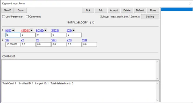
For 1.2mm thickness model, Initial velocity card is created with Vx=13.8mm/ms (corresponds to 50kmph) and a node set is created with all nodes belonging to crash box
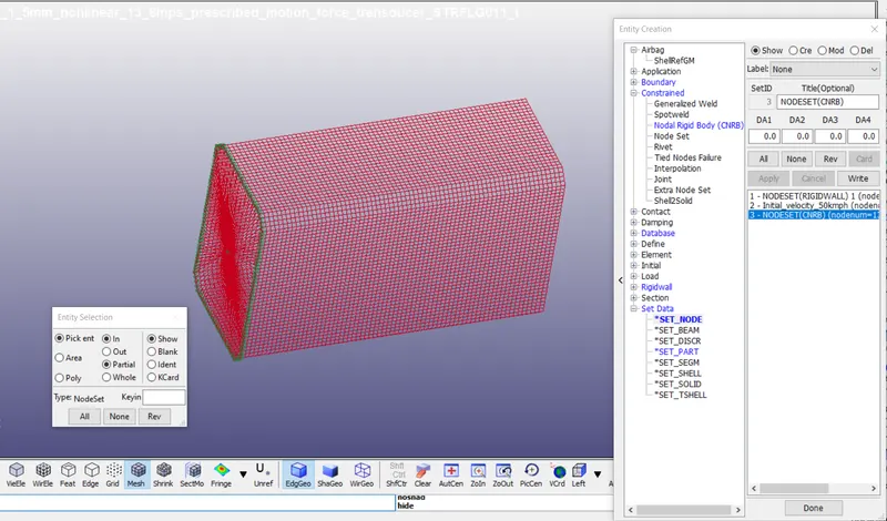
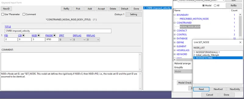
For 1.5mm thickness model, we will create Constrained Nodal Rigid Body with the end nodes. This will create a spider link with an independent node at the center of mass.
Rigid wall planar:
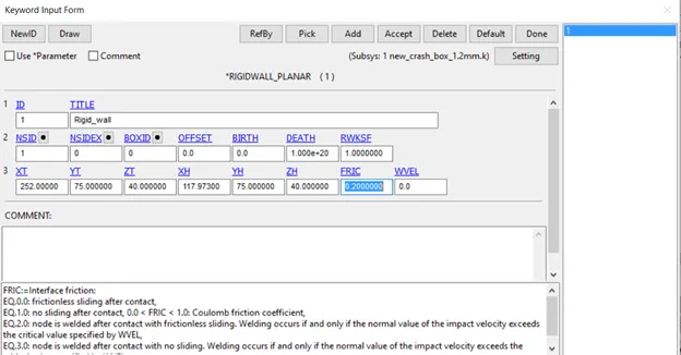
A rigid wall is created using Rigidwall_planar card. Coordinates of Tail and Head of the outward drawn normal vector, originating on wall and terminating in space is specified.
Control Energy:
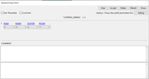
Control Energy card is used with following values. 2 means the energy is computed and taken into account in energy balance equation
Control Termination and Timestep:
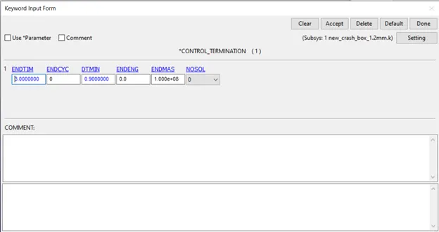
Control Termination tells the solver to stop analysis at a said time (ENDTIM). 1.2mm thickness model is given 3ms ENDTIM
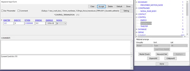
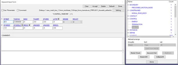
1.5mm thickness model is given 4.5ms ENDTIM and DTMIN is changed to 0.5 from 0.9 default value since this model involves crushing of the crash box. DTMIN is the Reduction (or scale) factor for initial time step size to determine minimum time step.
TSSFAC in CONTROL->TIMESTEP is also changed to 0.9. TSSFA is the Scale factor for computed time step. (Default =0.9. If high explosives are used, the default is lowered to 0.67).
Contact Automatic Surface to Surface:
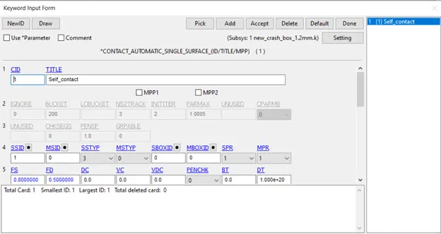
Contact Automatic surface to surface is created with Rigid wall as master and crash box as Slave. SSTYP and MSTYP is changed to 3 which allows to use part as SSID and MSID or 2 which allows part set IDs for which we need to create part sets
Database ASCII:
Database ASCII is used and following outputs are selected with 0.01 DT
SLEOUT: Shows information about Sliding Energy
RCFORC: Resultant Interface force
ELOUT: shows directional stress and strain and many other data in an element
SECFORC: Shows information about a plane/cross section
NODOUT: Shows information about a node stored in History
GLSTAT: Shows information about Global data
Database Binary D3plot:
It is used to see animation results and also represents data like stress, strain over time. DT is set as 0.02
Set:
Set node is used for initial velocity creation and select all nodes of the crash box
Set part is used for selecting parts in the cross section plane in which we would like to analyze the force (SECFORC)
History:
History node and History cross section is created in Entity creation option.
Database -> History -> Create -> select a node in mid section
Database -> Cross section -> Create -> select Tail and Head point of the outward drawn vector of the plane and invoke the part set ID (includes parts that the cross section should include)
Database -> History -> Shell -> Create -> Select a shell in the mid portion of the Crash box
Post Processing:
Cross sectional force generated at the mid section of the Crash box
1.2mm shell thickness
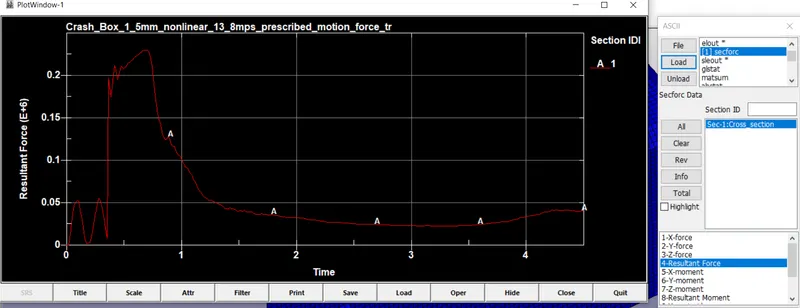
1.5mm Shell thickness
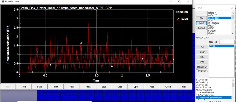
Mid node acceleration
1.2mm shell thickness
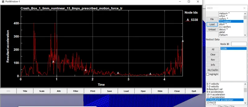
The acceleration is zero till the crash box strikes the rigid wall. Since we used initial velocity, there should actually be deceleration, but we didn’t model the road friction and other parameters in the simulation and so deceleration is zero in the beginning. The node’s acceleration peaks at 0.5ms
1.5mm Shell thickness
Here, the node experience less resultant acceleration as the crash box starts to buckle beyond node 5538. So most of the energy is being absorbed in the farther section and the node 5538 moves very little.
History option provides options to plot Energy, Displacement, Velocity, Acceleration of global, part, element, node, etc with DT equal to DT specified in D3Plot
ASCII provides options to plot data types that we requested in Database ASCII keyword
GLSTAT: Shows information about Global data ex. Energy plot
1.2mm shell thickness
1.5mm Shell thickness
Directional X stress, Strain
1.2mm Shell thickness
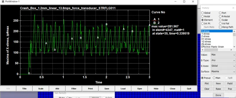
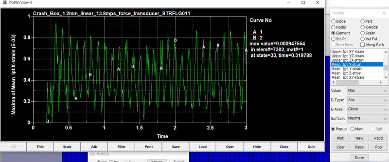
As the model bounces back from the rigid wall, maximum stress and strain values oscillate in the X direction as is evident from the animation. The stress developed propagates from the side hitting rigid wall to the free end.
1.5mm Shell thickness
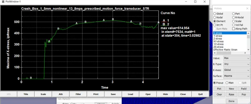
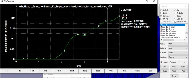
As we used imposed velocity, the model buckles after hitting the rigid wall and hence the stress and strain increases continuously in the X direction.
Directional Y stress, Strain
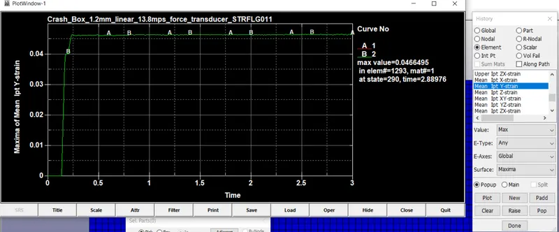
1.2mm Shell thickness
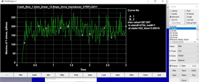
As the model bounces back from the rigid wall, there isn’t much strain the Y direction and is less than that of in X direction.
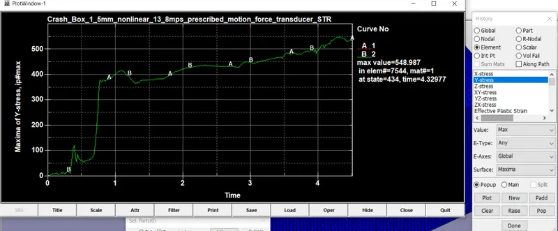
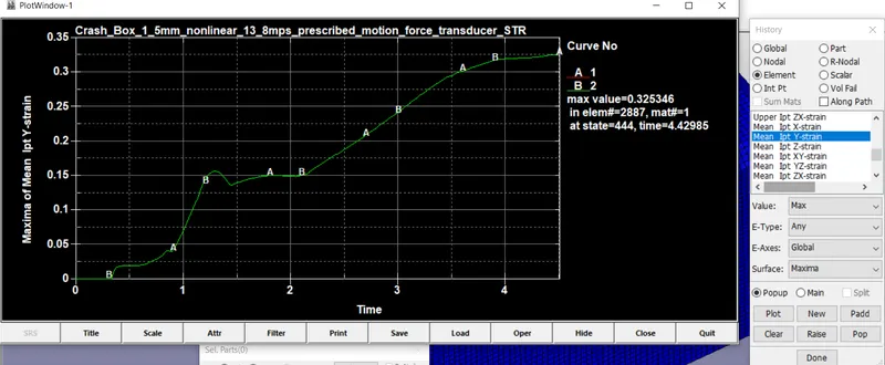
1.5mm Shell thickness
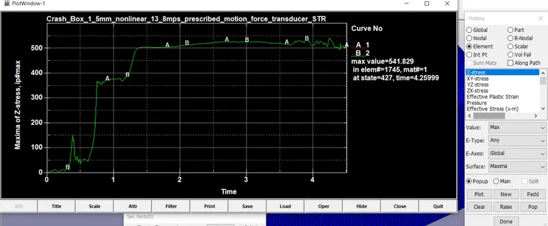
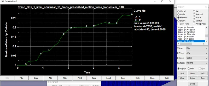
As the model continues with the same velocity throughout the simulation, the model buckles in Y and Z direction and correspondingly, stress and strain values increase
Directional Z stress, Strain
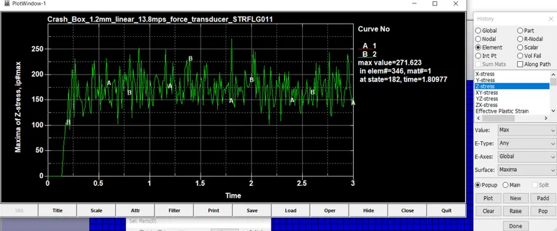
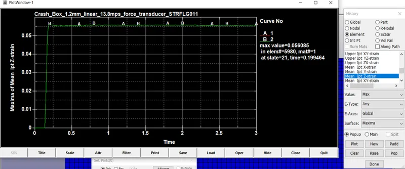
1.2mm Shell thickness
As the model bounces back from the rigid wall, there isn’t much strain the Z direction and is less than that of in X direction.
1.5mm Shell thickness
As the model continues with the same velocity throughout the simulation, the model buckles in Y and Z direction and correspondingly, stress and strain values increase