Week - 4 - crash box simulation
Objective:- The aim of this project is to analyse the crash analysis of box with different shell thickness and compare the different parameters as follows:
Cross sectional forces at the mid plane.
Acceleration of a node at the midplane.
Maximum directional stress and strain along the longitudinal axis.
Energy plots mentioned and Comparing acceleration and stress/strain plots for the 1.2/1.5 shell thickness box.
All the above scenarios are to be carried out by following the given instructions which include
Creating a *RIGIDWALL_PLANAR.
Considering the steel as the box material.
Assigning an Initial velocity of 50kmph = 13.888 mm/ms.
Following a (g,mm,ms) unit system
Procedure:-
Model:
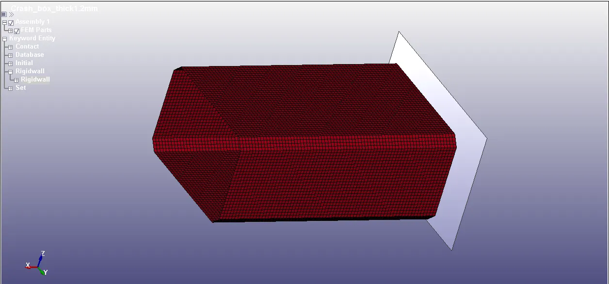
Rectangular crashbox with rigid wall
Section:
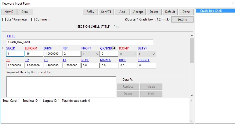
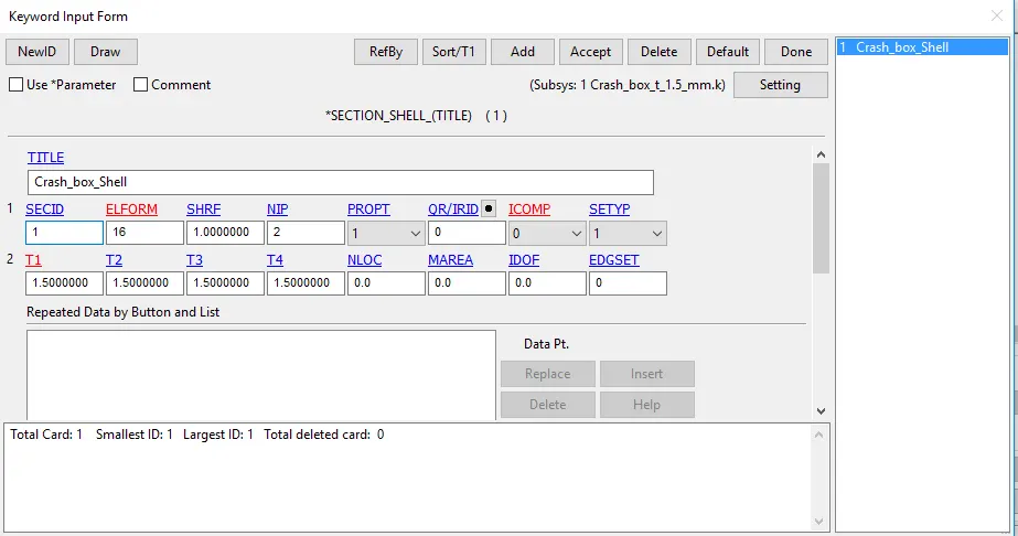
Section is created with ELFORM 16 for fully integrated shell element
Thickness 1.2mm
Thickness 1.5mm
Material:
MAT_24_linear piecewise plasticity is used with defining propeties of STEEL.
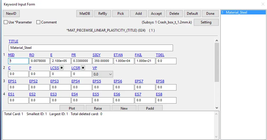
MAT_24 with properties of STEEL
Part:
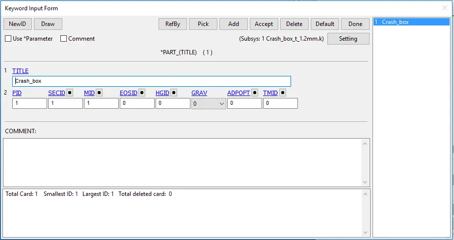
Assigning of material and section to the part
Rigidwall:
Rigidwall is created at a distance of 15mm away from starting node of crashbox
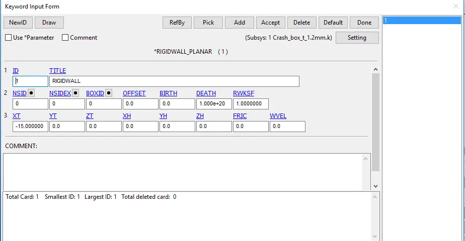
Rigidwall for simulation
Initial velocity:
Initial velocity required for this simulation is 50 kmph. As we are using unit system of 'gm-mm-ms' , 50 kmph is converted to mm/ms which is equal to 13.88 mm/ms.
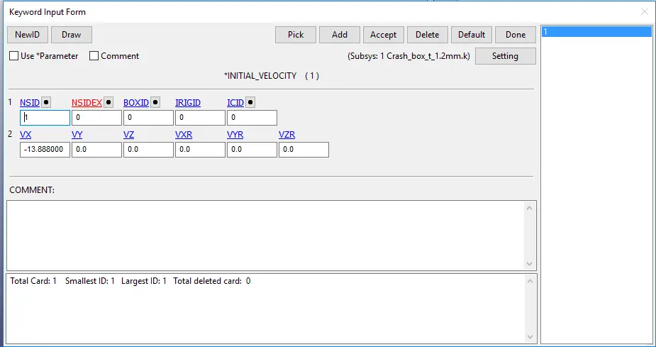
Initial velocity card
Contact:
Automatic single surface contact is created for Crashbox as self contact. Control force transducer card is created for getting value of contact force.
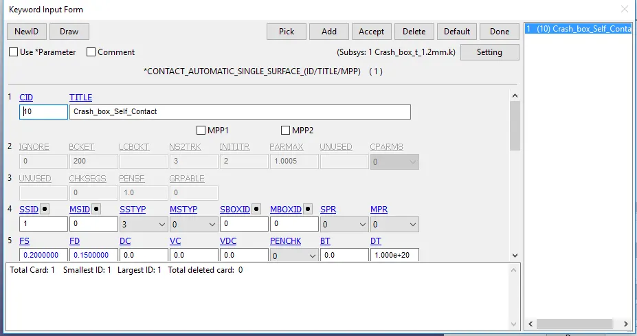
Contact automatic single surface card
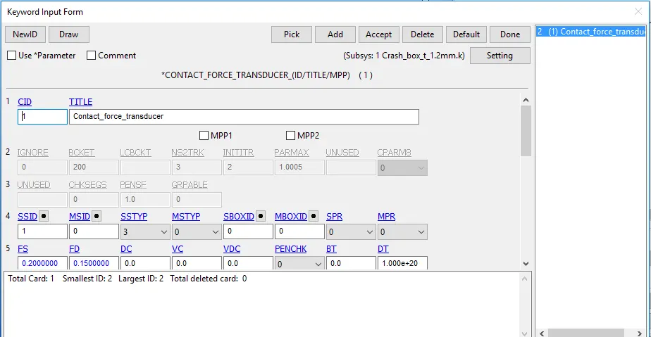
Contact force transducer card
Control Cards:
Control_Energy card is used for controlling hourglass energy and sliding energy
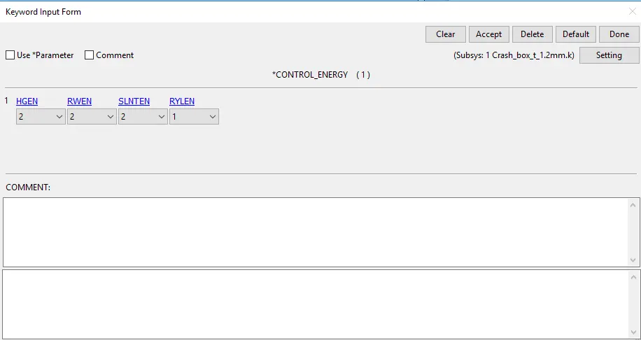
Control_Energy card
Control_termination is used for giving end time of simulation which in our case is 5 ms
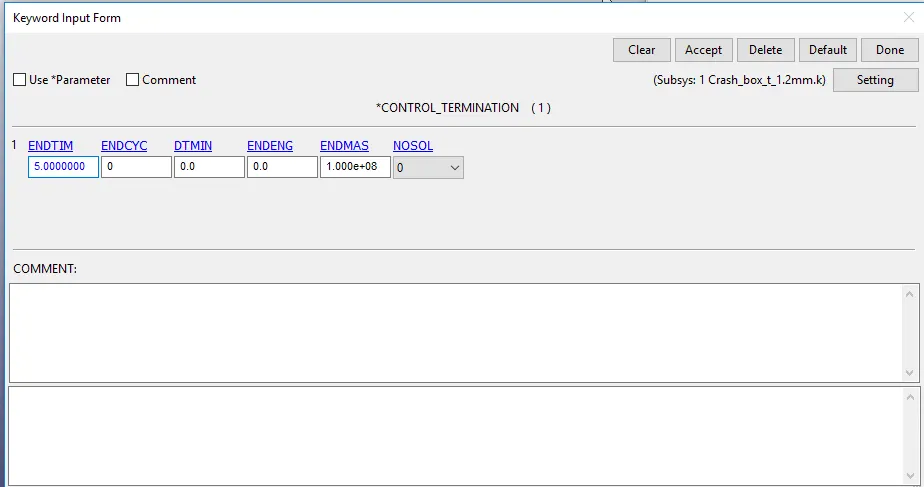
Control_termination
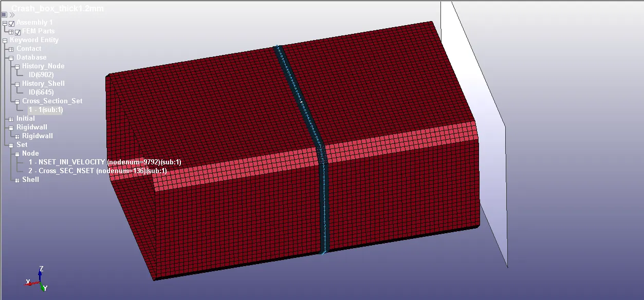
Middle node or shell for data:
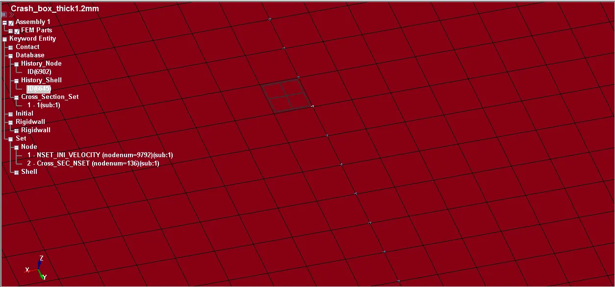
Cross-section:
Solution of Output:
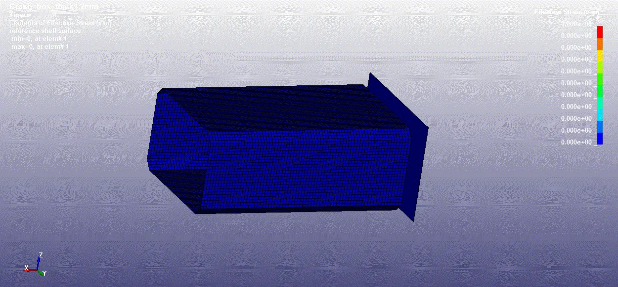
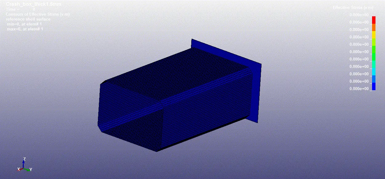
Comparing different thickness of output results:
Simulation of Crashbox thickness 1.2mm
Simulation of Crashbox thickness 1.5mm
Cross-section force across mid plane:
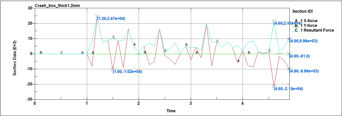
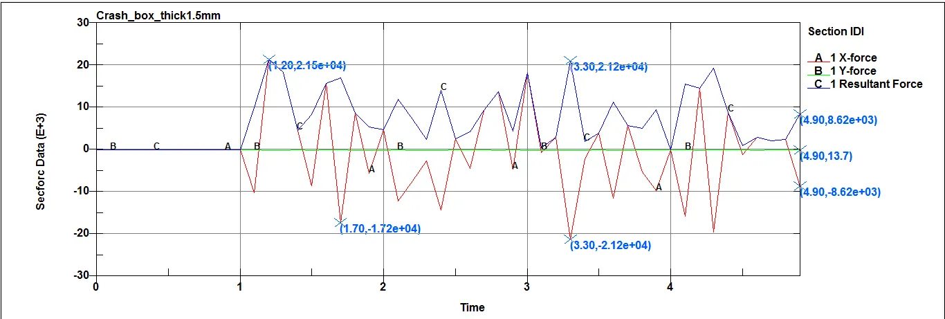
The resultant cross sectional force across Mid plane element for thickness 1.2 mm and 1.5 mm at the instant of impact is 24.7 KN and 21.5 KN and at the end of simulation is 9.96 KN and 8.62 KN respectively.
Acceleration at Mid plane Node 6902:
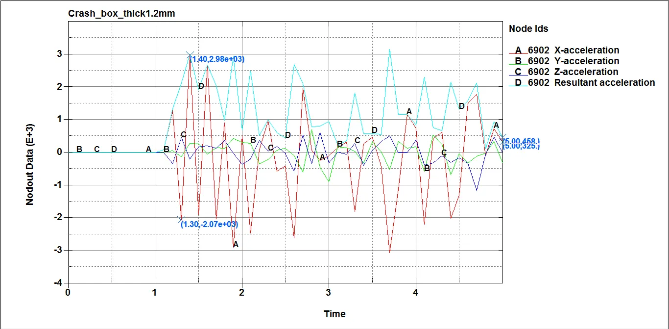
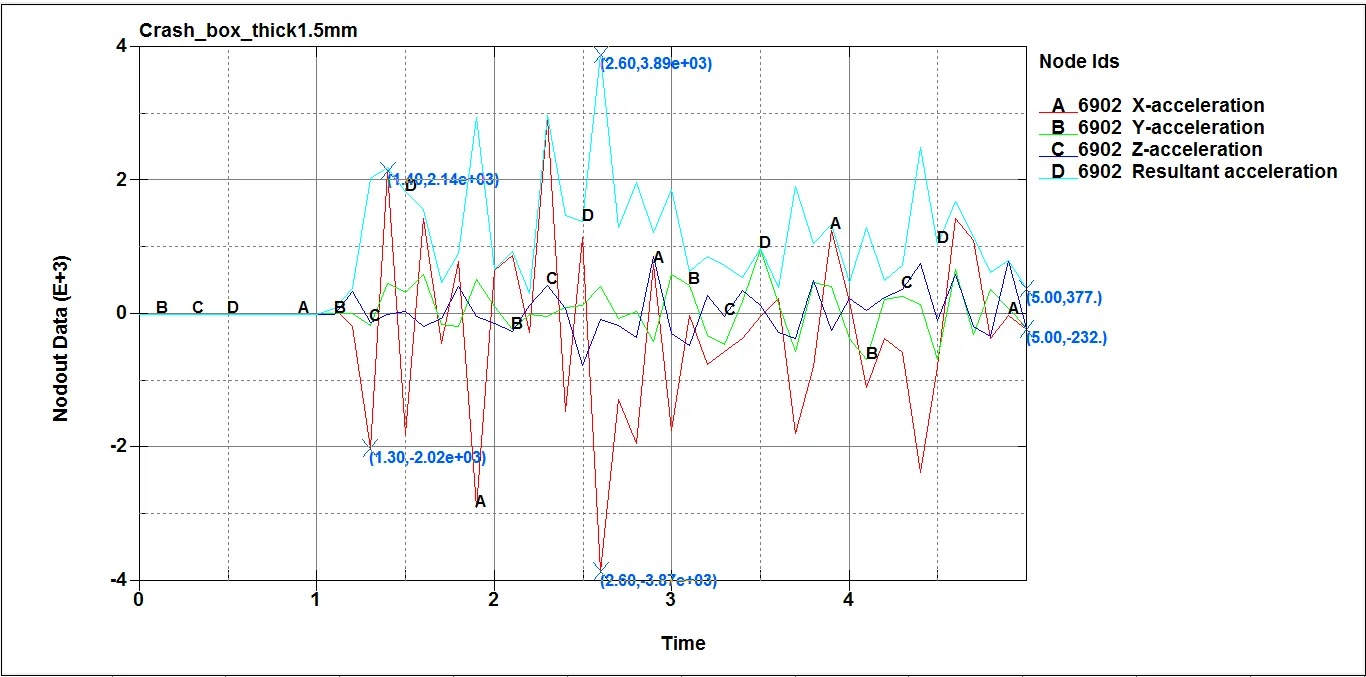
The resultant mid plane acceleration at Node 6902 for thickness 1.2 mm and 1.5 mm at the instant of impact is 2980 mm/ms2 and 2140 mm/ms2 and at the end of simulation is 458 mm/ms2 and 377 mm/ms2 respectively.
Directional Stress:-
Stresses along X-axis:
At instant of Impact 1.2 ms
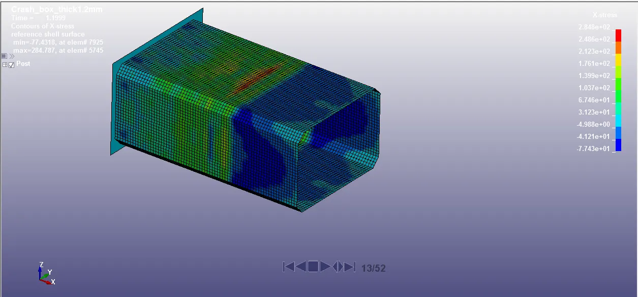
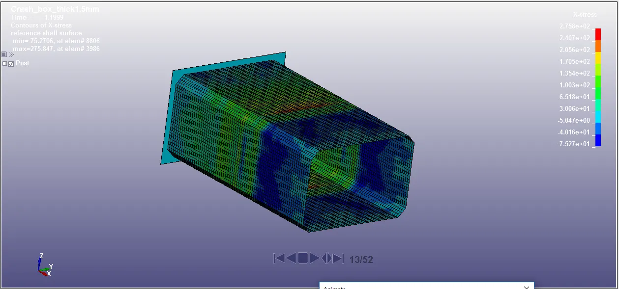
The value of X-stresses at instant of impact of thickness 1.2 mm and 1.5 mm are 284.8 MPa and 275.8 MPa respectively which means that there is no big difference in betweeen them in terms of stress value at instant impact.
At end of simulation 5 ms
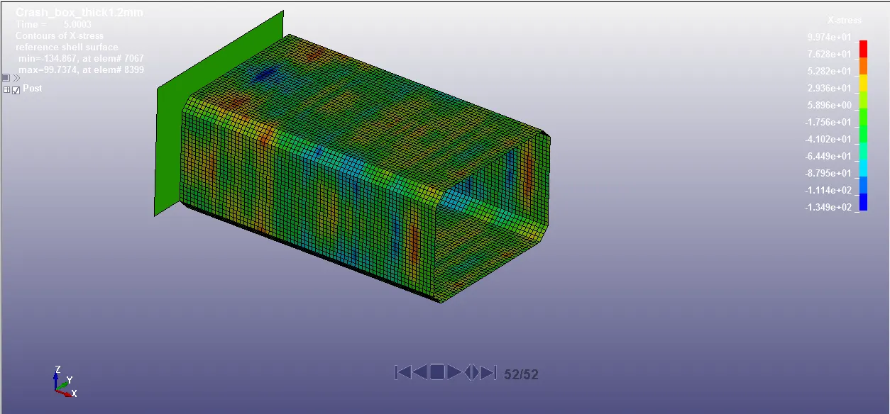
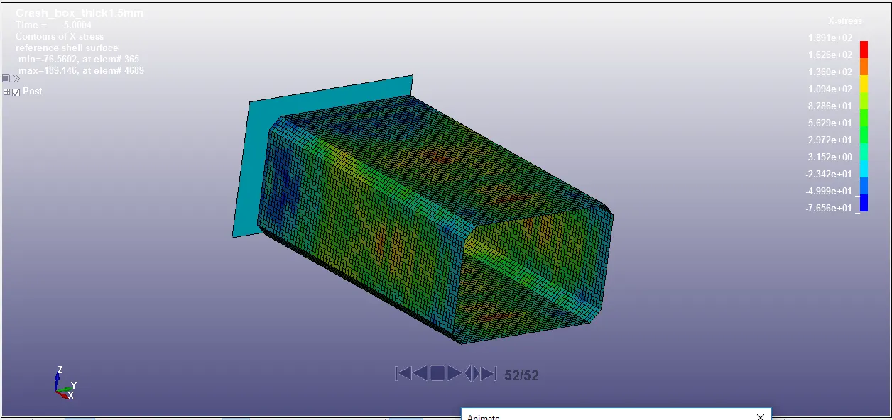
The value of X-stresses at end of simulaton 5 ms of thickness 1.2 mm and 1.5 mm are 99.74 MPa and 189.1 MPa respectively. This means that more stress is obtained for more thickness of shell element.
Stresses along Y-axis:
At instant of Impact 1.2 ms
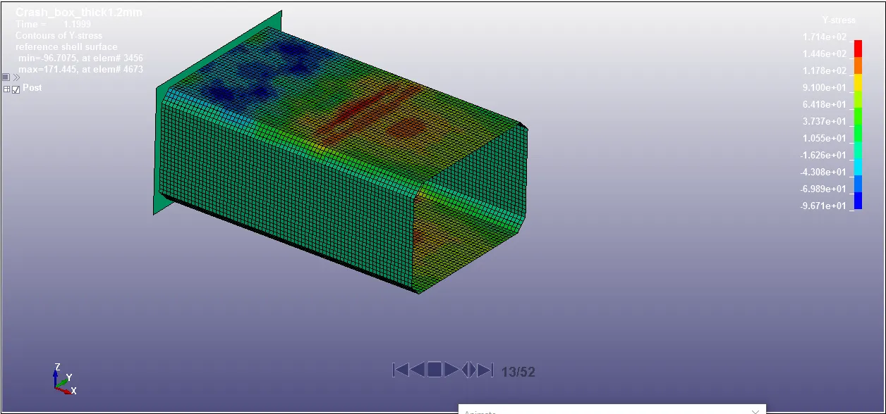
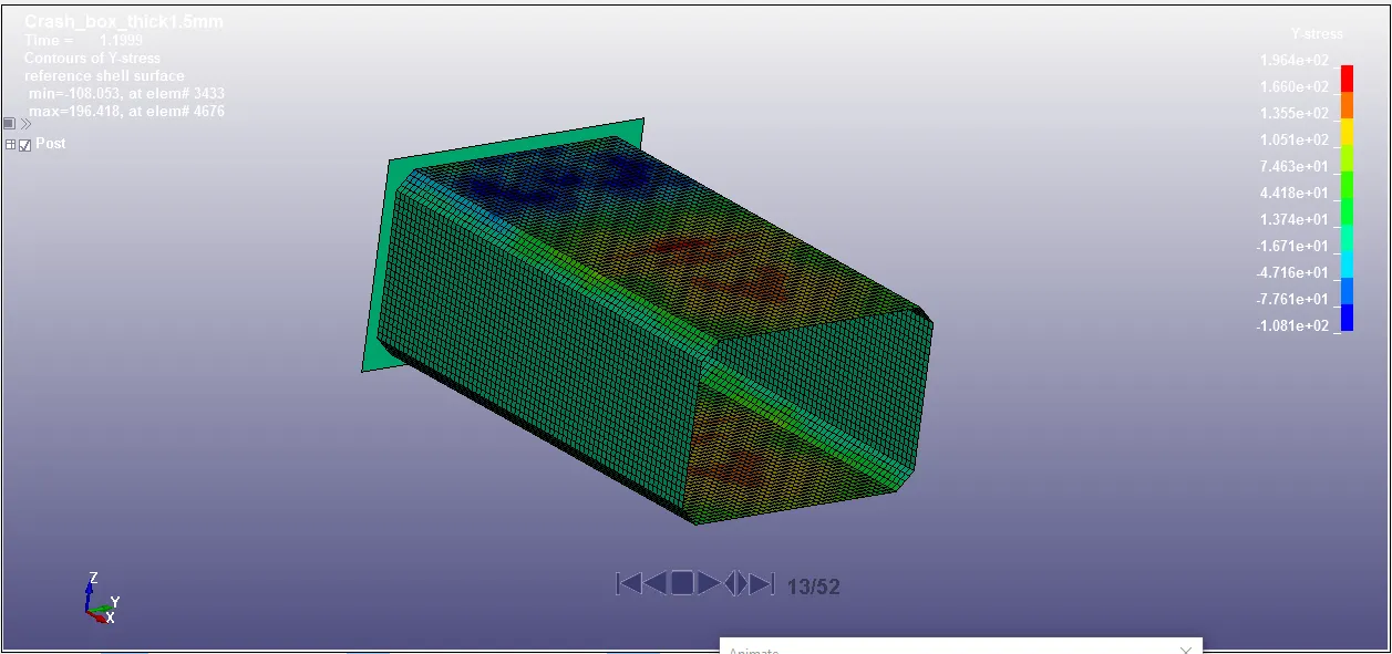
The value of Y-stresses at instant of impact of thickness 1.2 mm and 1.5 mm are 171.4 MPa and 196.4 MPa respectively. There is no big difference at instant of impact in terms of stress.
At end of simulation 5 ms
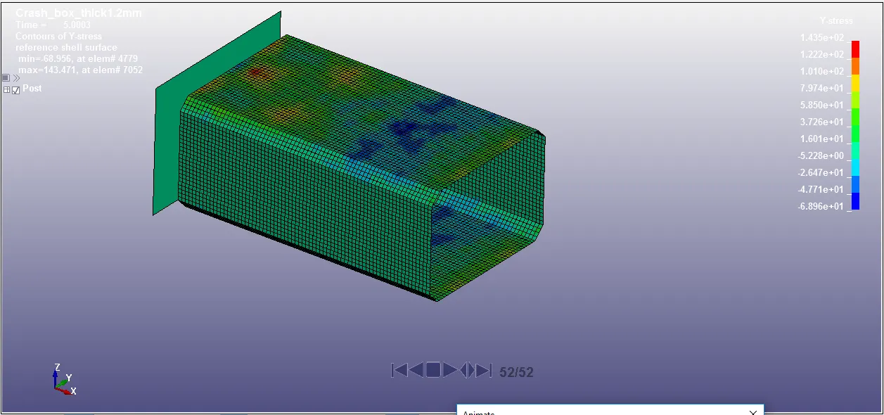
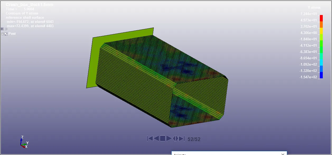
The value of Y-stresses at end of simulaton 5 ms of thickness 1.2 mm and 1.5 mm are 143.5 MPa and 72.44 MPa respectively. More Y-directional stress is obtained in thickness 1.2 mm as compared to thickness 1.5 mm.
Directional Strain:-
Strains along X-axis:
At instant of Impact 1.2 ms
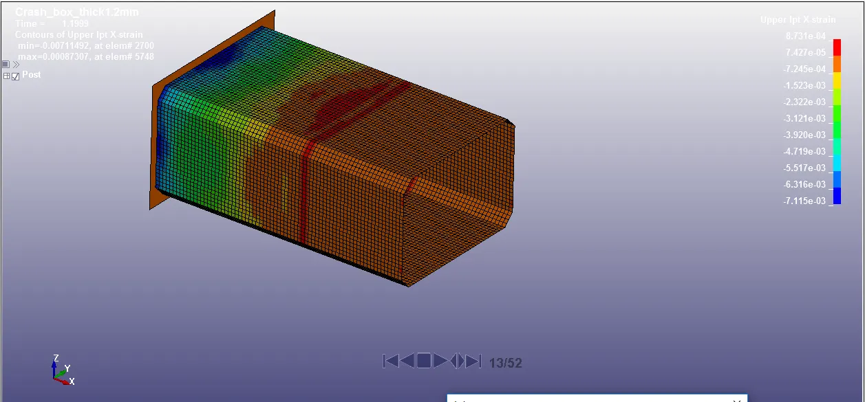
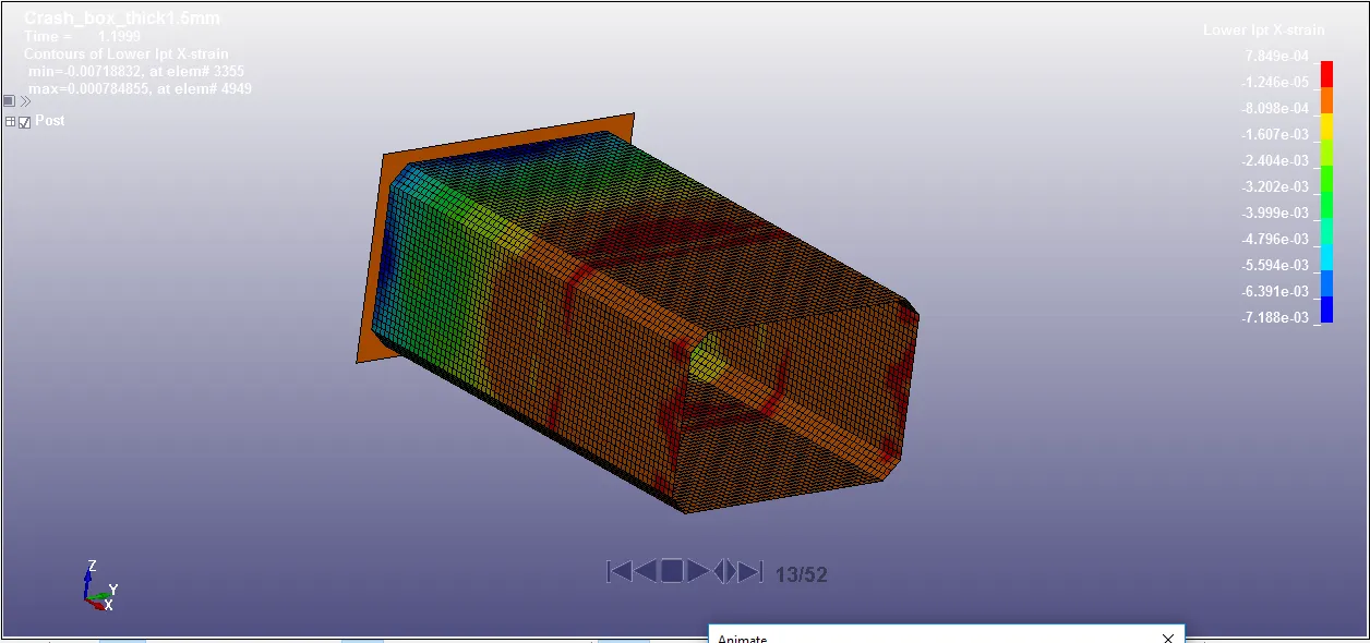
The value of X-strain at instant of impact of thickness 1.2 mm and 1.5 mm are 8.731e-4 and 7.849e-4 respectively. The value of strain deformation obtained at instant of impact is almost neglectible.
At end of simulation 5 ms
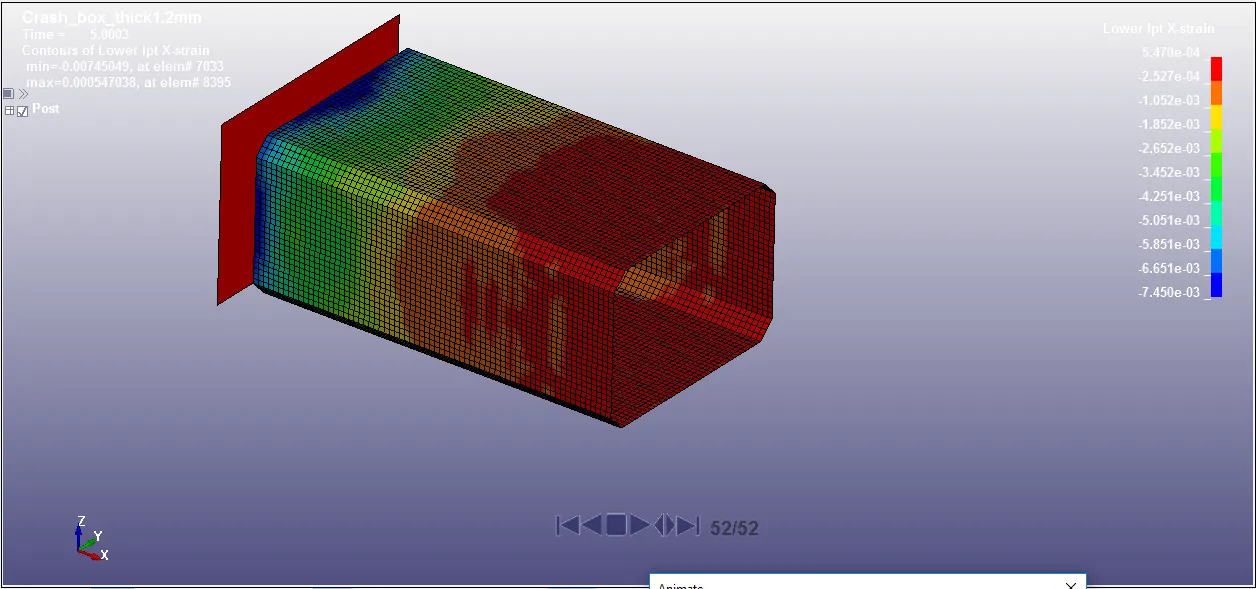
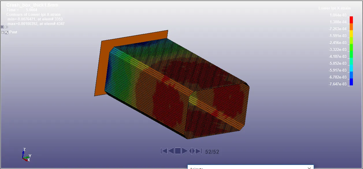
The value of X-strain at end of simulation of thickness 1.2 mm and 1.5 mm are 5.470e-4 and 1.004e-3 respectively. The value of strain along X-direction at end of simulation is very small.
Strains along Y-axis:
At instant of Impact 1.2 ms
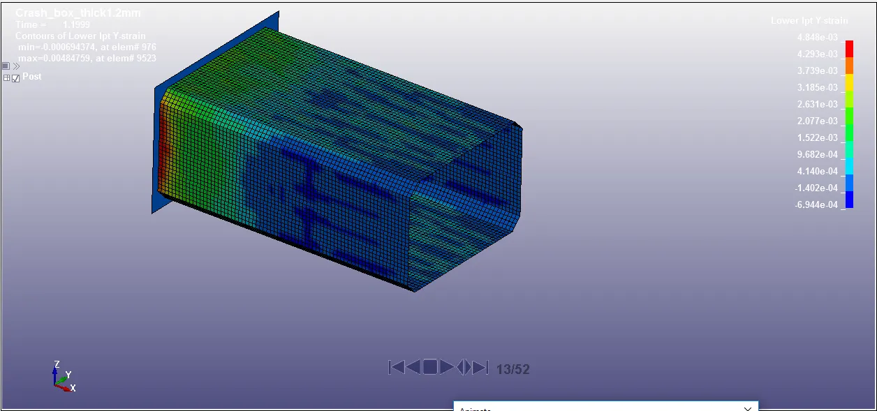
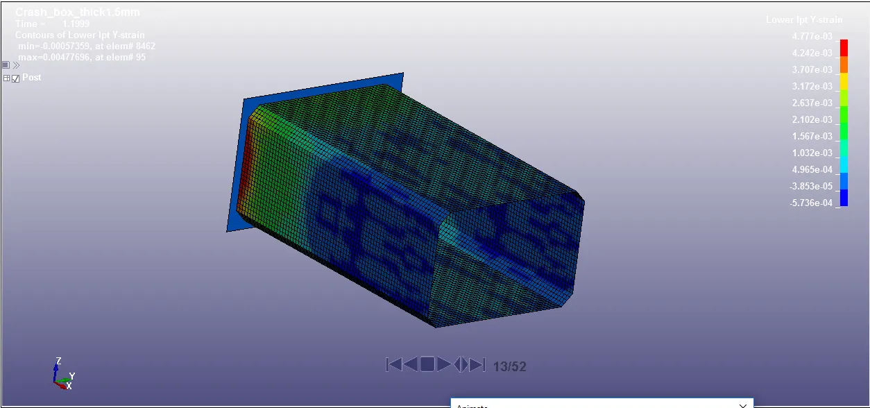
The value of Y-strain at instant of impact of thickness 1.2 mm and 1.5 mm are 4.848e-3 and 4.777e-3 respectively. For both thicknesses the value of Y-directional strain deformation at instant of impact is same.
At end of simulation 5 ms
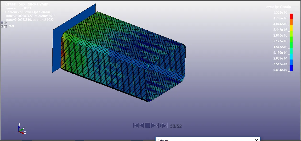
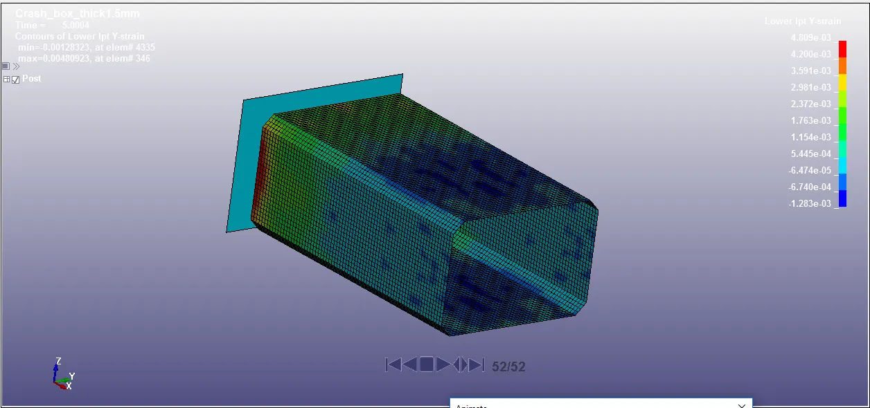
The value of Y-strain at end of simulation of thickness 1.2 mm and 1.5 mm are 5.338e-3 and 4.809e-3 respectively. For both thicknesses the value of Y-directional strain deformation at end of simulation is almost same.
Contact Force:-
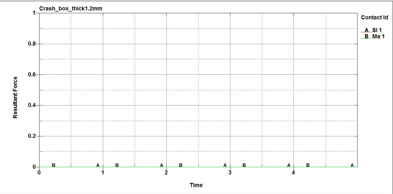
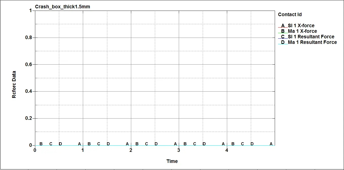
The resultant Contact force on both slave and master are zero for both shell thickness.
Rigid wall force:-
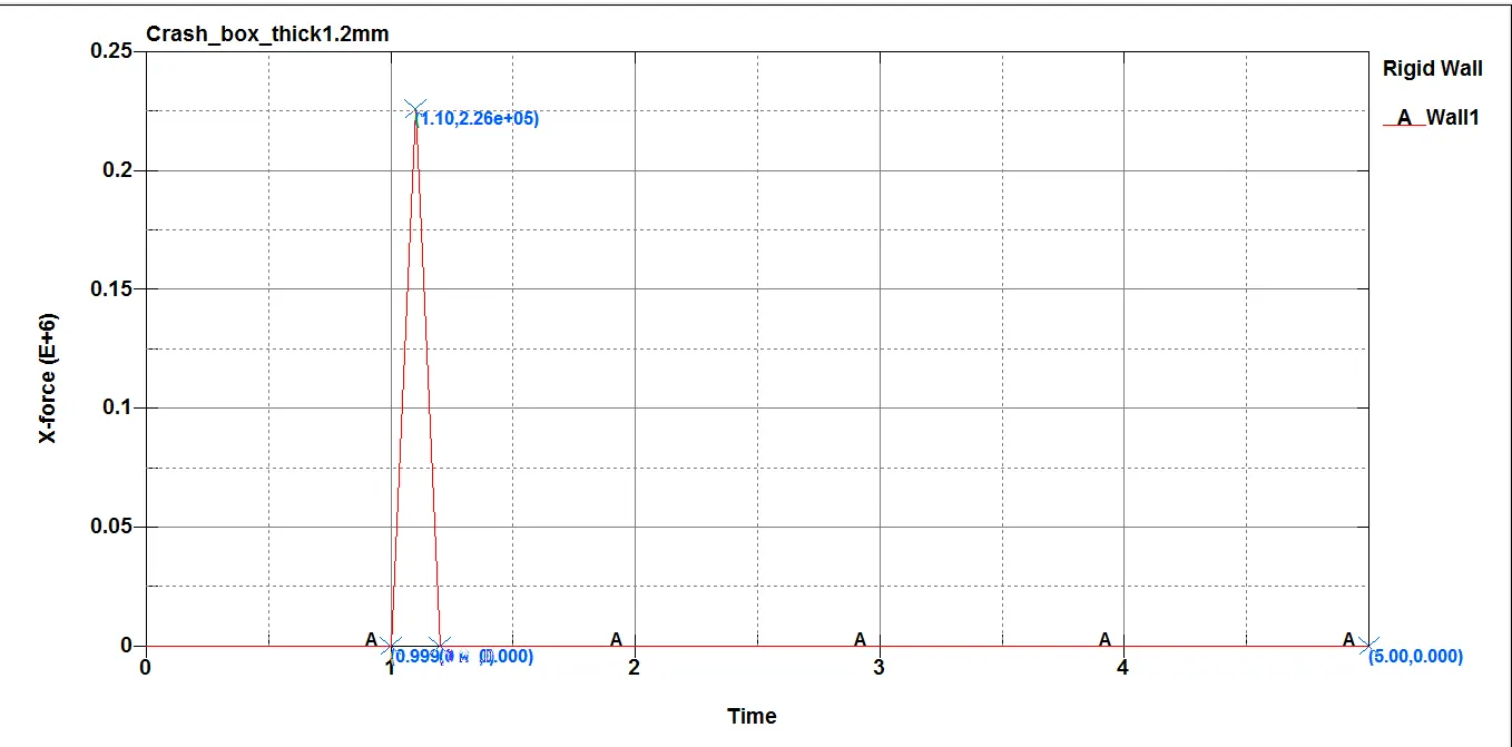
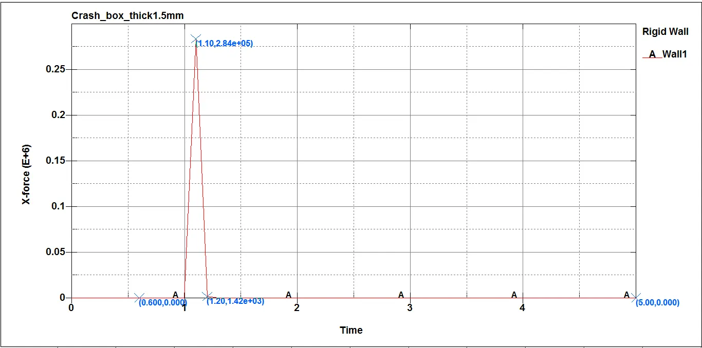
Rigid wall force obtained along X-direction for thickness 1.2 mm and 1.5 mm at instant of impact are 2.26e-05 N and 2.84e+05 N respectively. More force on rigid wall is obtained for higher thickness shell value.
MATSUM energy:-
For thickness 1.2mm
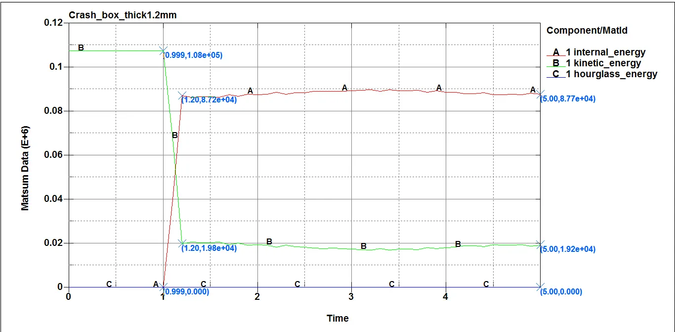
| Parameters | Before impact At 0.99 ms | Instant impact at 1.2 ms | At end of simulation 5 ms |
| Kinetic Energy | 1.08e+05 | 1.94e+04 | 1.92e+04 |
| Internal Energy | 0.000 | 8.72e+04 | 8.77e+04 |
| Hourglass Energy | 0.000 | 0.000 | 0.000 |
For thickness 1.5mm
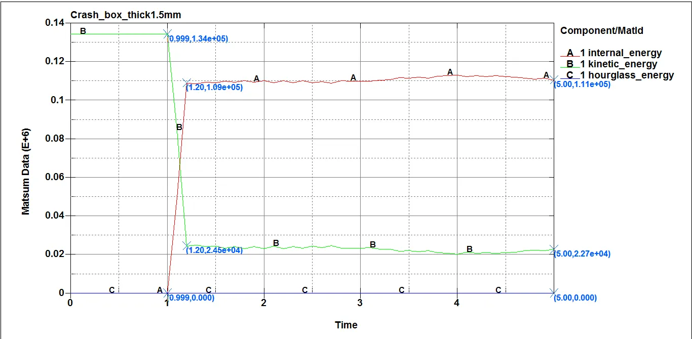
| Parameters | Before impact At 0.99 ms | Instant impact at 1.2 ms | At end of simulation 5 ms |
| Kinetic Energy (J) | 1.34e+05 | 2.45e+04 | 2.27e+04 |
| Internal Energy (J) | 0.000 | 1.09e+05 | 1.11e+05 |
| Hourglass Energy (J) | 0.000 | 0.000 | 0.000 |
GLSTAT Energy:-
For thickness 1.2mm
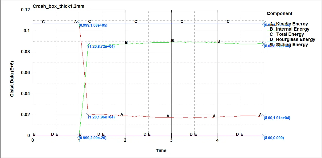
| Parameters | Before impact At 0.99 ms | Instant impact at 1.2 ms | At end of simulation 5 ms |
| Kinetic Energy (J) | 1.08e+05 | 1.96e+04 | 1.91e+04 |
| Internal Energy (J) | 2e-20 | 8.72e+04 | 8.77e+04 |
| Total Energy (J) | 1.08e+05 | 1.08e+05 | 1.08e+05 |
| Sliding Energy (J) | 0.000 | 0.000 | 0.000 |
| Hourglass Energy (J) | 0.000 | 0.000 | 0.000 |
For thickness 1.5mm
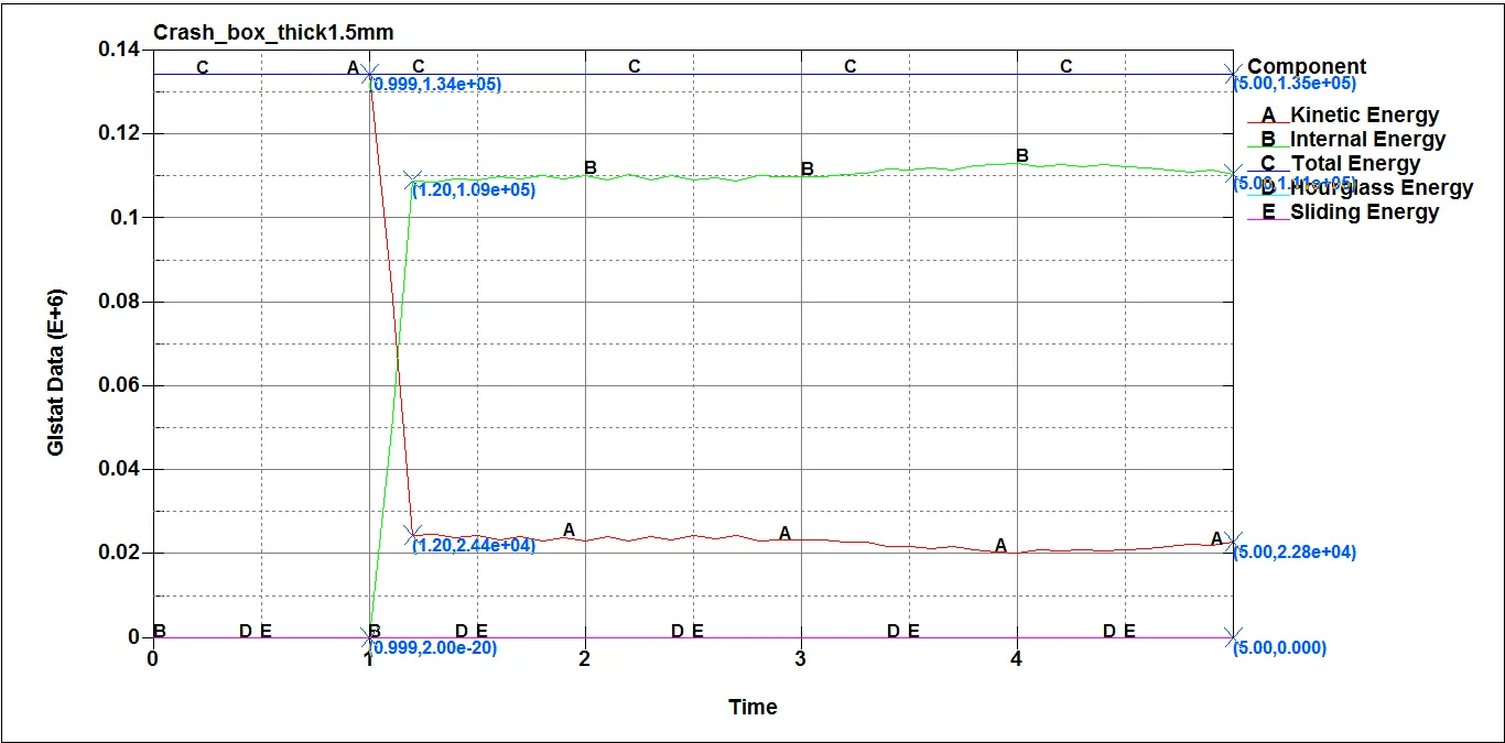
| Parameters | Before impact At 0.99 ms | Instant impact at 1.2 ms | At end of simulation 5 ms |
| Kinetic Energy (J) | 1.34e+05 | 2.44e+04 | 2.28e+04 |
| Internal Energy (J) | 0.000 | 1.09e+05 | 1.11e+05 |
| Total Energy (J) | 1.34e+05 | 1.34e+05 | 1.34e+05 |
| Sliding Energy (J) | 0.000 | 0.000 | 0.000 |
| Hourglass Energy (J) | 0.000 | 0.000 | 0.000 |
Comparing Acceleration and Stress/Strain for 1.2mm and 1.5mm shell thickness at instant of impact:
| SL NO. | Parameters | Thickness 1.2 mm | Thickness 1.5 mm |
| 1 | Stress along X-direction | 284.8 MPa | 275.8 MPa |
| 2 | Strain along X-direction | 8.731e-04 | 7.849e-04 |
| 3 | Acceleration at Node 6902 | 2980 mm/ms2 | 2140 mm/ms2 |
Conclusion:-
There is no much between the the stress between the two thicknesses. The values cannot completely be true because there are uneven peaks and valleys in the almost all the plots that has been put in the report. The Stress values are very below the yield stress 350MPa. The acceleration is for the 1.2mm thickness is slightly higher than the other. Since, the simulation satisfied the first case i.e., crashes onto the rigidwall and rebounds completely, there is no significant deformation that can be observed as the interation between the box and the rigidwall is only 0.99-1.2 ms so strain is negligible and the contact force for the slave and master is zero. The Residual Strain is taken because the box is having some initial kinetic energy and hits the rigidwall. So, it can be assumed through SHOT PEENING the box gets compressed at the impact time where some residual stress forms which indicates that there is residual stress which is very much less 'Micro units' negligible.