Impact Simulation of Crash box with different thickness and comparison of its Post processing Results
AIM
To study the crash simulation of a crashbox crashing into a rigidwall
OBJECTIVE
We have a crashbox meshed model with us and we need to prepare a deck for simulation in which the crash box crashing into a rigid wall .At first we just assign onlly an elastic material to the crash box so that we can check for the funtioning of the deck,Since in case of any error made while creating the deck will be shown once after we do the solving.So we can make sure that the problem with alal other keywoprds are nill and so that we can then assign a non linear material to the crashbox.Then we need to do the simulation with 1.2 and 1.5 thickness.Then from that we need to extract the details such as follows;-
- Input .k file and output files (d3plot, glstat, sleout, rcforc)
- Animation of the final simulation
- Cross-sectional force generated in the middle of the crashbox (along its length)
- Acceleration plot of a node in the middle of the crashbox (along its length)
- Maximum directional stress and strain along the length of the crashbox (X strain, Y strain etc)
- Plot of all energies (total, internal, kinetic, hourglass, sliding)
- Compare the accelerations and stress/strain plots of 1.2/1.5mm crashboxes.
1) CASE SETUP
Here we first need to import the only mesh CRASH BOX model keyword file into the LS Prepost.For that open LS Dyna > File > Open > browse for the crash Box .k model >Open.This will open the model for theCrash Box in the LS Prepost.First we need to create the material for the crash box .We are creating a Linear plasticity MAT_24 material for the crashbox.At the same time applying a non linear material at the begining irtself may throw us errors because of the complexity it creates for the problem.So in order to check whether our proroblem is defined correctly we are first applying an elastic material and check the deck by running it.If everything seems fine.Then we can move on to define a non linear material.Here in Ls DYna there is no unit system.Its always user wish to define the unit system as per our wish.Here we are using a unit system gm/mm/ms. since this is an impact test and it will be carried out for about 150 milliseconds because the entire impact will happen for maximum for 150 milliseconds.Normally the impact will be end in 120 milliseconds but the rebounding will also happens for the next 30 Milliseconds.
Material And Section Creation
To create the linear elastic material for Crash Box we need to Choose Model on side tool bar area > Select KEYWORD > Choose MAT Keyword > Open the MAT_ELASTIC keyword CARD >Select the Crash BOX .>Input the values of Rho,E, and Poisson's Ratio in that Card >Accept > Done.Also since we need to apply the thickness to our crash box we need to asssign thickness to the shell elements.This can be done by Model >keyyword>place radio button in all > Section >Shell >Choose th values as shown below > accept >Done.In case 2 with the non linear material we need to give thickness as 1.5 mm in section card.
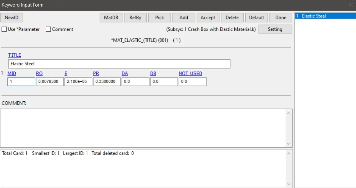
Fig 1.1 MAT _ ELASTIC
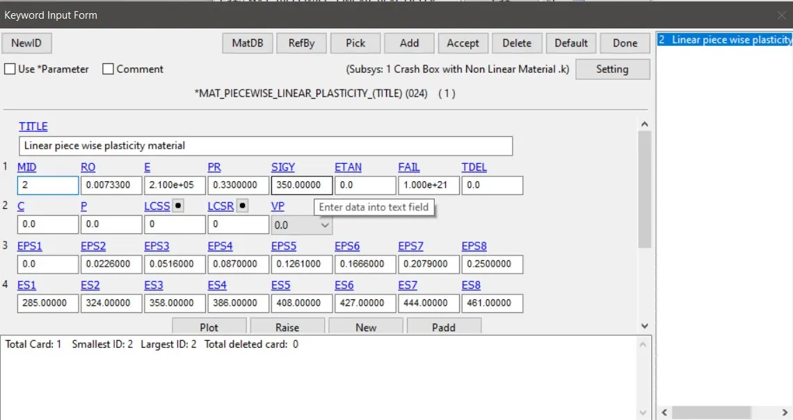
Fig 1.2 MAT_24 Piece wise_linear_plasticity Card
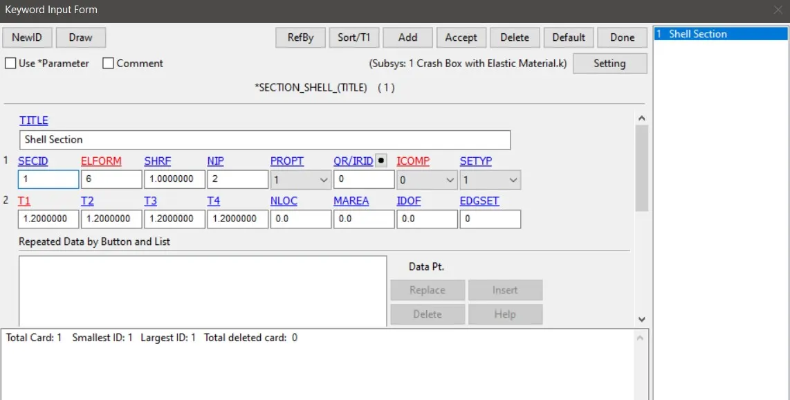
Fig 1.3 Section_Shell Card
Material and Section Assigning
Then we need to assign these Material and the section to the crash box.For this Go to part keyword >give the part ID >Assign material >assign section > Accept >Done.
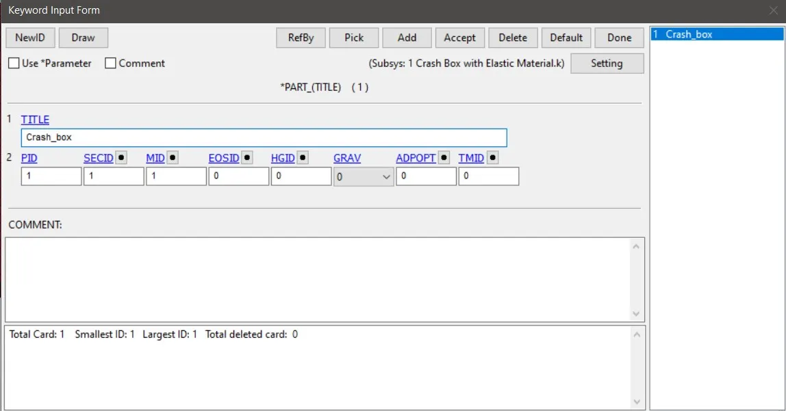
Fig 1.4 Part Material and section Assigning
In case 2 with the non linear material we need to give thickness as 1.5 mm in section card.And then we need to apply that to the part Card.
Creation of Rigid Wall
UIn the simulation we need to crash the Crashbox witha rigid wall.For that to make happen we need to first create a Rigidwall in the model.This can be done by Model > Create Entity >Select the Rigid Wall > Place the radio button in planar > Select the option N1 - N2 > then seleect the choose two nodes in such a way that the order in which the nodes are choosen will be the same direction in which we want our rigid wall normal to be ( Choose the normal of the rigidwall should be in opposite direction to which the crash box is travelling) > Accept > Done.
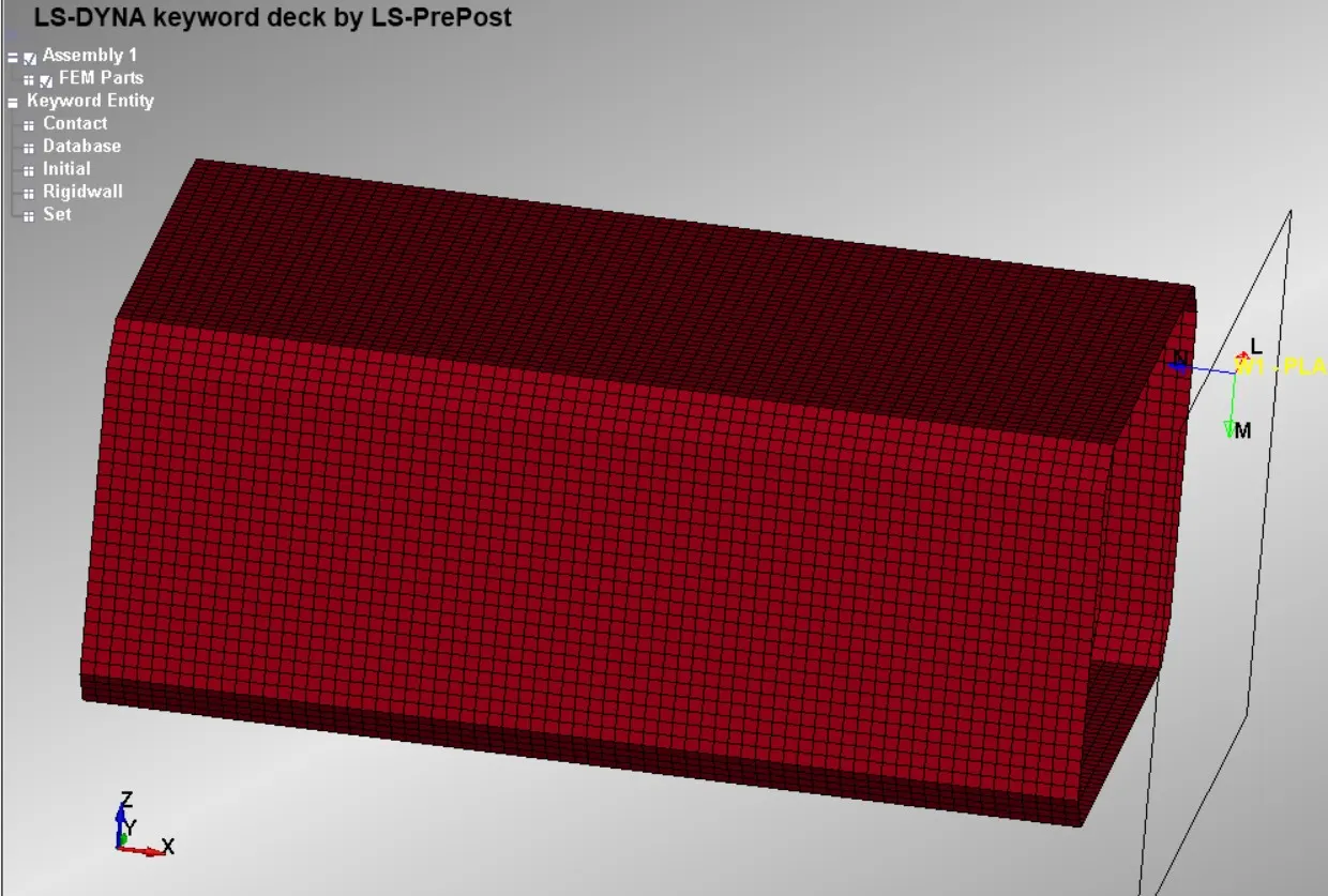
Fig 1.5 Rigid wall normal in oppossite direction to that of velocity of the crashbox
Applying Boundary condition
As a boundary condition we are applying a speed of 50kmph which is equals to 13.88 mm/ms .To apply this,we need to apply this to entire crash box nodes.So we need to create a node set data.For this go to create entity > Set data >Set Node data > select the netire noes in crash box > Apply> Done.This will create the crash box node set with the ID we specified.Then we need to create Velocity card by Model > Keyword > Intial > Velocity > Since the cordinate axis in which we neeed the crah box to move is in x- Axis give 13.88 value in Vx box > Select NSID as the Id of the node set we just created > accept > done.
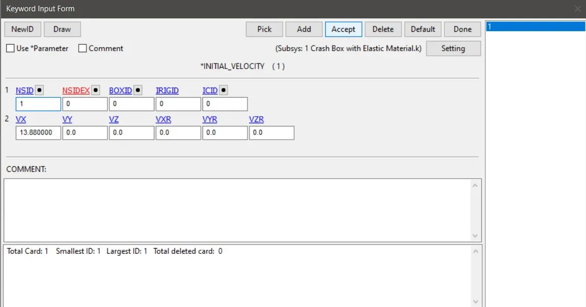
Fig 1.6 Intial Velocity
CONTACT CREATION
Since we are impacting the crash box with a rigid wall there is no need to make a new contact as the rigid wall is in built have the contact condition .We need to specify only the Node Set ID of the crashbox in the NSID column in Rigid Wall Card.But As there is the possibility of the crash box to buckles after the impact and it will came into self contact.As in real scenario we can see that the sheet metal after buckling will not penetrate into other .So inorder to get the simulation like that of the real case we need to create a self contact in the deck.This can be done by Model > keyword >Contact >Automatic Surface to Surface > Set SSTYP as 3 > Assign the slave as a part set of the crash box >Accept > Done.
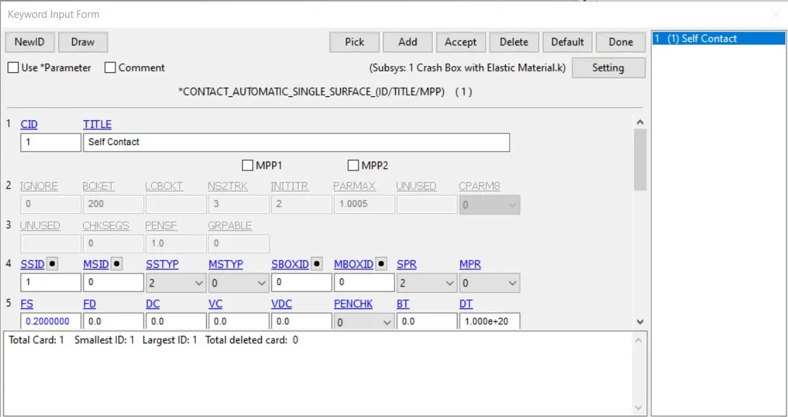
Fig 1.7 Contact Automatic Surface to surface card
CONTROL CARD CREATION
We need to specify for how long our simulation would run.This can be incorporated using the control termination Card.For this Model > Keyword > Place the radioo button in ALL > Control >Termination > Specify the End Time as 5 mm > Accept > Done.
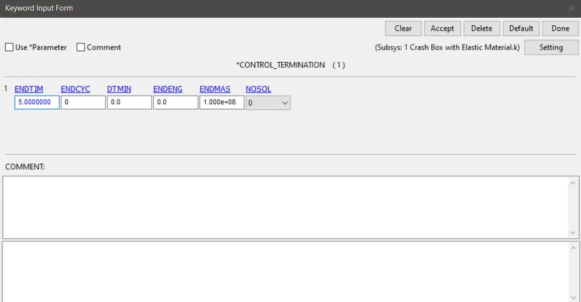
Fig 1.8 Control Termination Card
Since we need to request for hour glass energy and sliding energy we need to create a control energy card also .This can be formed by Model > Keyword > Place the radioo button in ALL > Control > Energy > Set HGEN and SLNTEN as 2 > Accept > Done.
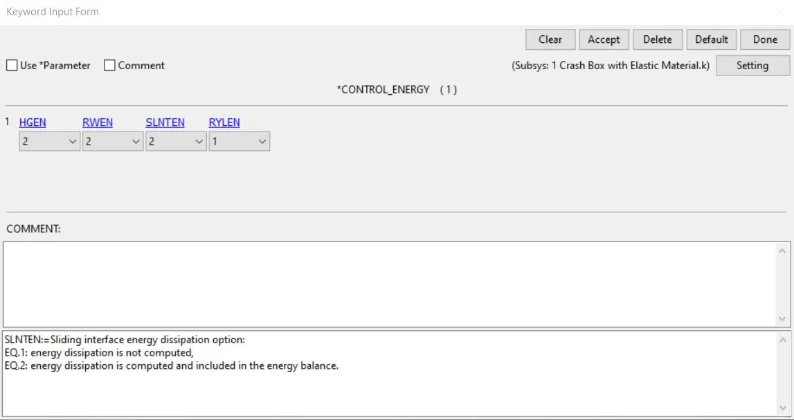
Fig 1.9 Control Energy
Then we need to create a section in the crashbox mesh as we are asked to find out the sectional force through the lenght of the crasjh box .So inorder to make a section, First we create a node set runnin in a line in the middle across the crash box and also a element set as the referance for the node set.This will basically create the section.
DATABASE CREATION
This is the card space where we need to specify what are our variables required.So in ascii option card we need to set in GLSTAT,MATSUM,SLEOUT,RCFORCE,RW FORCE,SECFORC which gave us the energy values,part energies,sliding energy,rigidwall contact force,and section force respectively.And set the dt which is the time for recording the plot values as 0.1 mm.Here we also gives NODE_out in ascii option card as we need to get the node acceleration values.But even we asked for the secforce and node out ,we need to define the area where we need to store these values .For defining the section we need to create CROSS SECTION_SET in database keyword .Then assign NSID and SSId in it.Similarly for defining the NODE in whiich we want the output time history,we create a HISTORY _NODE card in database keyword .Then we specify the node in which we need to get the output .Similarly to define the strain in the D3PLOT itslef we need to specify EXTENT_BINARY Card in the database keyword and set STRFLAG as 1 .So that the strain will be recorded.
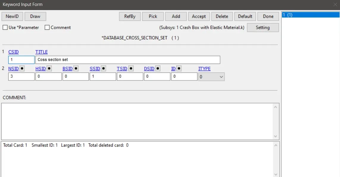
Fig 1.10 Cross Section Set CARD
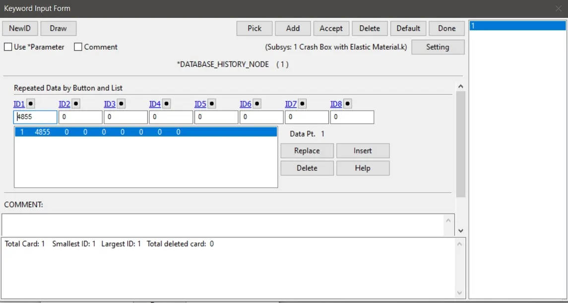
Fig 1.11 History Node CARD
To store the stress and strain value at the middle in differant axis ,we can ask for the element history.her in LS dyna we can use ELOUT in ascii option to request forelement output.This can be stores by using the BINARY >HISTORY SHELL >Specify the ID of elementwe need to take the history (here we take Shell element with ID1191)> Accept >Done.
Then in the Model >keyword >Binary >binary D3THDT >Give dt as 0.1 ms >Accept >Done.
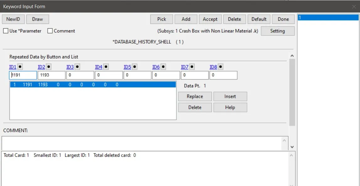
Fig 1.12 HISTORY_SHELL CARD
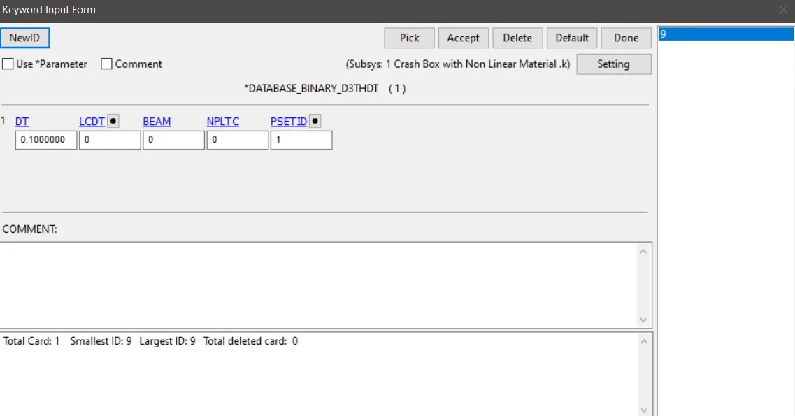
Fig 1.13 D3THDT CARD
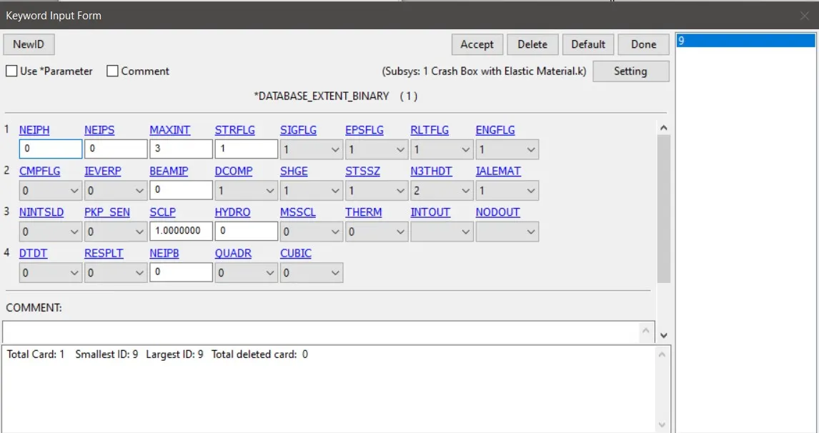
Fig 1.14 EXTENT_BINARY CARD
2) Post Processesing
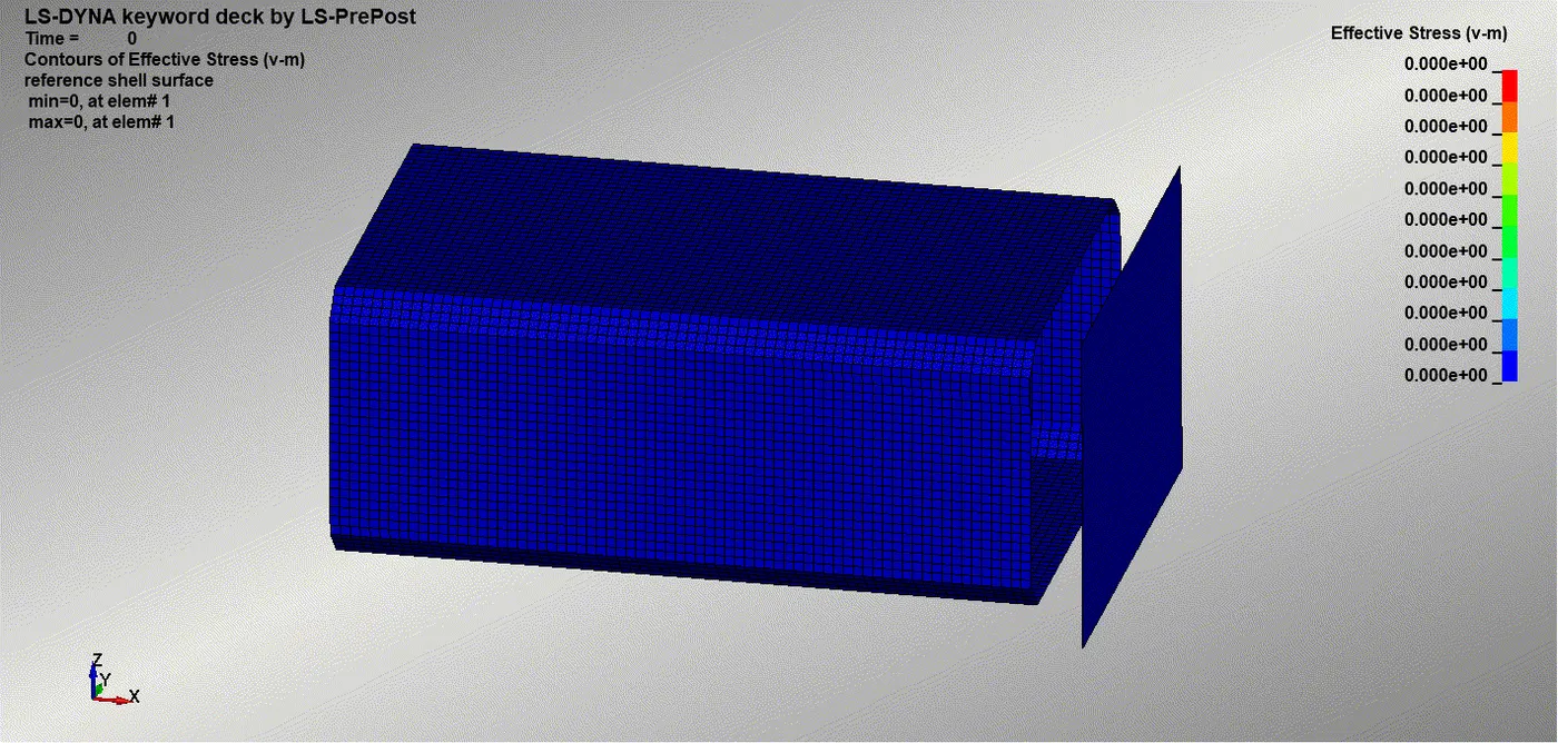
Fig 2.1 Simulation of the Crash

Fig 2.2 Energy curve of crash box having 1.2 mm thickness
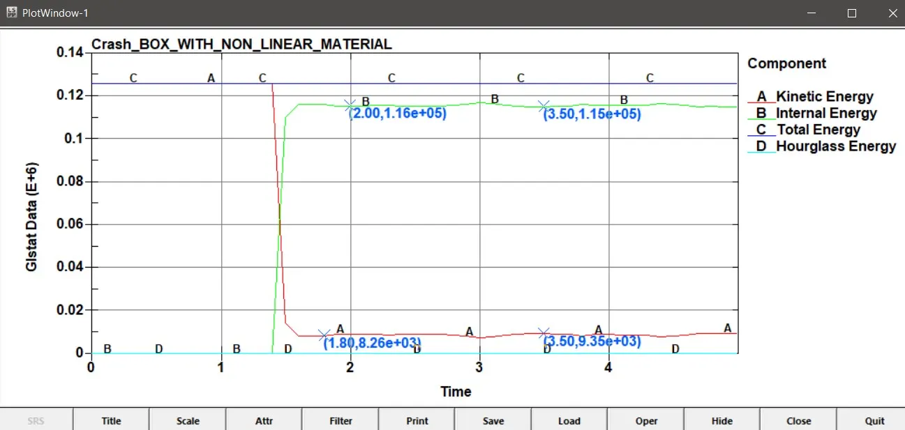
Fig 2.3 Energy curve of crash box having 1.5 mm thickness
The above figure is making sense ,as soon as the crashbox makes its contact with the Rigidwall at the 1.4 ms, the kinetic energy is reducing to a large extent and the internal energy is rising high as the kinetic energy is converted into the internal energy. But the KE is .Here but te effective stress devoloped is below 300 MPA which is less than the yield strength value which is the 350 MPa we input in the material card .So The component will not experience plastic deformation ,as it is still in its in elastic region.It will release the internal energy as it will again converted to kinetic energy and the crash box rebounds some distance and then it stops when both the internal energy and kinetic energy are zero.

Fig 2.4 X -Acceleration of node 4855 in crashBox with thickness 1.2 mm
Till the 1.5 millisecond ,prior to the impact ,the acceleration is zero,it is beacuse we are applying a constant velocity ,so the acceleration is zero till then.But after the impact the acceleration curve is showing rapid variations.And after the complete reversal of internal energy back to kinetic energy after the 5 th millisecond ,the accleration will again goes back to zero acceleration as the velocity will became constant.
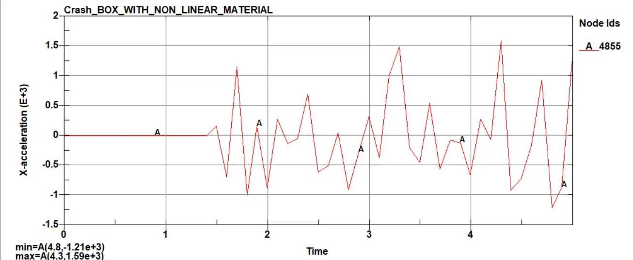
Fig 2.5 ACCELERATION OF NODE 4855 in CRASH BOX with THICKNESS1.5 mm
Accleration in the crash box with thickness 1.5 mm is comparitively less,This is beacuse as the thickness increases the mass of the component is increasing ,thereby it reduces the rebounding velocity and so as the acceleration.
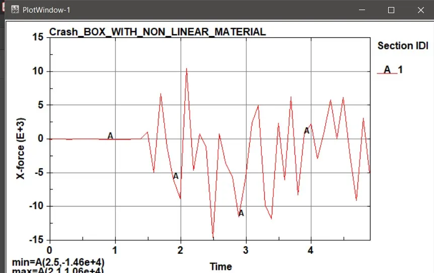
Fig 2.6 Sectional force through X Axis(along the length) in crash box with thickness 1.2 mm
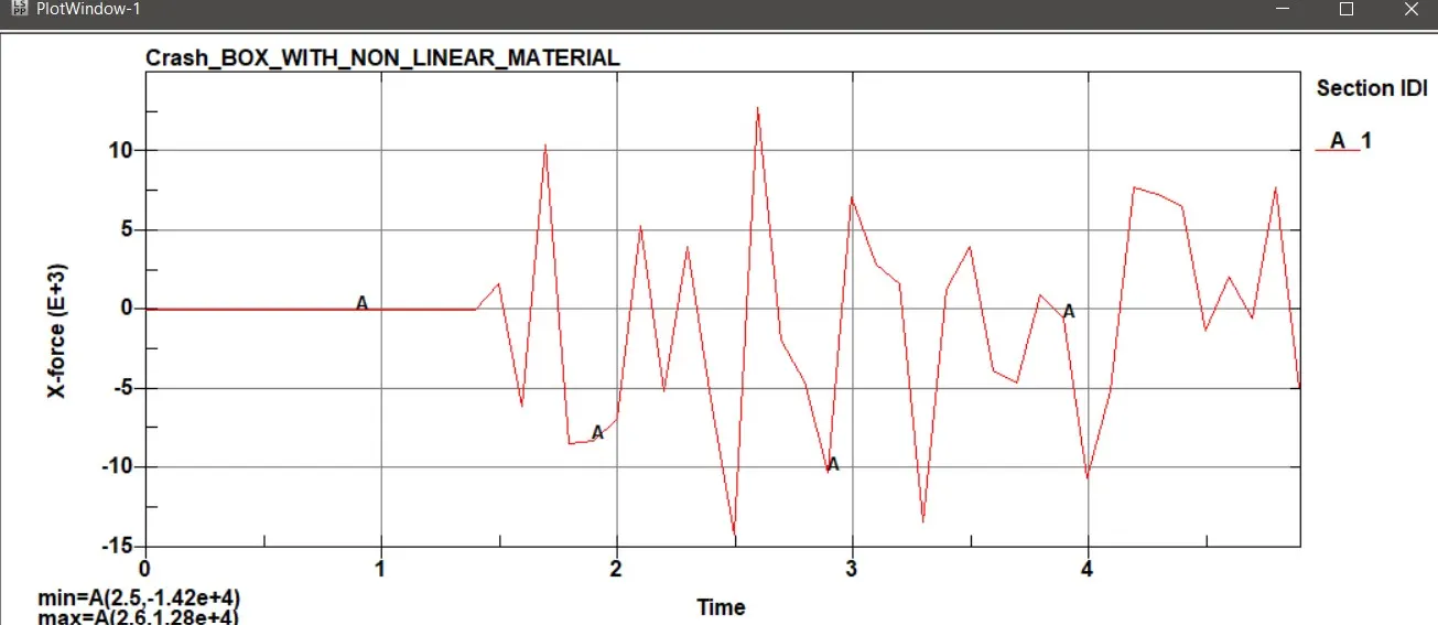
Fig 2.7 Sectional force through X Axis in crash box with thicknes 1.5 mm
The velocity applied on both crashbox is same but dure to increase in thickness the mass of second crashbox is more .So the KE with which the crash box impacts will be more here.So that the force imparted to the that crah box will be more ,that is why the sectional force is more in crashbox with greater thickness
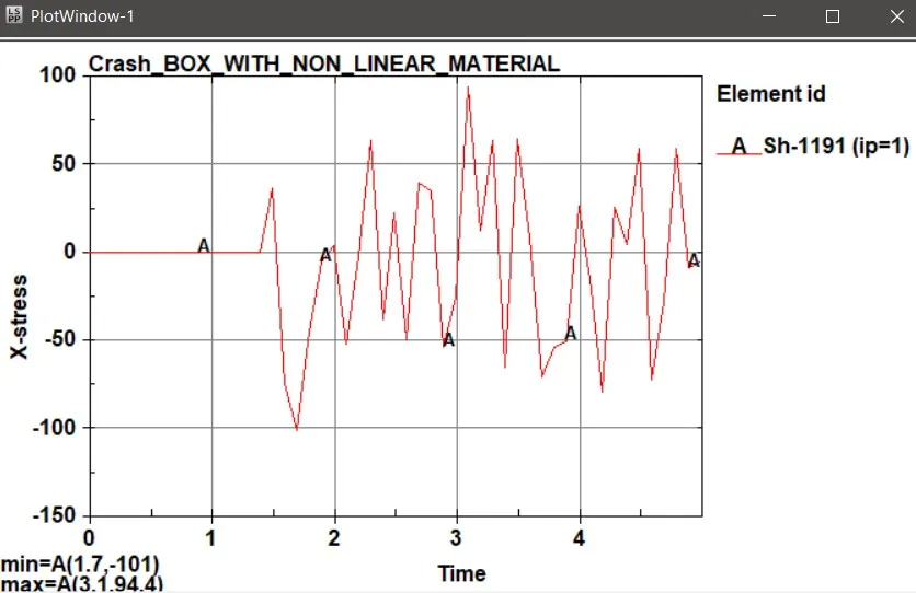
Fig 2.8 Stress in X axis in crashbox with 1.2 mm thickness
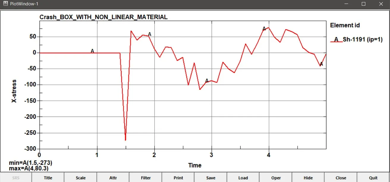
Fig 2.9 Stress in X axis in crashbox with 1.5 mm thickness
When the surface area increases the stress will be decreased. The stress values are increased when the thickness of the component will be increased and stiffness also increases.When the thicknes increases it increases the susrface area and stiffness of the componenet therby the stress absorbed by the component also increased.This is why in x dirrection the component with 1.5 mm thickness is absorbing 273 MPa and the that with hicknesss 1.2 mm absorbing only 94.4 Mpa.
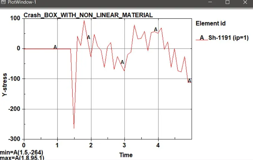
Fig 2.10 Stress in Y axis in crashbox with 1.2 mm thickness
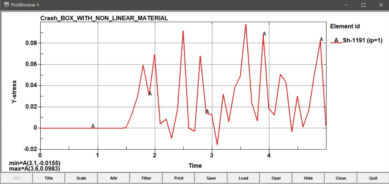
Fig 2.8 Stress in Y axis in crashbox with 1.5 mm thickness
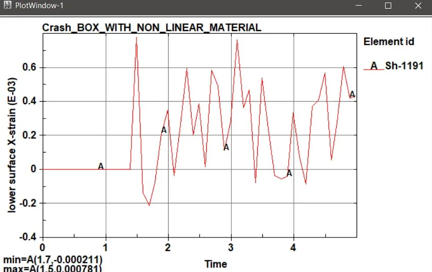
Fig 2.9 Strain in X axis in crashbox with 1.2 mm thickness
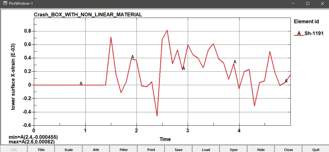
Fig 2.10 Strain in X axis in crashbox with 1.5 mm thickness
In the proportionality limit the stress uis directly proportional to strain a the young's modulus is constant .So like the stress is more in 1.5 mm thickness crashbox,So as the strain also more in 1.5 mm thickness crashbox.
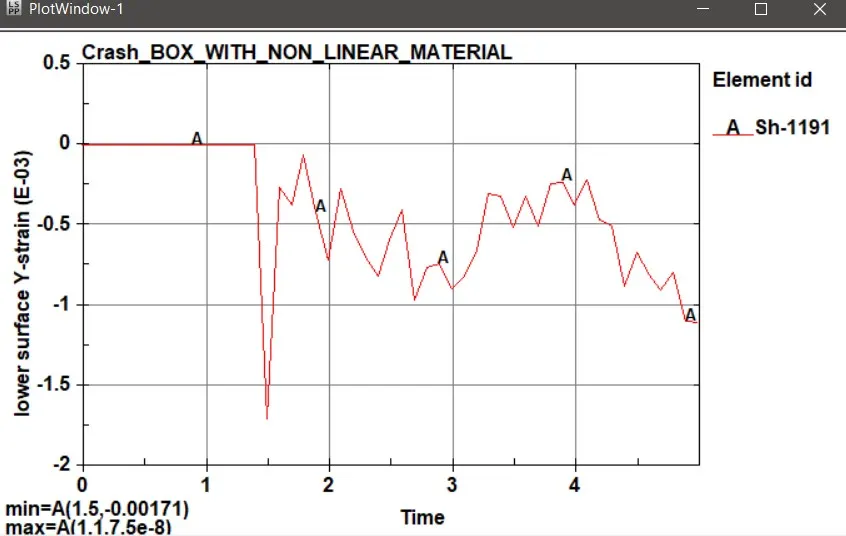
Fig 2.10 Strain in y axis in crashbox with 1.2 mm thickness
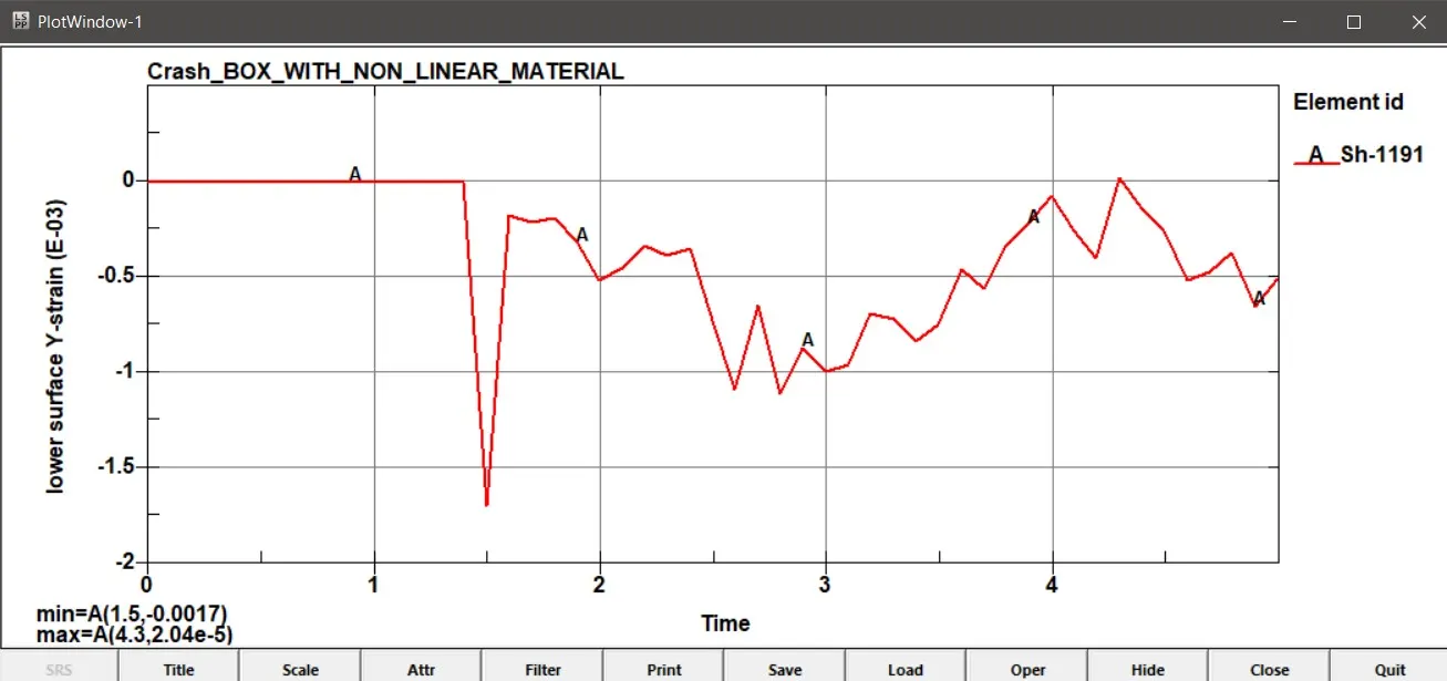
Fig 2.11 Strain in Y axis in crashbox with 1.5 mm thickness
Conclusion
Crashbox is a component which helps in reducing the impact of force on other bodies adjacenet to it by crashing it itself by bsorbing the large amount of shock.So there must be an optiomum thickness for this to make sure the crashbox will not transfer a lot of shock to adjacent bodies ,since the larger thickness having crashbox will transfer a lot of amount of shock to adjacent bodies.So an optimum thickness must be employed to the crashbox so as to make sure that it will absorb a larg amount of energy and crumble itslef so as to protect the other bodies from shock and therby protecting the occupt inside the automobile.