Week - 4 - Crash Box Simulation
Crash box Frontal Impact Analysis
Aim: To study the deformation behaviour and stresses developed in a crash box during a full frontal impact.
Geometry and Spatial Discretization: The part under consideration is a rectangular crash box 250mm long, 150mm wide and 100mm high. The part is meshed with 9656 quad elements ( and 9792 nodes) with shell element formulation 6 (S/R Hughes-Liu) for stiffness hourglass control. The analysis is run for shell thicknesses of 1.2mm and 1.5mm with NLOC = 0 (mid-surface thickness).
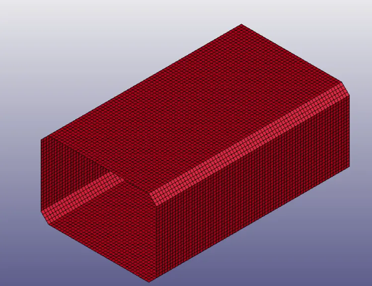
Fig 1: Crashbox meshed part
Constitutive Material Model: The material used is steel with the following properties:
| Sl No | Material Property | Magnitude | Unit |
| 1 | Density | 7.85e-03 | gm/mm3 |
| 2 | Young's Modulus | 2.10e+05 | MPa |
| 3 | Poisson's Ratio | 0.33 | - |
| 4 | Yield stress | 280 | MPa |
| 5 | Tangent Modulus | 1050 | MPa |
The MAT_024 Piecewise Linear Plastic Material card is used for this with a high plastic strain to failure value of 1.0e+20 (implying there would be no failure or deletion of elements in the model).
Contact Definition: An Automatic_Single Surface self contact is defined for the crash box with a penalty formulation and static coefficient of friction of 0.2. IGAP is set to 1 for proper convergence behaviour and other card parameters such as PENMAX and IGNORE are left to their default values.
Rigidwall: A Planar rigidwall is defined at one end (origin) of the model with an offset of 1mm from the crash box. To coefficient of friction is set to 0.2 and all nodes in the model are included for slave nodes.
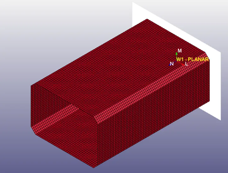
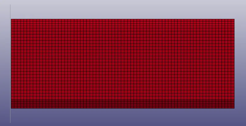
Fig 2: Rigidwall Fig 3: Rigidwall from left side view
Boundary Condition: An initial velocity of 50km/h or 13.88mm/ms is applied to the box through Initial_Velocity_generation keyword. The velocity is applied in the positive X-direction to propel the box towards the rigidwall.
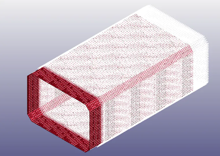
Fig 4: Initial Velocity on the part
A mass of 100kg is added to the model using the Element>Mass_Part keyword. This is to ensure that the box impacts the wall with sufficient kinetic energy (leading to deformation) without increasing the initial velocity.
Analysis Settings: The simulation is run for 5ms with binary plot data requested every 0.1ms. The same time interval is requested for the GLSTAT, MATSUM, SLEOUT, RCFORC, SECFORC, and RWFORC ASCII output files. To compute the hourglass and sliding energies, HGEN and SLEN are set to 2 in the Control_Energy keyword.
Results and Discussion: The crashbox impacts the wall at 0.19988ms and collapses in on itself without any lateral deflections or buckling behaviour.
The energy plots of the two simulations are as shown in Fig 5 and 6. In the case of the box with 1.2, on impact, the kinetic energy drops from 9.46e06 N-mm to 9.89e05 N-mm during which the box absorbs strain energy (shown as internal energy) of 8.63e06N-mm. The energy due to the self-contact levels at a maximum value of 9.79e03 N-mm while the impact with the rigidwall leads to an energy generation of 9.61e04 N-mm. The final total energy at the end of the sim is 9.72e06N-mm.
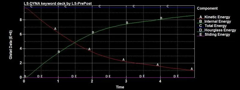
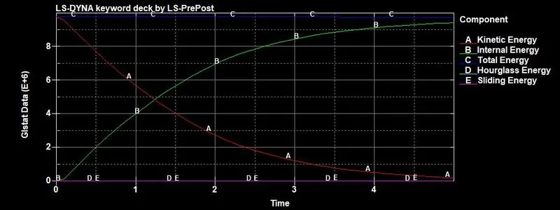
Fig 5: Energy plot for 1.2mm box Fig 6: Energy plot for 1.5mm box
The energy behaviour of the mm thick crashbox is also similar, except for the change in magnitudes of the components. Kinetic Energy drops from 9.77e06 N-mm to 1.80e05 N-mm during the 5ms run when the box stores strain energy of 9.43e06 N-mm. Contact energy tops at 1.02e04 N-mm and the max rigidwall (stonewall) energy developed is 1.40e05N-mm. The final total energy of the system is 9.76e06 N-mm.
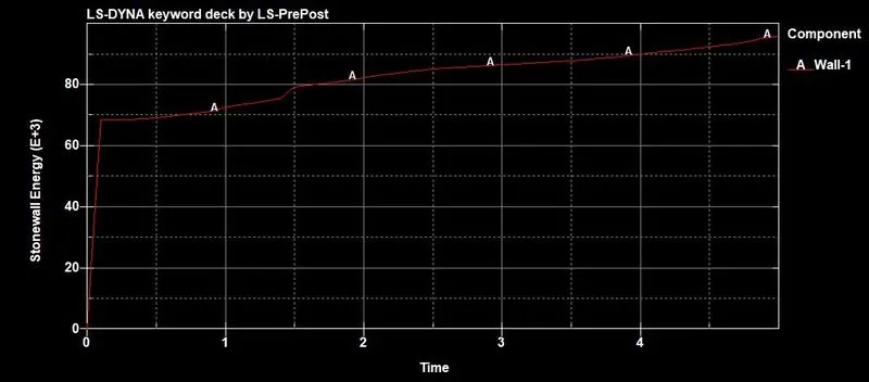
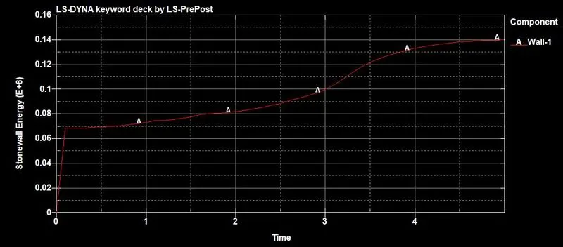
Fig 7: Stonewall Energy plot for 1.2mm box Fig 8: Stonewall energy plot of 1.5mm box
The drop in the final total energy is also reflected in the energy ratio plot (final total energy/initial total energy) shown in Fig 9 and 10.
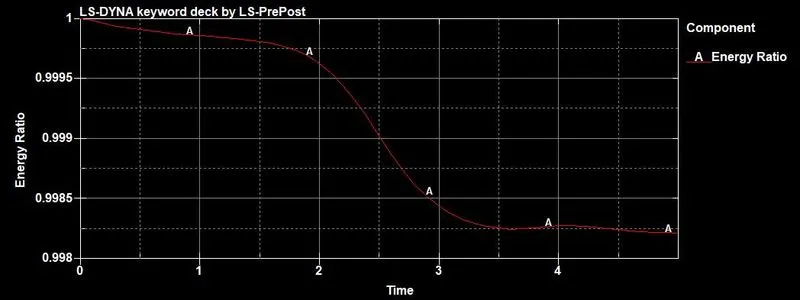
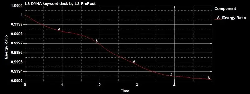
Fig 9: Energy Ratio plot of 1.2mm box Fig 10: Energy Ratio plot of 1.5mm plot
The impact with the wall generates a maximum force of 4.55e05N at 0.2ms and 4.74e05N at 0.5ms for the 1.2mm and 1.5mm boxes respectively.
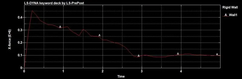
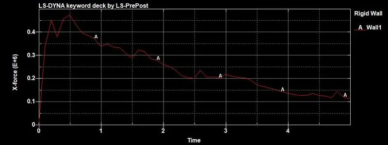
Fig 11: Rigidwall Force of 1.2mm box Fig 12: Rigidwall Force of 1.5mm box
The analyze the forces developed in the centre of the crashbox, a section was defined as shown in Fig 14 and 15. The maximum cross-sectional force in the X-direction developed here was 1.75e05N and 1.95e05N for the 1.2mm and 1.5mm boxes respectively.
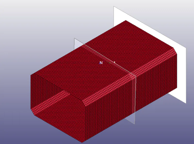
Fig 13: Section plane defined for results
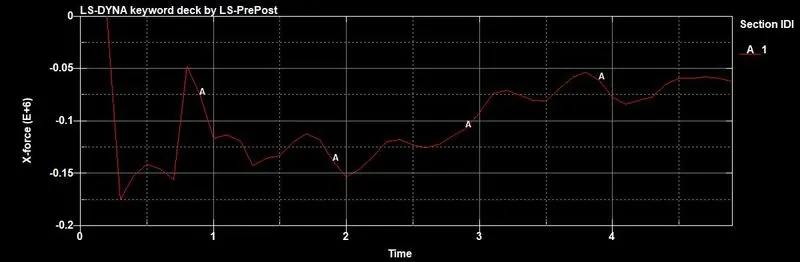
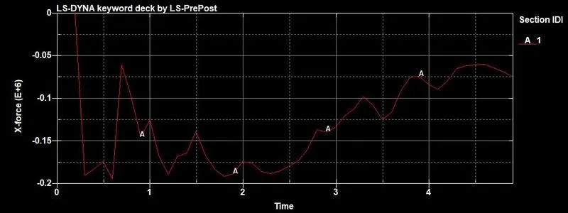
Fig 14: Section force of 1.2mm box Fig 15: Section force of 1.5mm box
The acceleration in the X-direction at node 7527 was plotted. This node accelerates to a maximum of 8.31mm/ms2 (at 0.8ms) and 7.21mm/ms2 (at 0.8ms) for the 1.2mm and 1.5mm boxes respectively. The plots show the acceleration value flickering between positive and negative values indicating that at times, the node is actually decelerating.
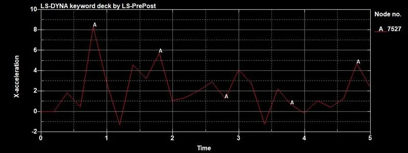
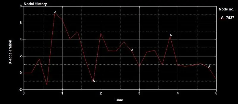
Fig 16: Acceleration plot of 1.2mm box Fig 17: Acceleration plot of 1.5mm box
The 1.2mm box develops a stress of 1450MPa along its length while the 1.5mm box develops only 1314MPa. The greater thickness of elements increases the cross-sectional area of the box elements and reduces the stress in them.
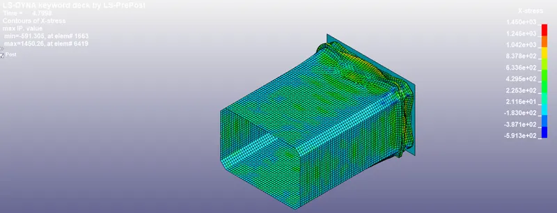
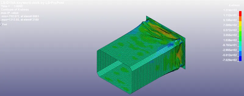
Fig 18: X-stress in 1.2mm box Fig 19: X-stress in 1.5mm box
To get the longitudinal and lateral strain, Fringe>Infin>x-strain, y-strain was used. This option provides an approximate strain output. The longitudinal strain in the box is very low - 6.284e05 and 1.365e04 in the 1.2mm and 1.5mm box respectively. The lateral or y-strain values of the same are 0.3428 and 0.2631 respectively. The strain developed is plastic since the stresses developed are way above the yield point.
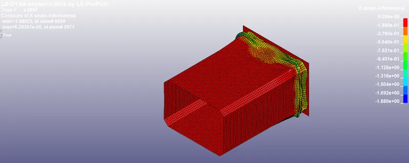
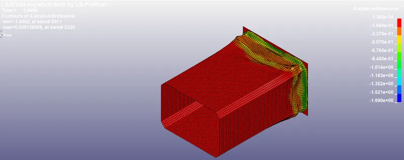
Fig 20: X-strain in 1.2mm box Fig 21: X-strain in 1.5mm box
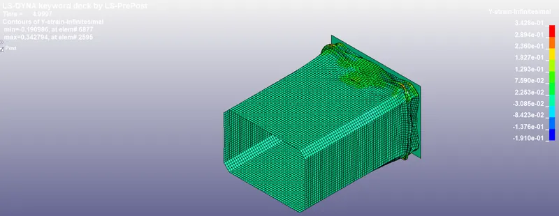
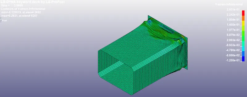
Fig 22: Y-strain in 1.5mm box Fig 23: Y-strain in 1.5mm box
Conclusion: From the energy plots in Fig 5 and Fig 6, it can be observed that the box with 1.5mm thickness absorbs 8e05 N-mm of energy more than the box with 1.2mm thickness. The acceleration of the selected node is also lower in case of the box with 1.5mm thickness. Since the function of the crashbox is to absorb as much of the energy of the crash as possible and slow down the intrusions in the car, the box with 1.5mm thickness will be a better choice for use. Further improvements can be made to the energy absorption behaviour by introducing geometric discontinuities like bird beaks, corner holes and surface beads in the box.