Week - 4 - Crash Box Simulation
Simulation Of Crashbox Crash the Rigid Wall Using LS Dyna
Objective : Understand the crashbox simulation when it crash the Rigidwall using LsDyna.and validate the results of thickness 1.2mm and 1.5mm using the unit system of gm-mm-ms.
About CrashBox: Crashbox is important structural member in the Automotive vehicles which can absorb the dynamic energy during collison.usually crashbox made of alumnim and steel .
Crash-boxes play an important role in automotive parts. It is not only to protect car occupants and external pedestrian safety, reduce the degree of damage effect, but also to reduce the damage to vehicles and other components. It can also reduce the repair cost of vehicle in the crash occurred.
Crashworthiness can be defined as the capability of an automobile to shield its occupants from serious injury or death in case of accidents of a specified proportion and provides a measure of the ability of a structure to protect the occupants in survivable crashes.
Understand the details to simulate the Crashbox.
In this assignment, the student needs to simulate a crash test for a crashbox for which mesh is given. A crash box is a highly energy absorbing structure that crashes on application of loads and reduces impact on other components nearby. A full-fledges Crashbox is a highly sophisticated design but in this case we will go with a rectangular channel which can thought of as the most simple crashbox.
Here are the different assumptions and information required:
- The crash box should crash into a rigid wall created using *RIGIDWALL_ keyword. Check the manual to understand and create a rigid wall.
- Material for the crashbox is steel. The simulation needs to be started using elastic material to verify its correctness and later a nonlinear material card data will be provided. Thickness of the crash box is 1.2mm.
- Initial velocity for the crash box should be around 50 kmph.
- The units system to be used is gm-mm-ms.
- The simulation should satisfy either of the two situations - (1) It crashes on the rigid wall and rebounces completely or (2) it buckles and folds in the axial direction so as to come in self-contact.
- Once the simulation is completed and results as asked for below is collected, run another simulation by increasing the thickness of the crash box from 1.2 to 1.5mm.
Deliverables:
- Input .k file and output files (d3plot, glstat, sleout, rcforc)
- Animation of the final simulation.
- Cross-sectional force generated in the middle of the crashbox (along its length).
- Acceleration plot of a node in the middle of the crashbox (along its length).
- Maximum directional stress and strain along the length of the crashbox (X strain, Y strain etc).
- Plot of all energies (total, internal, kinetic, hourglass, sliding).
- Compare the accelerations and stress/strain plots of 1.2/1.5mm crash boxes.
Importing the model keyword file after opening the LS Pre-post then setting the model as per the requirement. The meshed model through file →import or open the folder.
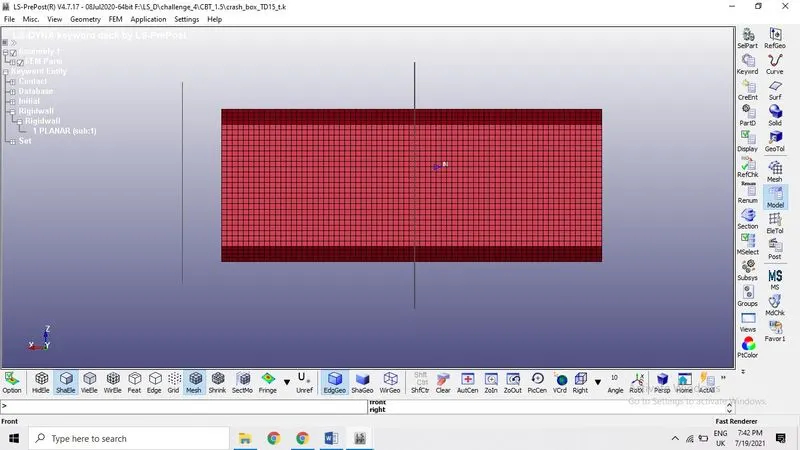
Material set-up: MAT-024 or MAT_ Piece wise_ linear _ plasticity from the keyword manager
As we can see the image, the model with mesh position using the auto center option so that we can see the image properly. We consider mesh only in the setup so we can delete the solid in the model.
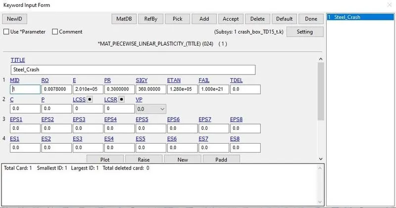
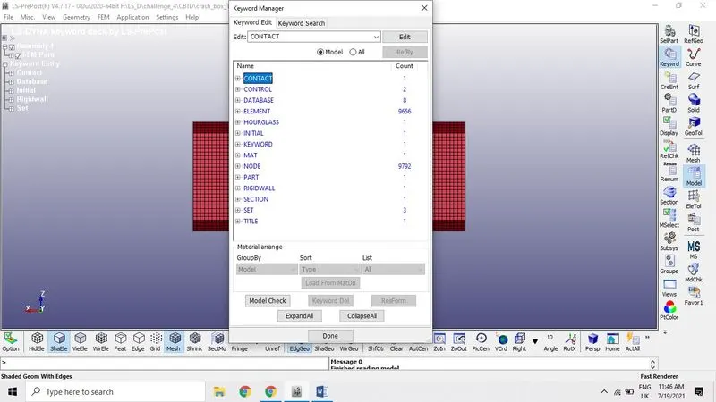
Now open the keyword manger by clicking on the model icon then assign the material by opening the keyword manger, open the MAT file to assign the material property to the model from exiting materials. There are many material type available here but *MAT_024* is the piecewise Linear plasticity which is suitable for robust materials of linear plasticity also suitable for elastoplastic materials.(strain –rate dependency) Which is suitable for viscoelastic material behavior with arbitrary stress .
Keyword Manger > select MAT> 024 > keyword input form
Part and Section cards:
In this section, the element formulation, integration rule, nodal thicknesses, and cross sectional properties are defined. All section identifiers (SECID’s) defined in this section must be unique; that is, if a number is used as a section ID for a beam element, then this number cannot be used again as a section ID for a solid element
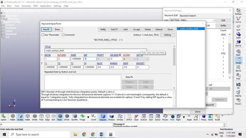
Created FE section shell elements with thickness 1.2mm, 1.5mm using LS Dyna keyword manger → Model (All) → Section
We need to run the simulation using thickness 1.2 and 1.5 mm.
Rigid wall
Rigid wall definitions have been divided into two separate sections, PLANAR and GEOMETRIC. Planar walls can be either stationary or moving in translational motion with mass and initial velocity. The planar wall can be either finite or infinite. Geometric walls can be planar as well as have the geometric shapes, such as rectangular prism, cylindrical prism and sphere.
Add frictional energy calculation for constraint-based rigid walls. Keyword entity→ rigid wall → selecting the option planar or node. After creating the rigid wall move it away from the crashbox of distance required using the translation option. Rigid wall is hit by the crashbox with a velocity of 13.88 mm/ms.
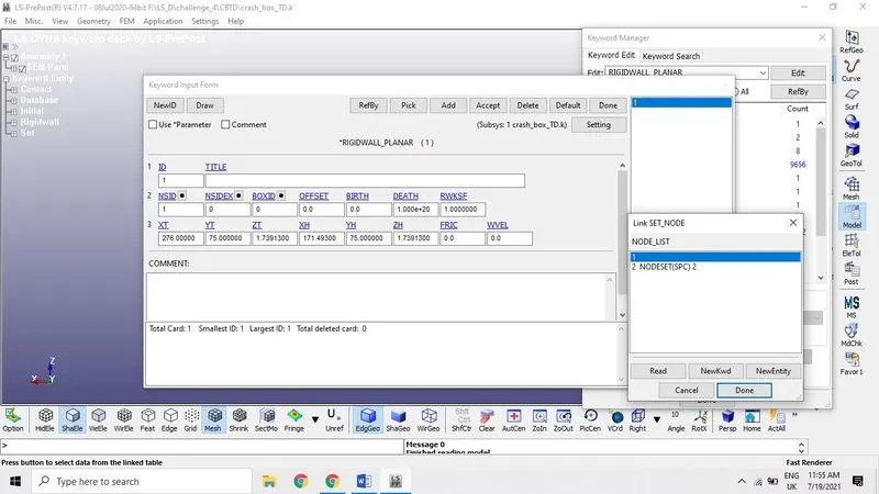
Initial velocity of the Crashbox:
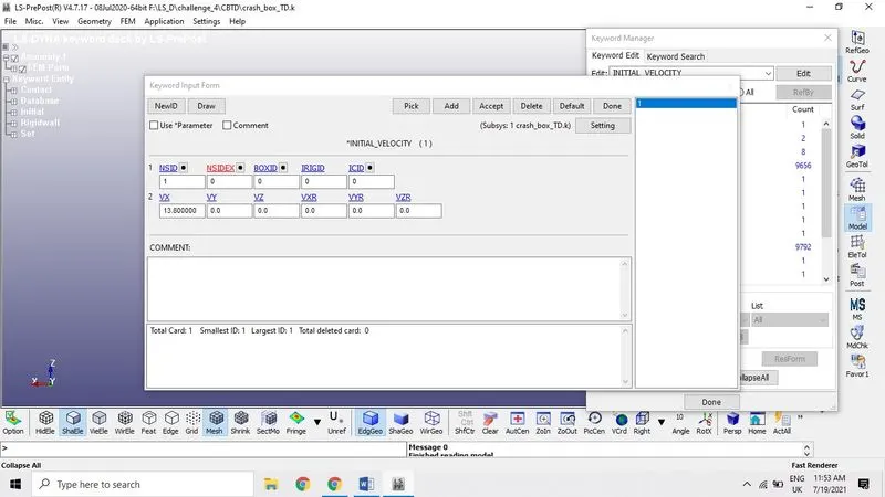
The intial velocity card set up here with 13.8 mm/ms which is in the direction rigid wall about X-direction here. And also set the node set ID of the part
Control Termination: To stop the calculation at particular time
The keyword *TERMINATION provides an alternative way of stopping the calculation before the termination time is reached. The termination time is specified on the *CONTROL_TERMINATION input and will terminate the calculation whether or not the options available in this section are active.
Contact card:
Most of the control contacts are single surface contacts for crash and impact type. A self-established contact in our model as there only single surface contact card. We have one surface it automatically recognize the surface elements.
Model checking :
Before we go to the solver analysis or post-processing we need to verify the keyword manger by going through the model check option. We need to clear-up the errors if any present in the keyword After saving the keyword file to run the simulation in Lsrun.
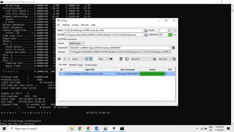
Here we can see the Normal termination.
Animation file of crashbox simulation.
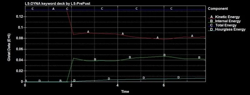
Energy Plot for shell thickness of 1.2 and 1.5
Plotting graphs: After observing the animation, now we can plot the graph using energies and contact forces using ASCII plot in the post processing tab.
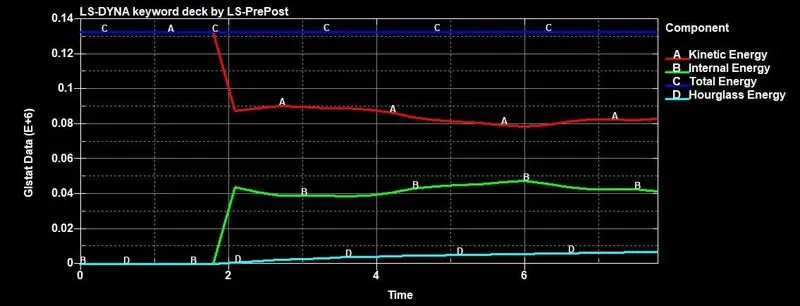
The above energy plot shows the behavior of the
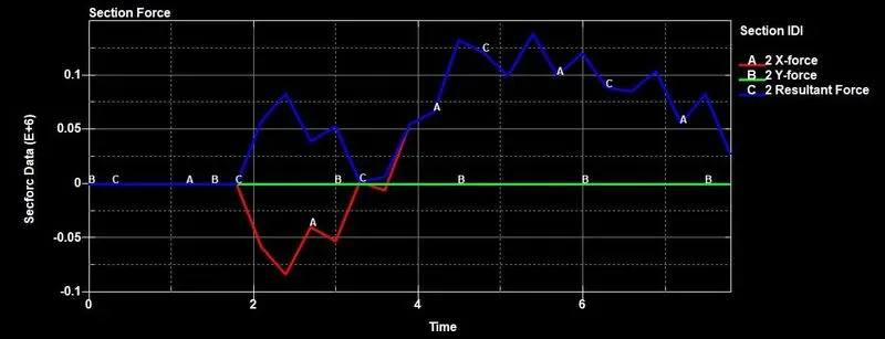
 Comparison of X-force, Y-force and resultant both 1.2 and 1.5 both are showing the same variation
Effective stress (V-M) 1.5mm thickness of crash box:
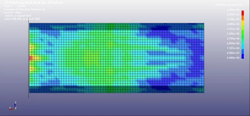
Minimum=0 at element# 9657. Max= 698.478 at element #1500
Effective stress (V-M) 1.2mm thickness of crash box
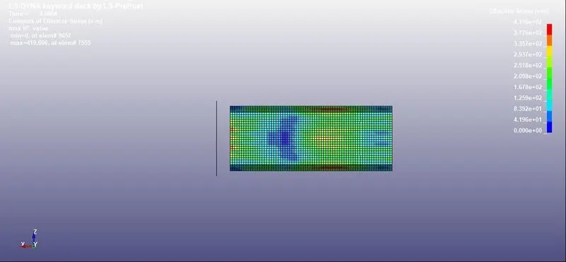
Minimum =0 at element # 9657 and Max=419.606, at element#7555
Effective strain (V-M) 1.5mm thickness of crash box:
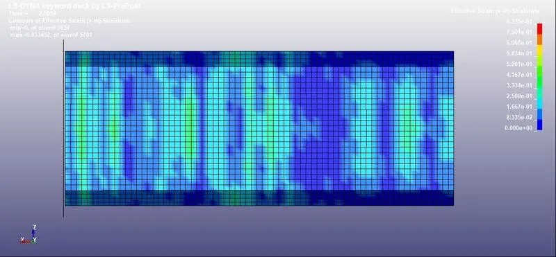
Minimum =0 at element # 9657 and Max=0.8834, at element #5701
Effective strain (V-M) 1.2mm thickness of crash box:
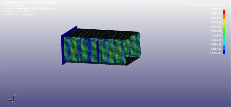
Minimum =0 at element # 9657 and Max=0.445801, at element #18
X-stress 1.5 and 1.2mm thickness
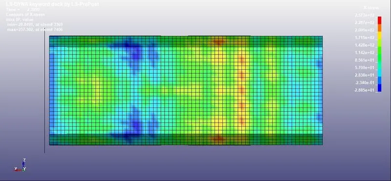
Minimum =-28.84, at element # 3369, and Max=257.302, at element #7406
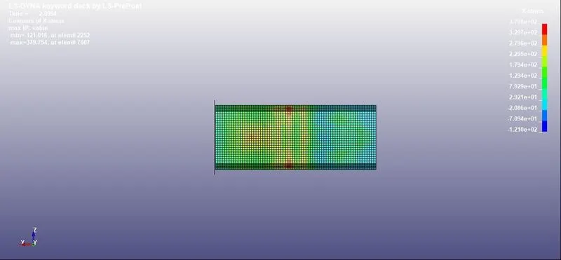
1.2mm thickness Minimum =-121.015, at element # 2252, and Max=379.754, at element #7607
Y-stress 1.5 and 1.2mm thickness
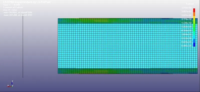
1.5mm thickness Minimum =-94.8621, at element #6286, and Max=351.288, at element #4393
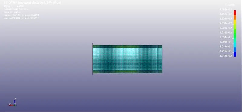
1.2mm thickness Minimum =-134.184, at element #4399, and Max=436.079, at element #5391
X-Strain 1.2 and 1.5mm thickness of crash box
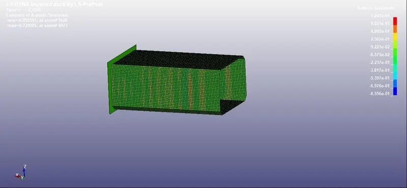
1.2mm thickness Minimum =-0.855, at element #5620, and Max=0.724, at element #6073
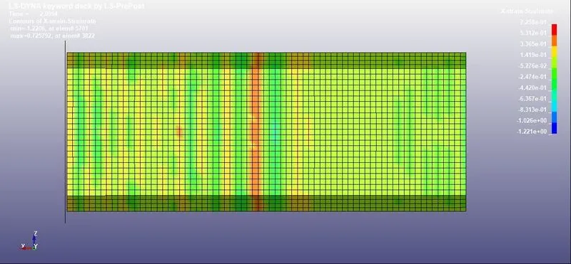
1.5mm thickness Minimum =-1.2206, at element #5701, and Max=0.7257, at element #3822
Y-Strain 1.2 and 1.5mm thickness of crash box
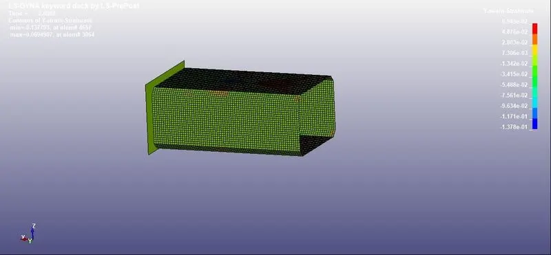
1.2mm thickness Minimum =-0.1337, at element #4657, and Max=0.06949, at element #3064
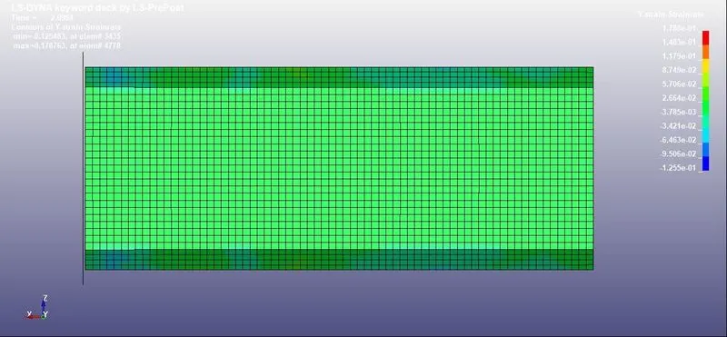
1.2mm thickness Minimum =-0.125, at element #3435, and Max=0.1787, at element #4778
Conclusion
- Crash box Simulation keyword preparation is done according to the given requirement.
- Animation of the crash box recorded and run the simulation using LS-Run without any error termination
- Simulation is done for both 1.2 mm and 1.5mm thickness of the crash box.
- Plotted graphs for output energies of crash box