Week 4 - CHT Analysis on Exhaust port
Exhaust Port Simulation (CHT - Conjugate Heat Transfer)
Objectives:
- Give a brief description of why and where a CHT analysis is used.
- Maintain the y+ value according to the turbulence model and justify the results.
- Calculate the wall/surface heat transfer coefficient on the internal solid surface & show the velocity & temperature contours in appropriate areas.
- How would you verify if the HTC predictions from the simulations are right? On what factors does the accuracy of the prediction depend on?
Theory:
Conjugate Heat Transfer corresponds to the combination of heat transfer in solids and fluids (Conduction and Convection). It is mostly seen in processes like Heat Sink, Battery Cooling and Airflow over the solid object for cooling. When heat transfer takes place between solids and fluids, CHT analysis can be done to find the optimum result.
CHT Analysis is used in processes which involve variations of temp. within solids and fluids, due to thermal interaction between them.
CHT Analysis on Exhaust Manifold:
- Import the given 3D model into Spaceclaim.
- Extract fluid volume by selecting 4 inlet ports and 1 outlet port.
- Move the fluid volume and solid volume into a new component. Delete the (old) empty components.
- Be sure to check Share Topology option in the left pane (Properties) as well as in “Workbench” tab à Share option.
- Open Mesh Module. Create Named Selections:
- 4 inlets
- 1 outlet
- Outlet wall for convection
- In Case 1, create a baseline mesh.
- In Case 2, change element size to 10mm. Add an inflation layer with total thickness of 5mm to the outer wall.
- Open Fluent next. Materials: Air (Fluid) and Aluminium (Solid)
- Boundary Conditions:
- Inlet Velocity:
- Inlet Temperature: 700K
- Outer wall Convective Heat Transfer Coefficient: 20 W/m2K
- Create Contour for Temperature from “Results” tab. Assign Animation accordingly from “Solve” tab.
- Solve the problem for 150 iterations.
Results:
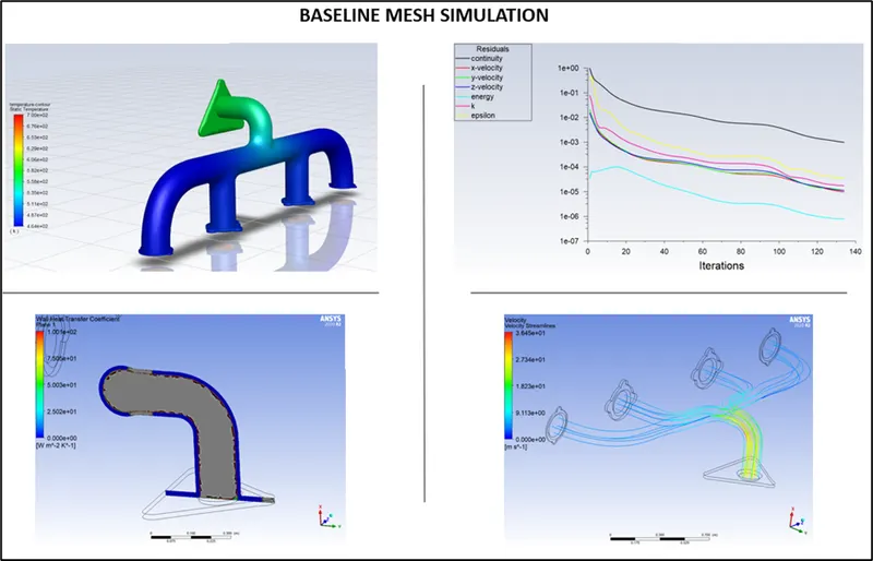
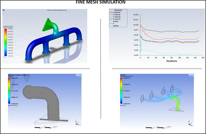
Conclusion:
From the Velocity Streamline images, we can see that the Velocity is maximum at Outlet. This is because of Mass Conservation. There are 4 inlets and just 1 outlet, and all have the same flow area, therefore, the flow rate (Q = AV) will be higher at the outlet because (V1+V2+V3+V4 = Vo)
Wall Heat Transfer Coefficient is a quantity that is only calculated at the walls along which the fluid flows.
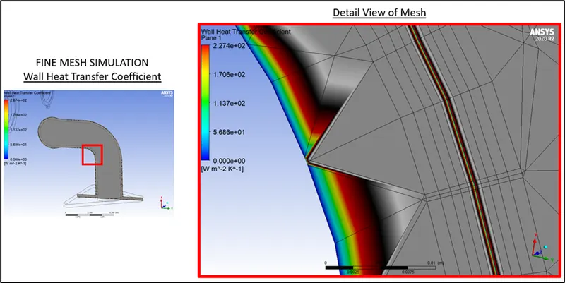
From the images, it can be seen that by refining the mesh and adding inflation layers, we can achieve a smooth plot with distinct bands indicating various regions.
Q. How would you verify if the HTC predictions from the simulations are right? On what factors does the accuracy of the prediction depend on?
A. Nusselt Number Nu = hL/k
where, h = Convective heat transfer coefficient
k = Conductive heat transfer coefficient
L = Characteristic Length
We know that the Nusselt Number is a function of Reynolds Number, which is a function of Flow Velocity. Hence, Heat Transfer coefficient is directly proportional to flow velocity. And that is corroborated by the simulation results as shown above. Hence, the simulations are accurate.
The main factors affecting the prediction are the Mesh parameters. The quality of mesh, size, inflation layers etc. all play a crucial role in evaluating the results.