Week-4 Challenge WOT Condition Part-2
- What is the difference between the mapped and dynamic model of engine, motor, and generator? How can you change the model type?
- How does the model calculate miles per gallon?. Which factors are considered to model fuel flow?
- Run the HEV Reference application with WOT drive cycle. Change the grade and wind velocity in the environment block. Comment on the result.
- Keeping all the other parameters the same, compare the simulated results of hybrid and pure electric powertrain.
Solution 1:-
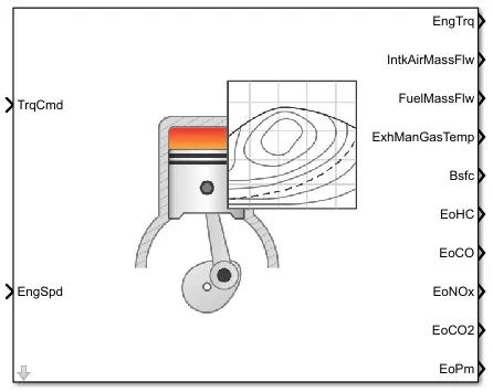
Mapped Engine Model
Mapped engine signifies macro engine behavior used to calculate the function of the defined load and measure the engine speed.
Brake torque, fuel flow, air mass flow, exhaust temperatures, and emission are calculated in the mapped engine.
Mapped engine model uses a steady-state lookup table to characterize engine performance. The table provides overall engine characteristics which include actual torque, fuel flow rates, BSFC, and exhaust emissions.
These are generally used when the user has engine data form a dynamometer or for quasi-steady-state engine simulations.
Mapped motor
The mapped block implements mapped motor and drive electronics in the torque control mode. The output torque tracks the torque reference demand and includes a motor-response and drive- response time constant.
The mapped block assumes that the speed fluctuation due to mechanical load does not affect the motor torque tracking.
We can specify from the following :
Port configuration — Input torque or speed.
Electrical torque range — Torque speed envelope or maximum motor power and torque.
Electrical loss — Single operating point, measured efficiency, or measured loss. If you have Model-Based Calibration Toolbox™, you can virtually calibrate the measured loss tables.
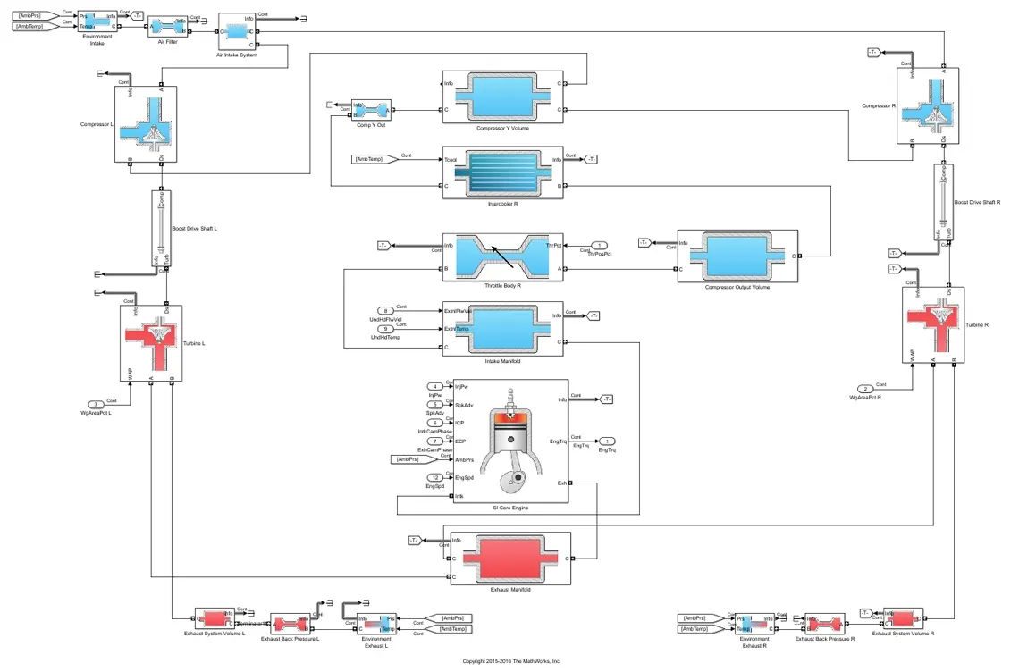
Dynamic engine model
Dynamic engine model decomposes the engine behavior into engine characteristics that are separated into lower-level components. By combining components in this way, the models capture the dynamic effects.
It can be used to analyse the impact of individual engine components on the overall performance. Dynamic models are used to design control, estimator and diagnostic algorithm that depends on the dynamic subsystem states. Eg; in closed loop AFR control Algorithm development.
Procedure for changing the model type
Step 1: - Go to powertrain blockset
Step 2: - Select the desired powertrain blockset type. Blocksets include Pure electric, Hybrid, IC engine.
A new window will open showing the Simulink model.
Another window file will show the path and workflow.
We have to select or proceed for the passenger block and switch the EV motor to generator.
Right-click to select MotorGenEV mapped or dynamic.
Solution 2: -
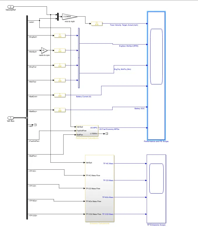
In the visualization subsystem we can select performance calculation and we can optimize vehicle level performance , battery state of charge(SOC), fuel economy and emission results that are used for powertrain machining and component analysis.
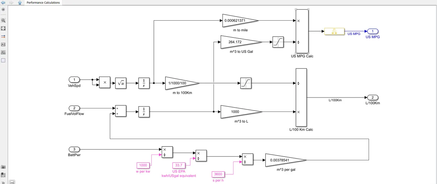
Vehicle Speed and Fuel Flow: -
Vehicle Speed and fuel flow are important factors in calculating miles per gallon. In this the flow is converted m^3. m^3 is used for US Gallon.
Vehicle speed calculates the distance traveled.
Miles per gallon: It is calculated using inputs of vehicle speed, fuel flow, and battery power
Solution 3: -
For the Simulation of the HEV model with Wide Open Throttle condition, we follow the steps.
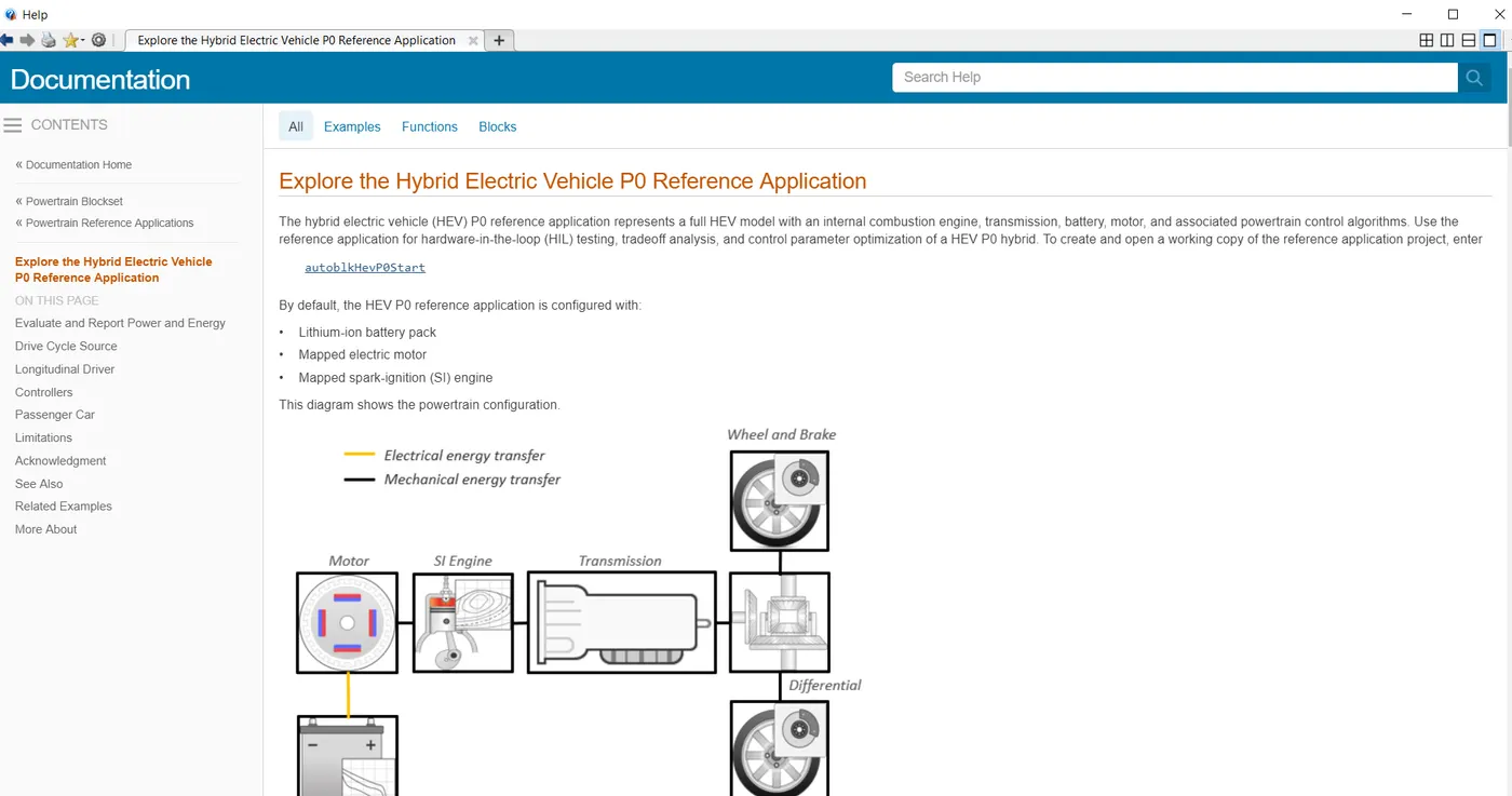
Step1: We open the powertrain block set by either using the help menu or by typing ‘autoblkHevP0Start’ in the command window.
Step 2: We select the ‘Hybrid and electric vehicle reference application project’.
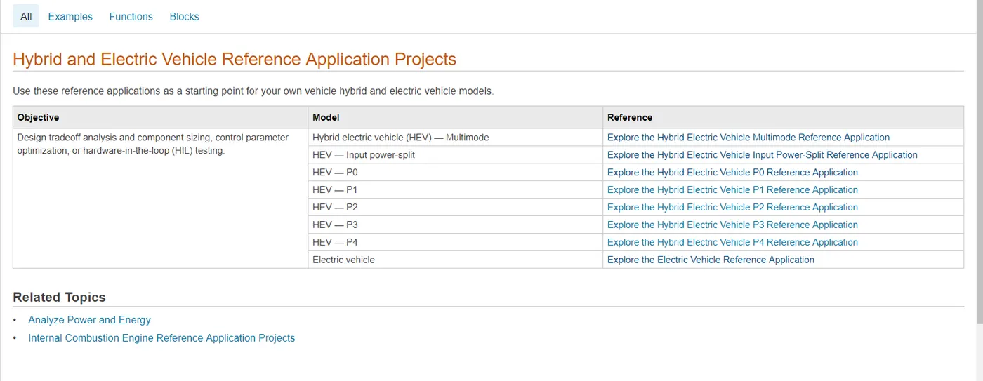
Step 3: From the reference application of vehicle hybrid and electric vehicle model select ‘HEV- P0 . Explore the hybrid electric vehicle reference application. We see the details of HEV reference applications. We select ‘autoblkHevP0Start’.
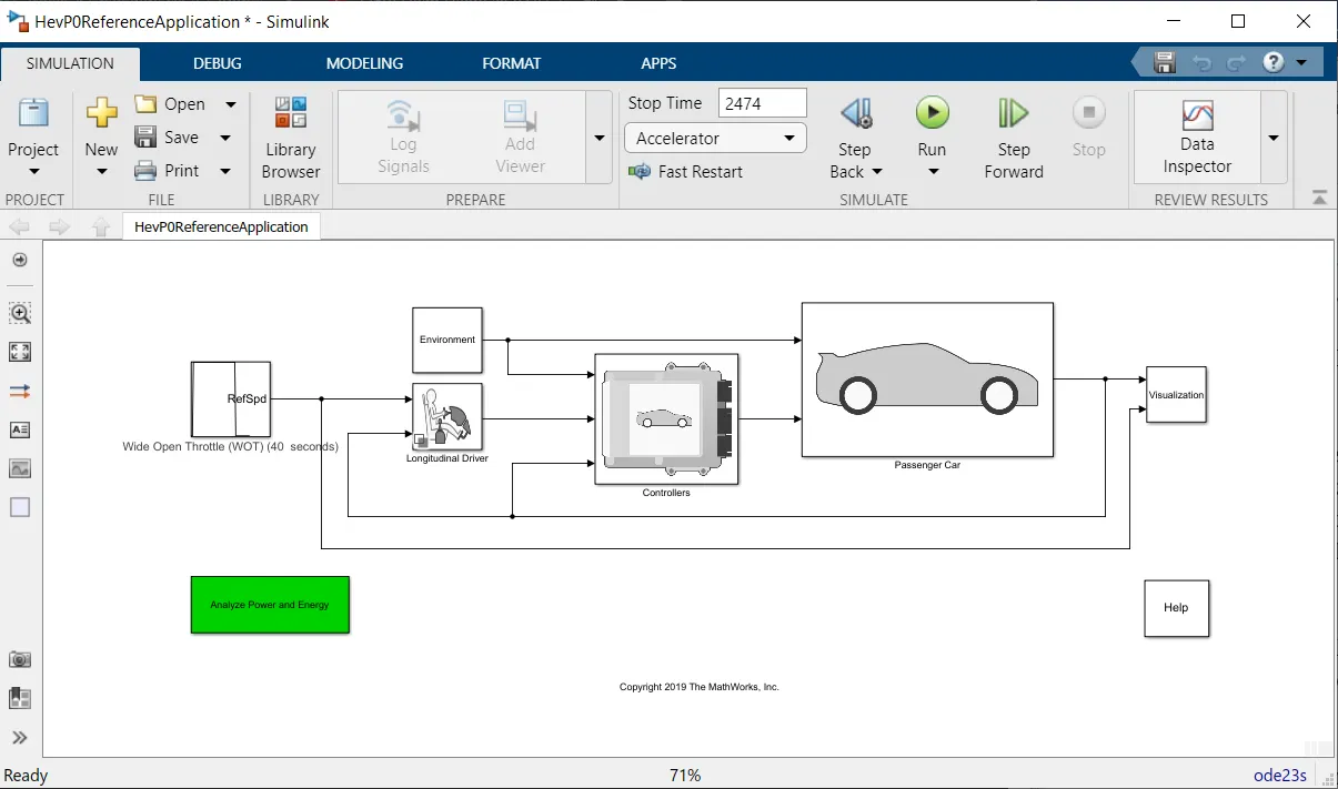
The hybrid electric vehicle (HEV) represents the full HEV model which includes an internal combustion engine , transmission ,battery ,motor and the associated power control algorithm.
The HEV P0 has the following configurations:
Lithium ion battery pack
Mapped electric motor
Mapped spark ignition (SI) engine
Step 4: Double-click on the drive cycle block for setting the drive cycle.
Set the drive cycle to WOT (Wide open throttle)
Step 5: Change ode23tb(stidd/TR-BDF2) to ode23s(stiff/Mod.Rosenbrock)
Step5: Change the grade and the wind velocity by double-clicking the environment block
To check the simulated result double click on the
visualisation block and double click on the performance and FE scope.
A graph will popup showing the trace velocity , engine speed ,motor speed ,engine torque ,battery currentA), Battery SOC , fuel economy.
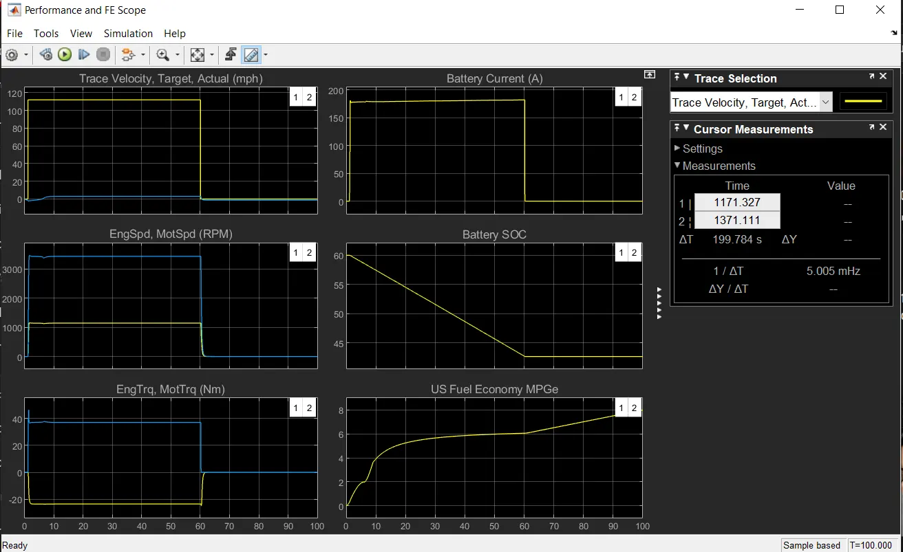
Electric plant Average efficiency = 0.82
Engine Plant average efficiency=0.00
Drivetrain efficiency = 0.56
Solution 4:
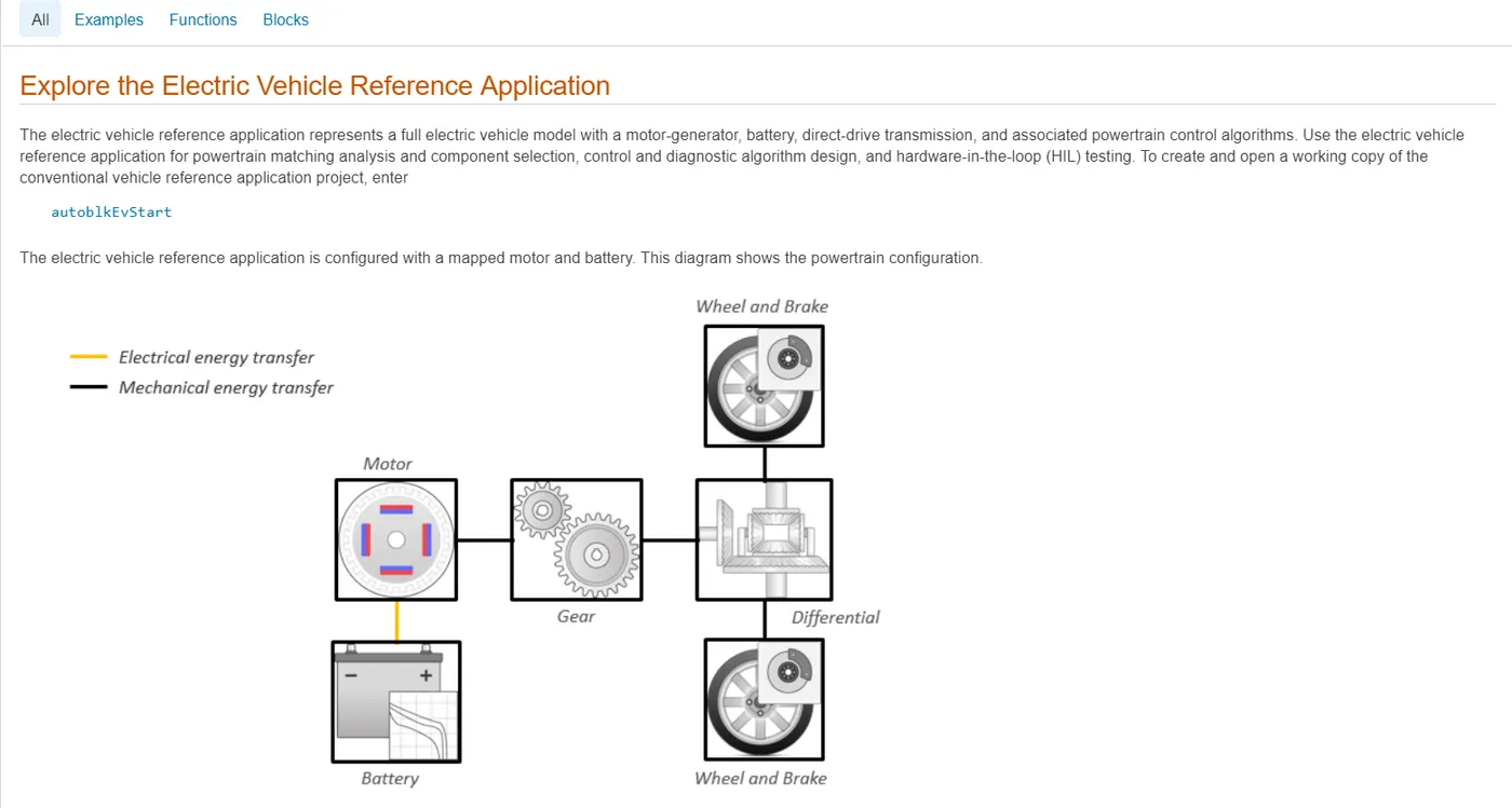
The electric vehicle reference application represents a fully electric vehicle model with a motor-generator, battery,direct-drive transmission, and associated powertrain control algorithms. To create and open a working copy of the conventional vehicle reference application project ‘autoblkEVStart’, enter by using the command window.
The electric vehicle reference application is configured with a mapped motor, battery.
Step1: Double click the drive cycle block for setting the drive cycle.
Follow the same steps as in HEV reference application for changing the value and setting of drive cycle.
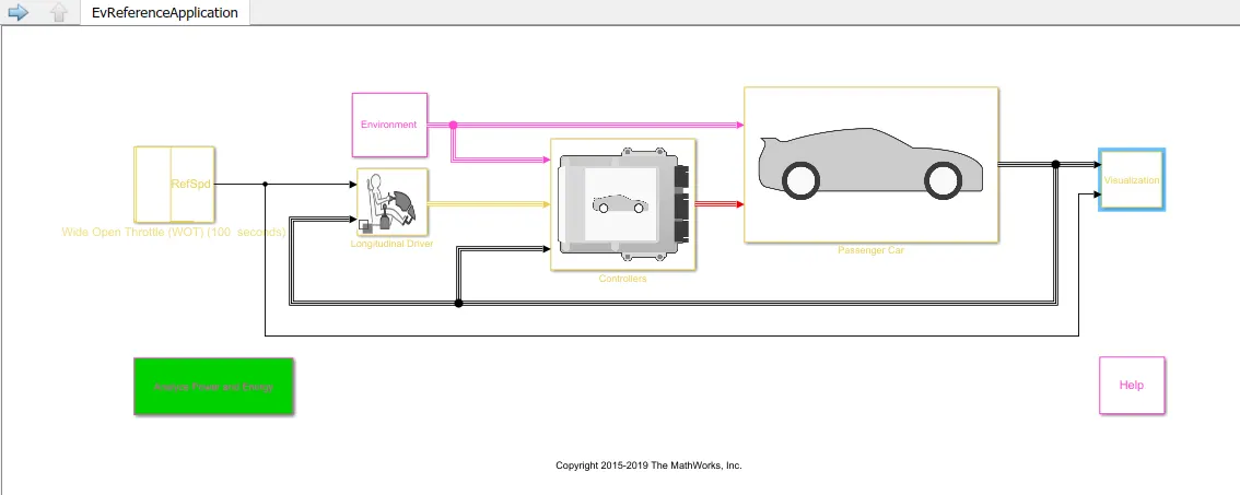
Graph showing the trace velocity,motor speed , Motor torque , battery current, battery SOC , US MPG
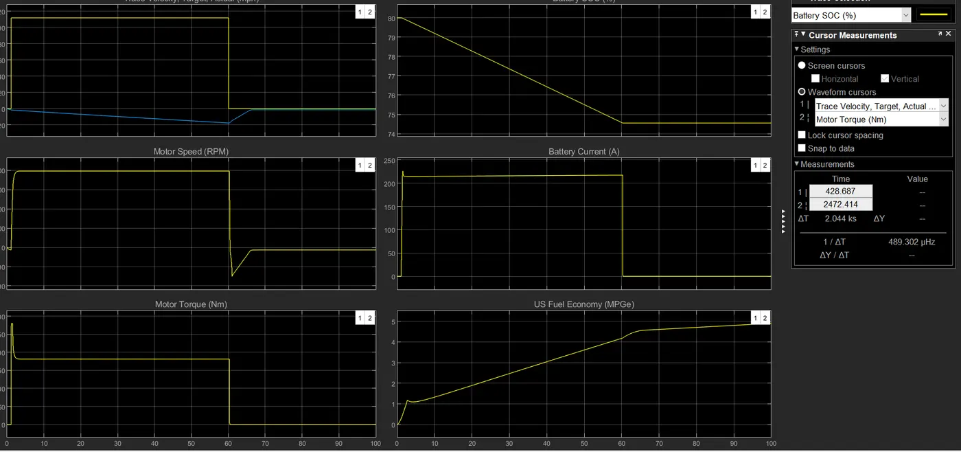
According to the graph the Battery SOC is dropping from 80% to nearly 74% and staying constant. The Battery Current is first increasing and then decreasing. Fuel Economy is also increasing.
HEV Results
Electric plant efficiency =0.82
Engine plant Efficiency=0.00
Drivetrain Average Efficiency= 0.56
EV Results
Electric Plant Efficiency=0.92
Drivetrain Average Efficiency =0.00
From the comparison done between hybrid vehicle and pure electric vehicle, the efficiency of pure electric is higher. Also the drivetrain average efficiency also decreased in pure electric vehicle