Week 4 Challenge : CFD Meshing for BMW car
Aim:
For the given model, check and solve all geometrical errors on half portion and Assign appropriate PIDs. Perform meshing with the given Target length and element Quality criteria. After meshing the half model, Do symmetry to the other side.
Objective:
- Target lengths for the different parts of a model are as follow:
- Body - 3 mm
- Lights - 4 mm
- Grills - 1 mm
- Rims and Tyres - 2 mm
- Optical Rear view mirror - 2 mm
- Window - 2 mm
- Silencer - 3 mm
- Logo - 1 mm
Procedure:
Steps involved are given below:
- In first step we cut the geometry in half, cause working on full geometry consumes time and efforts which later on we will create symmetry of cleaned half.
- Now we do the topo which reduces few single cons. After that we move on part by part of our car geometry starting with front grill and headlight which we can do by isolating the geometry.
- After the isolating we start working on them like deleting the triple cons, extra cut, single cons, and also we have to check where the geometry is getting impractical (which cannot possible practically) we can see below with refrences pof images pre and post cleanup of geometry of grill
Pre-cleanup grills geometry:
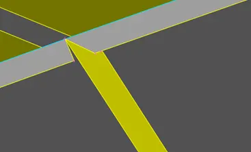

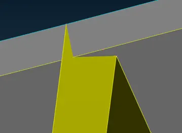
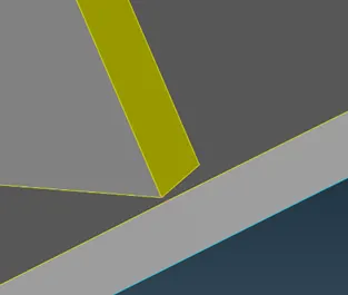
Fig 1: errors, and tripple conns in grill geometry before cleanup
Now we can see below the post cleanup geometries images ;
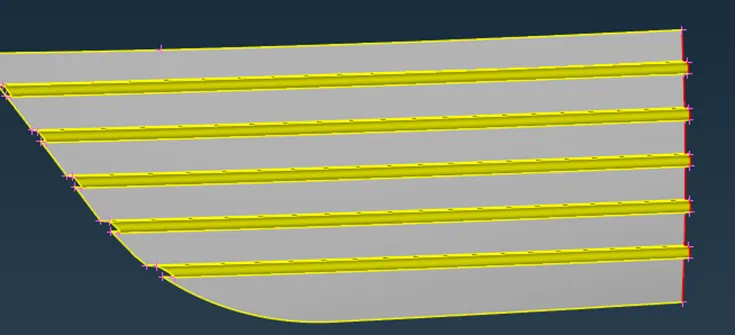
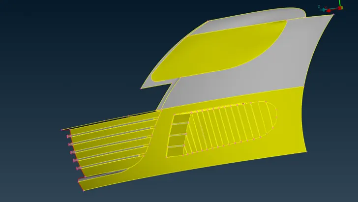
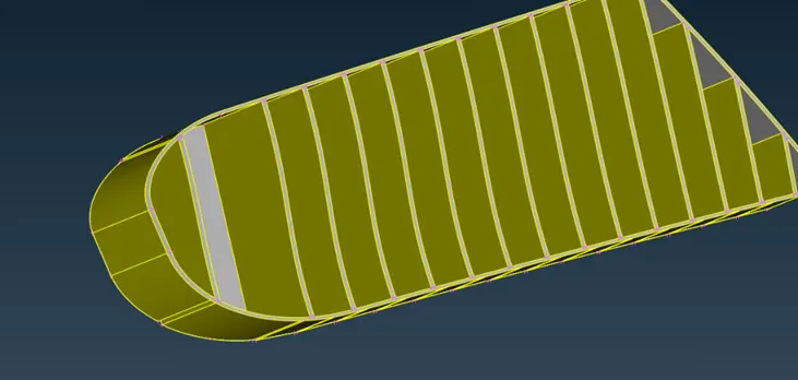
Fig 2. Post cleanup grill geometries(no triple cons and extra cuts)
- Like wise there are many faults in whole car geometry but by using the options like cut, extend, intersect, hot points insert, hot points delete, universal delete etc. we get rid of those errors and We can see those cleared differences in images below
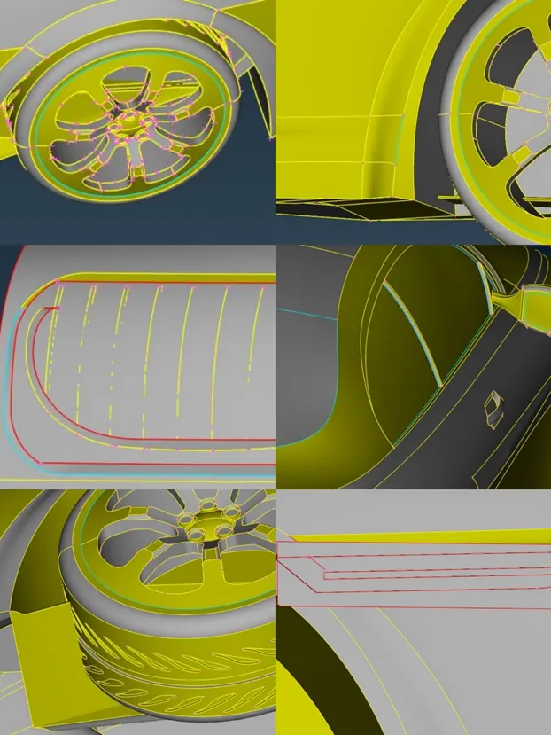
Fig 3. Errors in overall body
Now below we can see the cleanup done by us on body and post cleanup results
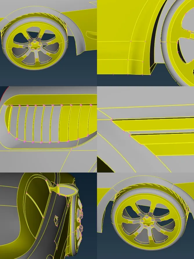
Fig 4. Post cleanup body geometry
- We above done the topo cleanup of whole geometry after cleaning those we move next to next part which is assigning the PID to different parts of body which make our work easy to work on particular geometry. We can see those below
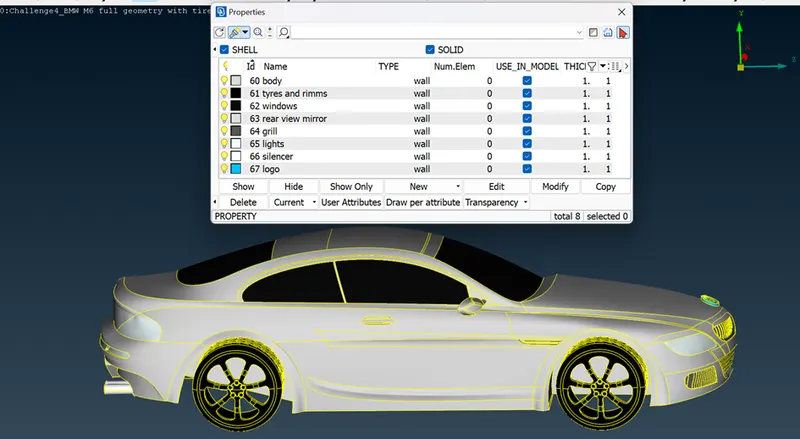
Fig 5. PIDs assigned
- Now as our whole geometry get cleaned, PIDs get assigned now we are move on to check the mesh parameters like, how much length assigned to which part and according to that we have to clean the cons/hot points whose distance from neighbour cons/ hot points are less than minimum length of mesh but for that first we have to measure and check the geometry manually, so by isolating every geometry one by one we measure the values using measuring tool which we can see below in images
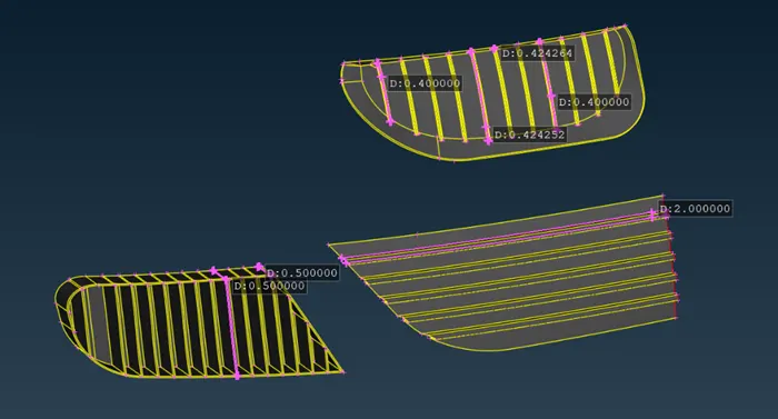
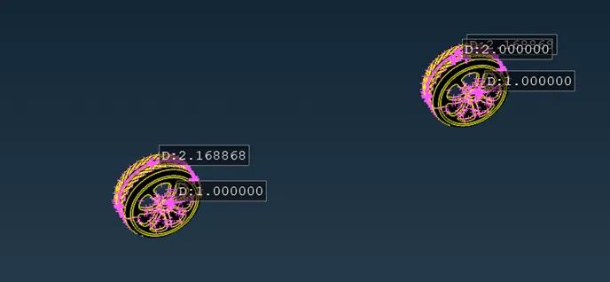
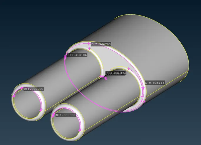
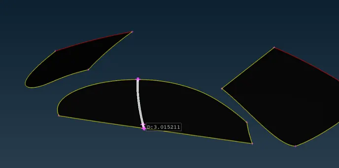
Fig 6. Closer measurements of isolated PID
- As we measure these doubtful geometries if we find any cons closer to each other we remove any one con by using cut option and right mouse click but while doing this we have to keep in mind that the co we remove shouldn’t have major effect on geometry such as we don’t have to remove the cons which are associated with any curved surface.
- So after cleaning up the closer cons and points now lets move to mesh, here we have to follow the quality criteria means create the mesh which shouldn’t exceeds the values of quality criteria. So here also we have to do the same like we done before isolate the particular PID, apply the quality criteria and apply the mesh just like shown below.
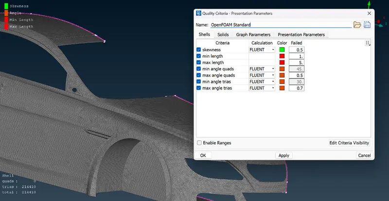
Fig 7. Body mesh and quality criteria (target length 3mm)
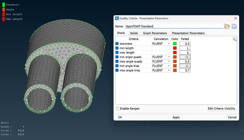
Fig 8. Silencer mesh and quality criteria (target length 3mm)
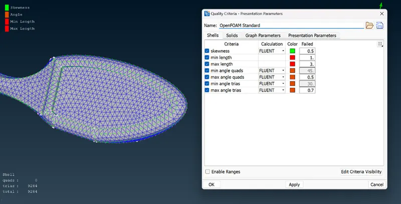
Fig 9. Mirror mesh and quality criteria (target length 2mm)
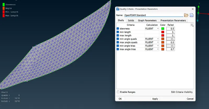
Fig 10.Light mesh and quality criteria (target length 4mm)
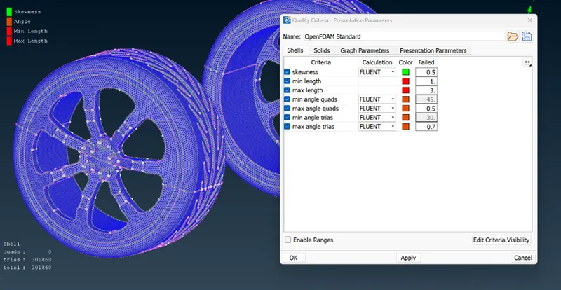
Fig 11. Tires and Rims mesh and quality criteria (target length 2mm)
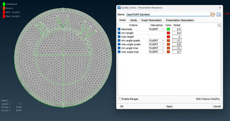
Fig 12. Logo mesh and quality criteria(target length 1mm)
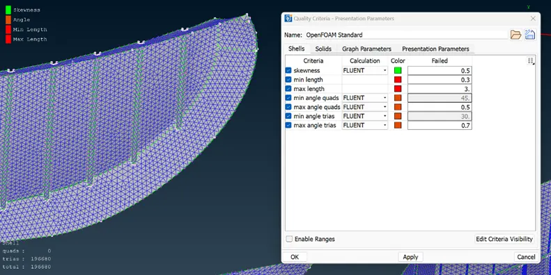
Fig 13. Grill mesh and quality criteria (target length 1mm)
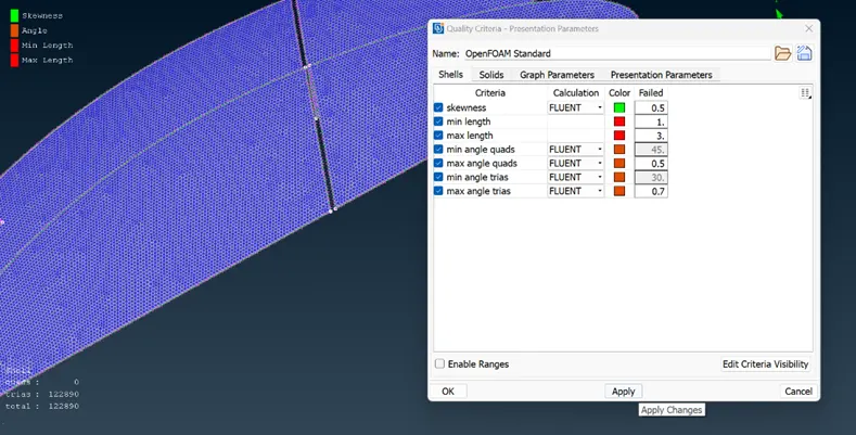
Fig 14. Window mesh and quality criteria (target length 2mm)
While doing mesh for each and every part we get the offs, offs are those elements of mesh which doesn’t fall in quality criteria or which exceeds the criteria values(all above images are post offs cleanup). We have to check those offs and solve those using the options like reconstruct, improve, move, hot points and cuts. These offs are only visible in hidden mode so we have to turn off the shadow mode and on the hidden mode. Offs are mostly occurs because of extra cons and points which we missed during the topo clean-up.
- Now as we clean our offs and mesh is good to go we now move forward to do the symmetry of the car half cause this is right time to do as we have cleaned topo and cleaned mesh so now we just have to copy that part to another side. For that we follow below steps :
- first we go to transform in menu bar of Ansa
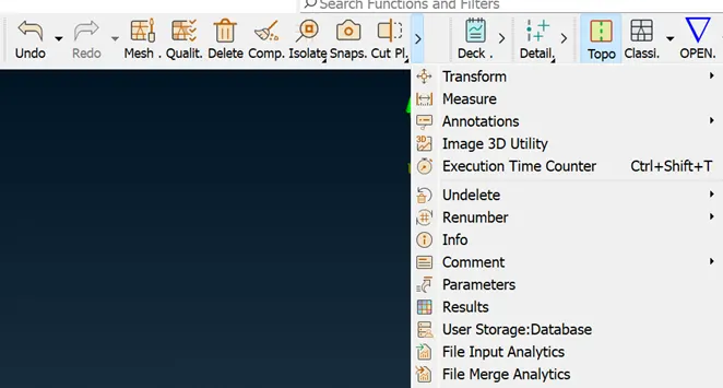
Fig 15. Transform option
- in transform we have options like move or copy we have to choose here copy. After selecting copy there are options of entities or nodes we select entities and select the half body using box selection and hit the mouse middle click.
- After selecting the body we have to select 3 point plane option and then select the 3 points randomly like shown in below image.
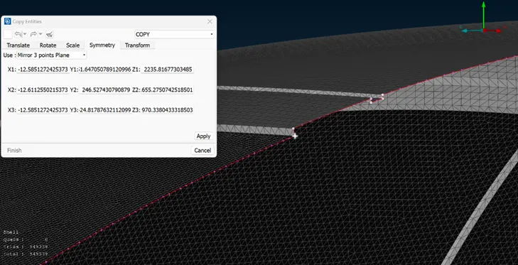
Fig 16. 3 points selecting
- Now after selecting 3 points we do the middle click we will get our another half part now we have to do the topo and check is there any single con present, if any we have to do topo there.
- Now after completing the geometry check the geometry and mesh as if there any part left unmeshed or any elements exceeds the mesh quality criteria.
- After full body cleanup we now move forward to create the wind tunnel around the car body, for wind tunnel dimensions we have some standards according to which we have to build our wind tunnel.
- To build wind tunnel we go to topo mode again where we select the point relative option and first click on centre point of our geometry at bottom surface of car and after selecting when we click the middle click of mouse it ask us to give the dimension at the particular direction like here we select the -y as it is lying on y-axis negative side and in that we define the dimension value which here we gave 75 mm. like wise remaining sides are given below
- For top side dimensions should be 3X+ dist from centre to top of body, where X is length of car which is 1300 so our value becomes 3(1300)+300=4200mm
- For backside of car dimensions are 6X+ dist. from centre to back, which is 6(1300)+610=8410mm
- For front side of car dimensions are 4X + Dist. From centre to front , which is 4(1300)+650=5850mm
- For both sides of car right and left its 1X which is 1300mm
- After creating points nots its time to join those points, so by using curve option we join those points. After joining we create the surface there, like first we create the bottom surface then offset those to top side, and then we join those by using new face option.
- After completing wind tunnel now lets move to surface mesh of tunnel, here we have to only focus on intimate part of tunnel which is near our automotive body because excessive fine mesh is waste of computational power and time. So at bottom surface the mesh length we given is 20mm and at upper surface which is top surface we use the 100mm mesh but now the issue is the mesh should be go on increase from bottom to top which is from 20-100mm so now we use spacing option here, which help our mesh to go stepwise so we select the spacing and then define minimum value to 20 an maximum limit to 100 with factor of 1.1. after creating all those points Now we will mesh the faces
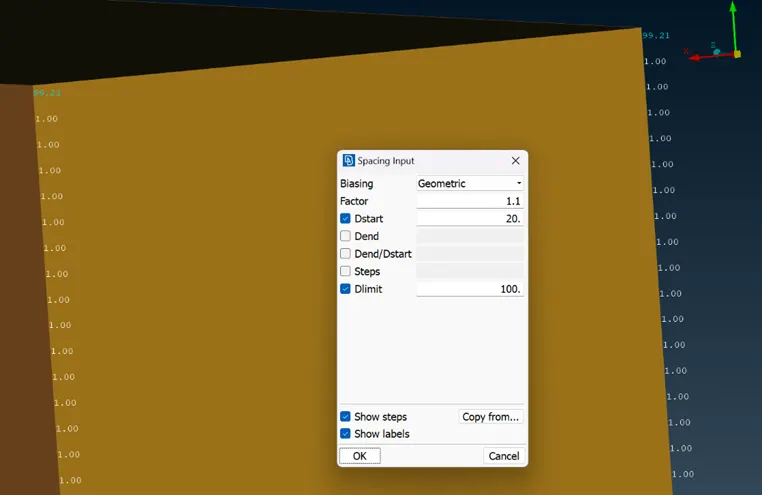
Fig 17. Spacing setting
- After surface mesh we are at the last stage of our project which is creating volumetric mesh, so we go to v.mesh and click on define, after defining we get various surface but we have to kept one common volume so according to that we have to select those and delete rest of all volumes. We didn’t create the volumetric mesh here because it will consume near about 2 days to construct the complete mesh.
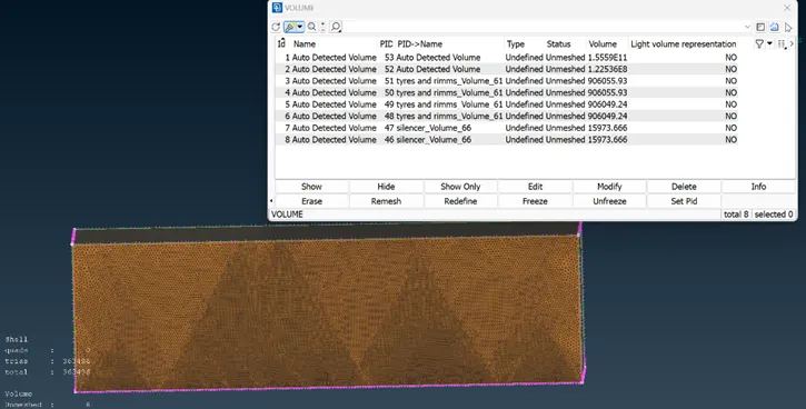
Fig 18. Number of volumes detected
Learning outcomes :
Here from this challenge we get to learn how to clear the complex geometry in very systematic way also we learn how to manage the mesh without disturbing the neighbour geometry mesh.
Also we learn various new tools, and new functions of old tools as well and various option we can use for geometry cleanup and mesh managing.
Result :
As a result we create the mesh and clear geometry which we can now use to do the CFD simulation with zero error in pre-processing which. We remove excessive surfaces, overlapping surfaces, extra cons, unwanted hot-points and create the geometry as one single volume which we can see below.
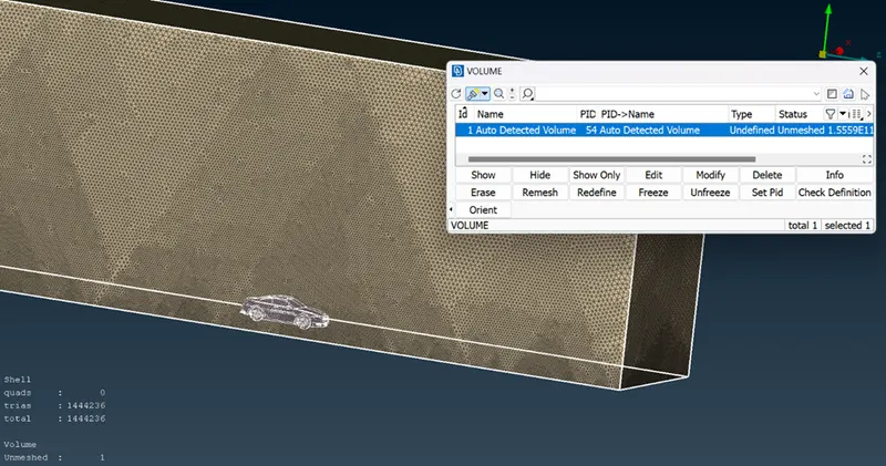
Fig 19. Resulted Geometry
Conclusion :
In the end we conclude that as compare to geometry we got or we imported now we make a geometry more clear and errors free which we can ready to take for CFD simulation once its volumetric mesh is done.