Week 4 Challenge
1). Define Tooling direction
* The tooling direction is the direction in which the mold or core and cavity opens.
* The mold has sides namely Core side and Cavity side.
* The core is the movable part which forms the internal shape of the molding whereas Cavity is the fixed part where the plastic material gets filled.
* The cavity forms the external shape of the molding,
* The core pulls apart from the cavity and that is called as the Tooling direction.
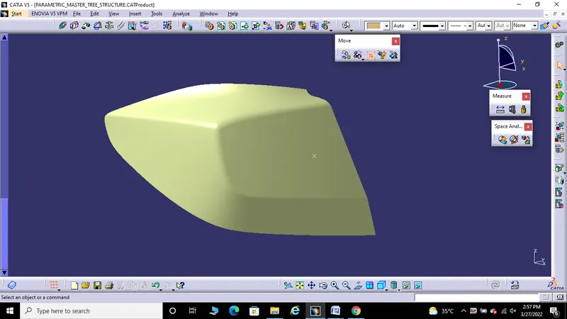
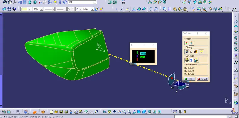
2) Create tooling direction for Class A with 10 deg draft ( draft in command should be 10 deg) and show the draft analysis
* The tooling direction is the direction in which the mold opens and closes.
STEP 1: Create a point on the surface of the part which is suitable for molding process.
STEP 2: Create an Axis system with reference to the point created.
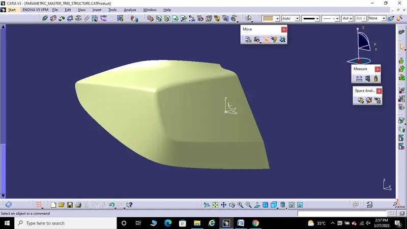
STEP 3: Create a Line in which the line should pass the Y axis of the specified axis system.
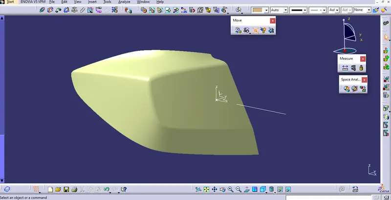
With this line, The Part shows negative draft and so the Line is drawn with an angle of 12 degree
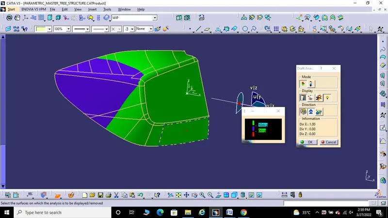
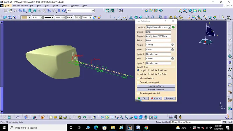
The tooling direction for Class A with 10 deg draft ( draft in command should be 10 deg) and the draft analysis is created and shown.
3) Definition of Parting Line
* Parting line is the area in which the components and the parting surface meets.
* In other words, it is a meeting point between the core and the cavity during injection molding.
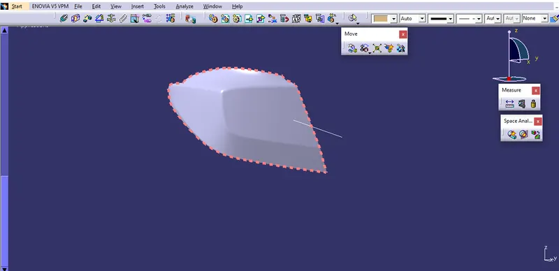
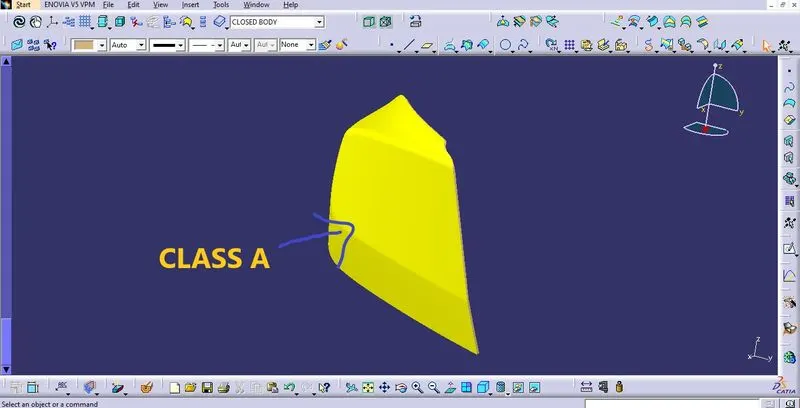
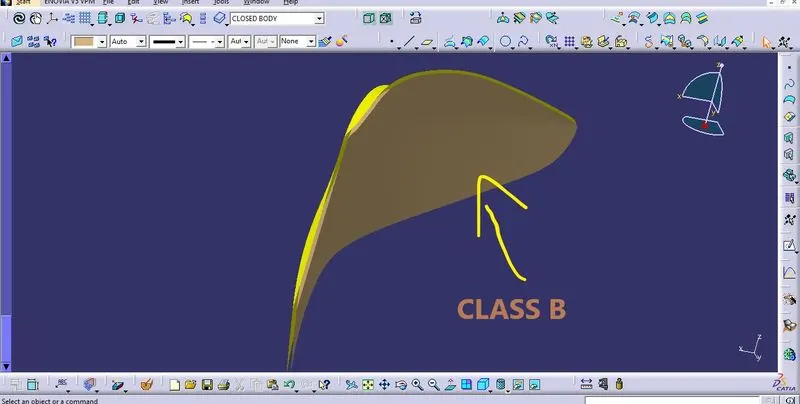
4) Create B surface of the given lens in surface modeling (not in part), with 4 mm thickness
* Intially, Class A surface is checked for its curvature continuity and for the quality of the skin data.
* After verifying it, Offset of Class A surface is made in the B side features direction with a distance of 4mm.
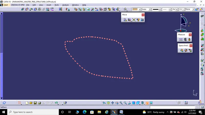
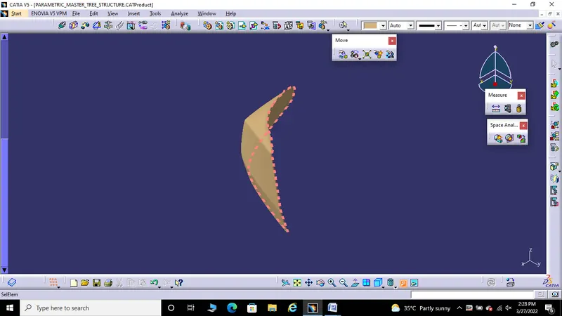
5. Create a parting line for thickened Lens
* Parting line is nothing but the meeting point of the core and cavity of the mold.
* Parting line in the edge of the B surface or the thickened surface as it is the meeting point of the mold.