Week 4 Challenge
Aim:- To design the abutment as per IRC-6, IRC-78.
Explanation:- Abutment is a foundation which is needed to be designed using the various possible load acting on it. For safety conditions, it is to be checked for ULS & SLS. The total span of the bridge is 14.4 m and the width of the carriageway is 12m, in addition to it there is a footpath of 1.50m on one side of the carriageway and a crash barrier of 0.5m on each side.
| Basic design details | ||
| 1 | Basic design data | |
| 1.1 | Span and cross-section data | |
| C/C of expansion gap | 14.4 m | |
| C/C of bearing | 13.4 m | |
| Distance of bearing to expansion gap | 0.5 m | |
| Total Width | 12m | |
| Carriageway width | 9 | |
| Footpath Width (Left side) | 1.5m | |
| Foothpath width (Rigth side) | 0 | |
| Crash Barrier Width (Left side) | 0.5m | |
| Crash Barrier Width (Rightside) | 0.5m | |
| Handrail width (Left side) | 0 | |
| Handrail width (Rightside) | 0 | |
| Skew angle | 0 | |
| Width of median | 0.5m | |
| 2 | Superstructural details | |
| Number of girders | 4 | |
| spacing of girders | 3m | |
| Cantilever on both sides | 1.5m | |
| Depth of superstructures | 1.22m | |
| Wearing coat thickness | 0.065m | |
| Distance of FRL from bearing at least height | 10.9m | |
| Bearing Thickness | 0.035m | |
| Pedestal thickness | 0.25m | |
| Bearing+pedestal thickness | 0.315m | |
| 3 | Levels | |
| Height of Substructures | 6m assume | |
| Scour Level MSL | 226.58 | |
| Min foundation level required | 224.25 | |
| HFL | 229.5 | |
| Clear cover for dirt wall | 50mm | |
| Clear cover for abutment cap | 50mm | |
| Clear cover for abutment stem | 75mm | |
| Clear cover for foundation | 75mm | |
| 4 | Material Used | |
| Grade of concrete fck | M35 | |
| Design of concrete fcd | 15.63 | |
| Grade of steel fyk | Fe500 | |
| The design strength of steel fyd | 434.8 | |
| The density of RC Concrete | 2.5 | |
| The density of wearing a coat | 2.2 | |
| Coef. Of thermal expansion of steel | 1.2 E-05/ºc | |
| Shrinkage strain | 2.00E-04 | |
| Modulus of elasticity of steel Es | 20000000 Mpa | |
| Modulus of elasticity of concrete Ecm for M35 | 32000 Mpa | |
| Mean axial tensile strength of concrete fctm | 2.8 Mpa | |
| 5 | Soil parameters | |
| The angle of shear resistance | 30 | |
| The density of dry backfill | 2 t/m3 | |
| Density of submerged backfill | 1 t/m3 | |
| Net SBC | 25 t/m3 | |
| Gross SBC (LWL) | 33.42 t/m3 | |
| Gross SBC (HFL) | 27 t/m3 | |
| Live load surcharge | 1.2 m | |
| Type of soil | medium soil | |
| Coefficient of friction | 0.5 | |
| 6 | Dimension of the abutment | |
| Length of the abutment at top | 1.64m | |
| Length of the abutment at bottom | 1m | |
| Width of abutment | 12m | |
| Width of the median wall | 3.5m | |
| with of the footing | 6.3m | |
| width of the heel | 3.5m | |
| width of the toe | 1.8m | |
| heel thickness at the root | 1m | |
| toe thickness at the root | 1m | |
| stem thickness | 1m | |
| Dirtwall thickness | 0.3m | |
| depth of the abutment cap varying | 0.3m | |
| depth of abutment cap uniform | 0.3m | |
| return wall thickness | 0.5m |
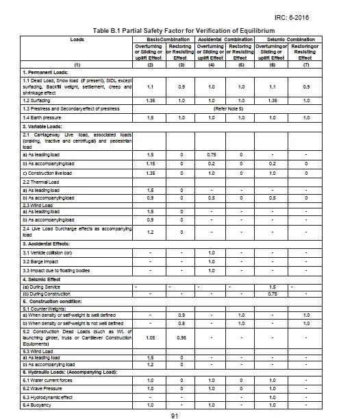
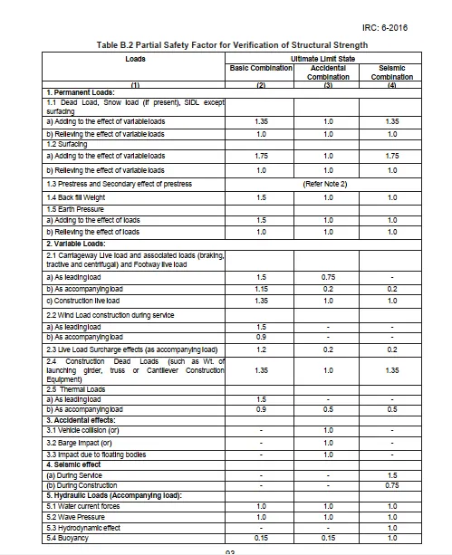
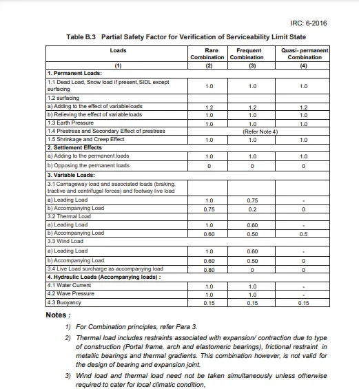
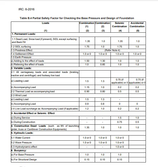
The combination of loads as per limit sate design givenn by IRC-6 in Annexure-B are as follow:-
- Load Calculation:-
For the calculation of the self-weight, the specification will be as per clause 203 of IRC-6.
| 7 | Dead load on superstructure | |
| Dead load | ||
| Total weight of super structure | 199t | |
| DL reaction of one span | 99.5t | |
| Unbalanced longitudianal moment | 0tm | |
| Transverse ecc. Of DL from abutment c/l | 0m | |
| Transverse moment due to unbalanced DL | 0tm | |
| Weight of crash barrier | 1t/m | |
| Weight of crash barrier | 28.8t | |
| Weight of medain | 14.4t | |
| Weight of footh path | 16.2t | |
| Total DDL | 59.4t | |
| SDL reaction on one span | 29.7t | |
| FPLL | 1t | |
| Unbalanced longitudianal moment | 0t/m | |
| Transverse moment due to unbalanced vertival load | 130.95tm | |
| Weight of wearing coat | 0.22t/m2 | |
| Weight of wearing coat | 28.512t | |
| SDL WC raectionof one span | 14.256t | |
| Unbalanced longitudianal moment | 0tm | |
| Tannsverse moment due to unbalanced vertical load | 0tm | |
| 8 | Live load | |
| Load % to be taken after reduction | No reduction | |
| Bearing Type | Elastomeric | |
| 9 | Seismic laod | |
| Seismic zone | III | |
| Importance factor | 1.2 | |
| Response reductiion factor | 1.5 | |
| Temperature variation | 47.5 degree C | |
| conditiion of exposure | Moderate | |
| Factor by which seismic force is increased | 1.35 |
| 10 | Earth Prssure loads | |
| Active and passive EP coeff | ||
| Angle pf shear resistance | 30 | |
| Density of dry backfill | 2t/m3 | |
| density of submerged backfill | 1t/m3 | |
| Net SBC | 25t/m3 | |
| Gross SBC (LWL) | 33.42t/m3 | |
| Gross SBC (HFL) | 27t/m3 | |
| Live load surcharge | 1.2m | |
| Type of soil | medium soil | |
| Coefficient of Friction | 0.5 | |
| Alpha | 90 | |
| Beta | 0 | |
| Delta | 20 | |
| Ka | 0.297 | |
| Kp | 6.15 | |
| Kah | 0.279 | |
| Kav | 0.102 | |
| Kph | 5.738 | |
| Kpv | 2.088 | |
| 11 | Normal case LWL | |
| Force due to Earthpressure | 128.304t | |
| lever arm, 0.42H | 2.52m | |
| Moment, ML | 323.3261tm | |
| 12 | HFL case | |
| E1 | ||
| E2 | 16.2t | |
| E3 | 92.2t | |
| Total | 217.9t | |
| ML | 207.35tm |
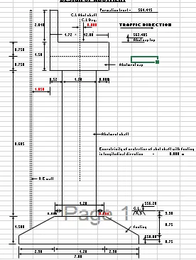
| Weight of super structure | |||||
| Discription | weight | lever arm | ML | Lever arm | ML abt toe |
| t | m | tm | m | tm | |
| Stem | 162 | 0 | 0 | 2.3 | 372.6 |
| Abutment cap | 2664 | 0 | 0 | 2.3 | 64.272 |
| Dirt wall bracket | 4.05 | 0.973 | 3.94 | 2.97 | 12.0285 |
| Dirt wall | 16.85 | 0.67 | 11.29 | 2.97 | 20.0445 |
| Total | 209.54 | 15.23 | 495.945 | ||
| Weight of substructure | 209.54 t | ||||
| Buoyancy on stem | -51 | ||||
| Long. Moment due to buoyancy | -117.3 | ||||
| Weight of foundation | |||||
| Self weight of footing | 53.34 m3 | ||||
| Volume | 133.35t | ||||
| Weight | -53.34t | ||||
| Buoyancy force | 3.15 m | ||||
| ML-foundation | 420.05 tm | ||||
| ML-buoyancy | -168.02tm | ||||
| Return wall | |||||
| Total weight | 59 | ||||
| Moment, ML | 304.6 |
| The bridge shall be design for IRC live loads as per IRC-6.Variou combination for the proposed lane widths will be done to get the worst effect. | |||||||
| Live load | |||||||
| 1 lane of 70R wheeled | |||||||
| Ra | 69.444t | ||||||
| Rb | 28.55t | ||||||
| Bracking Force | 19.6t | ||||||
| Change inn reaction due to bracking force | 4t | ||||||
| Vertical force on abutment, max | 73.44t | ||||||
| Vertical force on abutment, min | 65.444t | ||||||
| Longitudinal moment | 0tm | ||||||
| Horizontal force= Fh/2 | 9.8t | ||||||
| HL | 9.8t | ||||||
| Transverse eccentricity for 1 lane 70R wheel | 1.905m | ||||||
| Transverse moment | 139.9032tm | ||||||
| 2L CL-A | |||||||
| Live load reactions | |||||||
| Ra | 57.4t | ||||||
| Rb | 27.4t | ||||||
| Bracking Force | 22.16t | ||||||
| Change inn reaction due to bracking force | 2t | ||||||
| Vertical force on abutment, max | 59.4t | ||||||
| Vertical force on abutment, min | 55.4t | ||||||
| Longitudinal moment | 0tm | ||||||
| Horizontal force= Fh/2 | 11.08t | ||||||
| HL | 1.85m | ||||||
| Transverse eccentricity for 2 lane class-A | 109.89tm | ||||||
| Transverse moment | |||||||
| Summary | |||||||
| Live load case | Max.load | Min.load | ML | MT | HL | HT | |
| 1lane of 70R wheeled | 73.44 | 65.44 | 0 | 139.9 | 9.8 | 0 | |
| 2L CL-A | 59.4 | 59.4 | 0 | 109.89 | 11.08 | 0 | |
| Summary | |||||||
| Force at bearing level | |||||||
| Load case | Load P | Load (min) | ML | MT | HL | HT | |
| t | tm | tm | t | t | |||
| DL | 99.5 | 0 | 0 | 0 | 0 | ||
| SIDL | 29.7 | 0 | 130.95 | 0 | 0 | ||
| SIDL(WC) | 14.26 | 0 | 0 | 0 | 0 | ||
| LL | 73.44 | 65.44 | 82.06 | 139.9 | 9.8 | 0 | |
| Force at abutment bottom level | |||||||
| Load case | Load P | Load (min) | ML | MT | HL | HT | |
| t | tm | tm | t | t | |||
| DL | 99.5 | 0 | 0 | 0 | 0 | ||
| SIDL | 29.7 | 0 | 130.95 | 0 | 0 | ||
| SIDL(WC) | 14.26 | 0 | 0 | 0 | 0 | ||
| LL | 73.44 | 65.44 | 82.06 | 139.9 | 9.8 | 0 | |
| Force at abutment bottom level | |||||||
| Ecc.From footing center to toe 2.30 | |||||||
| Load case | Load P | Load (min) | ML due to P (abt toe) | MT | HL | HT | ML due to HL |
| t | tm | tm | t | t | tm | ||
| DL | 99.5 | 228.85 | 0 | 0 | 0 | 0 | |
| SIDL | 29.7 | 68.31 | 130.95 | 0 | 0 | 0 | |
| SIDL(WC) | 14.26 | 32.79 | 0 | 0 | 0 | 0 | |
| LL | 73.44 | 65.44 | 168.91 | 139.9 | 9.8 | 0 | -91.86 |
| Check for overturning and stabality | |||||||||
| Overturning stabality check | |||||||||
| Loads | Unfactored ML (tm) | Factors | Resisting ML (tm) | Overturning ML (tm) | |||||
| DL | 228.85 | R | 0.95 | 217.41 | 0 | ||||
| SDL | 68.31 | R | 0.95 | 64.89 | 0 | ||||
| Wearing coat | 32.79 | R | 1 | 32.79 | 0 | ||||
| Weight of substructure | 495.59 | R | 0.95 | 471.15 | 0 | ||||
| Weight of footing | 420.05 | R | 0.95 | 399.05 | 0 | ||||
| Weight of soil above footing | 3604.1 | R | 0.95 | 3423.9 | 0 | ||||
| LL | 139.9 | R | 0 | 0 | 0 | ||||
| Earth pressure | 323.33 | O | 1.5 | 0 | -484.99 | ||||
| Earth pressure | 207.35 | R | 0 | 0 | 0 | ||||
| LLS | -453.5 | O | 1.2 | -544.2 | -544.2 | ||||
| LL | 109.89 | O | 1.5 | 164.84 | 0 | ||||
| Mr | Mo | ||||||||
| Total | 4229.82 | -1029.19 | |||||||
| FO | Mr/Mo | 4.11 | Safe | ||||||
| Sliding stabality check | |||||||||
| Loads | Unfactored ML (tm) | Factors | Factored HL (t) | P min (t) | Factor | Factored Pmin | |||
| DL | 0 | R | 0.95 | 0 | 99.5 | R | 0.95 | 94.53 | |
| SDL | 0 | R | 0.95 | 0 | 29.7 | R | 0.955 | 28.22 | |
| Wearing coat | 0 | R | 1 | 0 | 14.26 | R | 1 | 14.26 | |
| Weight of substructure | 0 | R | 0.95 | 0 | 209.54 | R | 0.95 | 199.06 | |
| Weight of footing | 0 | R | 0.95 | 0 | 133.35 | R | 0.95 | 126.688 | |
| Weight of soil above footing | 0 | R | 0.95 | 0 | 1086.1 | R | 0.95 | 1031.8 | |
| LL | 9.8 | S | 1.5 | 14.7 | 65.44 | R | 0 | 0 | |
| Earth pressure | 217.9 | S | 1.5 | 326.85 | 128.3 | R | 0 | 0 | |
| LLS | 85.4 | S | 1.2 | 102.48 | 0 | R | 1.2 | 0 | |
| Total | 444.03 | U | 1494.54 | ||||||
|
0.5 | ||||||||
| FOS | μ∑P/∑H | 1.68 | Safe | ||||||
| Loads for base pressure | |||||||||||
| loads | Pmax | Pmin | ML | ML due to P | MT | ||||||
| DL | 99.5 | 99.5 | 0 | 228.85 | 2 | ||||||
| SDL | 29.7 | 29.7 | 0 | 68.31 | 0 | ||||||
| Wearing coat | 14.26 | 14.26 | 0 | 32.79 | 0 | ||||||
| LL | 73.44 | 65.44 | -91.86 | 168.91 | 139.9 | ||||||
| Erath pressure | 128.3 | 128.3 | -323.33 | 207.35 | 0 | ||||||
| LLS | 0 | 0 | 0 | 0 | 0 | ||||||
| Weight of sub structure | 209.54 | 209.54 | 0 | 495.945 | 0 | ||||||
| Weight of footing | 133.35 | 133.35 | 0 | 420.05 | 0 | ||||||
| Weight of soil above footing | 1086 | 1086 | -1033 | 3604 | 0 | ||||||
| Total | 1774.09 | 1766.09 | -1448.18 | 5226.21 | 139.9 | ||||||
| Eccentricity | 0.85m | ||||||||||
| Longitudinal Moment | 658.57 tm | ||||||||||
| Pmax | Pmin | ML | MT | ||||||||
| Load combination1 | 1774.09 | 1766.09 | 658.57 | 139.9032 | |||||||
| Combination for base pressure | |||||||||||
| P1=(P/A)+[(ML/ZL)]+[(MT/ZT)] | 32.68851< Gross SBC, OK | ||||||||||
| P2=(P/A)+[(ML/ZL)]-[(MT/ZT)] | 30.83794< Gross SBC, OK | ||||||||||
| P3=(P/A)-[(ML/ZL)]-[(MT/ZT)] | 14.24509< Gross SBC, OK | ||||||||||
| P4=(P/A)-[(ML/ZL)]+[(MT/ZT)] | 16.09566< Gross SBC, OK | ||||||||||
| Combination for Base pressure and designof foundation | |||||||||||
| For Pmax | |||||||||||
| Pmax | Pmin | ML | MT | P1 | P2 | P3 | P4 | ||||
| ULS Condition | 2430.99 | 2418.99 | 1507.9 | 209.85 | 52.54 | 49.76 | 11.77 | 14.55 | |||
| Service condition | 1774.09 | 1766.09 | 658.57 | 139.9 | 32.69 | 30.84 | 14.25 | 16.1 | |||
| For Pmin | |||||||||||
| P1 | P2 | P3 | P4 | ||||||||
| 52.38 | 49.61 | 11.61 | 14.39 | ||||||||
| 32.58 | 30.73 | 14.14 | 15.99 | ||||||||
| Factored load for design | |||||||||||
| Loads | Factors | Pmax | Pmin | ML | ML due to P | MT | Factored Pmax | Factored Pmin | Factored Ml | Factored ML due to P | Factored MT |
| DL | 1.35 | 99.5 | 99.5 | 0 | 228.85 | 0 | 134.33 | 134.33 | 0 | 308.95 | 0 |
| SDL | 1.35 | 29.7 | 29.7 | 0 | 68.31 | 0 | 40.1 | 40.1 | 0 | 92.22 | 0 |
| Wearing coat | 1.75 | 14.26 | 14.25 | 0 | 32.79 | 0 | 24.95 | 24.95 | 0 | 57.38 | 0 |
| LL | 1.5 | 73.44 | 65.44 | -91.86 | 168.91 | 139.9 | 110.46 | 98.16 | -137.78 | 253.37 | 209.85 |
| Earth pressure | 1.5 | 128.3 | 128.3 | 323.33 | 207.35 | 0 | 192.46 | 192.46 | 484.99 | 311.03 | 0 |
| LLS | 1.2 | 0 | 0 | 0 | 0 | 0 | 0 | 0 | 0 | 0 | 0 |
| Weight of sub structure | 1.35 | 209.54 | 209.54 | 0 | 495.945 | 0 | 282.88 | 282.88 | 0 | 669.53 | 0 |
| Weight of footing | 1.35 | 133.35 | 133.35 | 0 | 420 | 0 | 180.02 | 180.02 | 0 | 567.07 | 0 |
| Weight of soil abovee footing | 1.35 | 1086 | 1086 | 1033 | 3604 | 0 | 1466.1 | 1466.1 | 1394.55 | 4865.4 | 0 |
| Total | 2431.3 | 2419 | 1741.76 | 7124.95 | 209.85 | ||||||
| Eccentricity | 0.85m | ||||||||||
| ML | 1507.9tm | ||||||||||
| Pmax | Pmin | ML | MT | ||||||||
| 2431.3 | 2419 | 1507.9 | 209.85 | ||||||||
| Ultimate Limit State | ||||
| Grade of concrete | fck | M35 | ||
| Design strength of concrete | fcd | 15.63 | ||
| Grade of steel | fy | Fe500 | ||
| Design Strength of steel | fyd | 434.8 | ||
| Modulus of elasticity of steel | Es | 200000 | Mpa | |
| Modulus of elasticity of concrete | Ecm | 32000 | Mpa | |
| Cu= | 0.416xu | |||
| xu,lim/d | 0.617 | |||
| Rlim=Mu,lim/bd2 | 0.8095fcd*(xu/d)*(1-0.416*xu/d) | |||
| 5.8 | ||||
| Calculation of reinforcement | ||||
| Design of heel slab | ||||
| Overall depth of the section | 1000mm | |||
| Bmdue to soil pressure | 116.29tm | |||
| BM due to self-weight | -46.82 | |||
| BM due to weight of soil above | -103 | |||
| Net BM= | -33.53 | |||
| Design Moment per m width | -33.53 | |||
| Effective depth required= | sqrt(Mu/R*b) | |||
| Effective depth required= | 240.36mm | |||
| Effective depth available,d= | 912.5mm | |||
| Area of steel required | 1447.35mm2 | |||
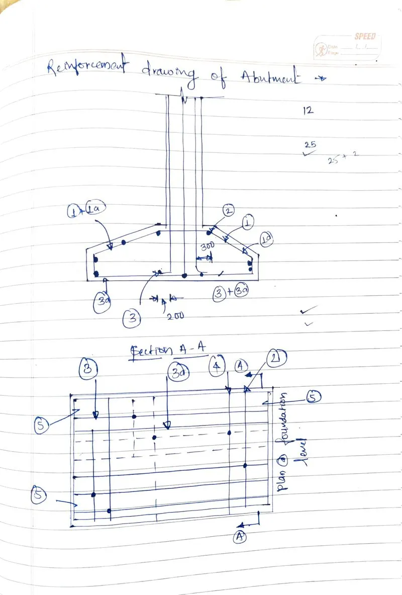
| Dia of main reinforcement | 25mm | |||
| Provide | 25 dia bars @ 200 mm c/c | |||
| Area of steel | 4908.7mm2 | ok | ||
| Checked for minimum and maximum reinforcement as per IRC112 | ||||
3. Shallow foundation in flyover and river bridge.
In River bridges, the shallow foundation is preferred when the bearing capacity of the soil is good. The height of the abutment is short in river bridges. The scouring effect is most predominant and is effectively considered in river bridges. The depth of the foundation is considered on the scouring depth at that site.
In a flyover bridge, a shallow foundation is used when the topsoil has a good bearing capacity. The foundation should be embedded to a depth of 2m below ground level.